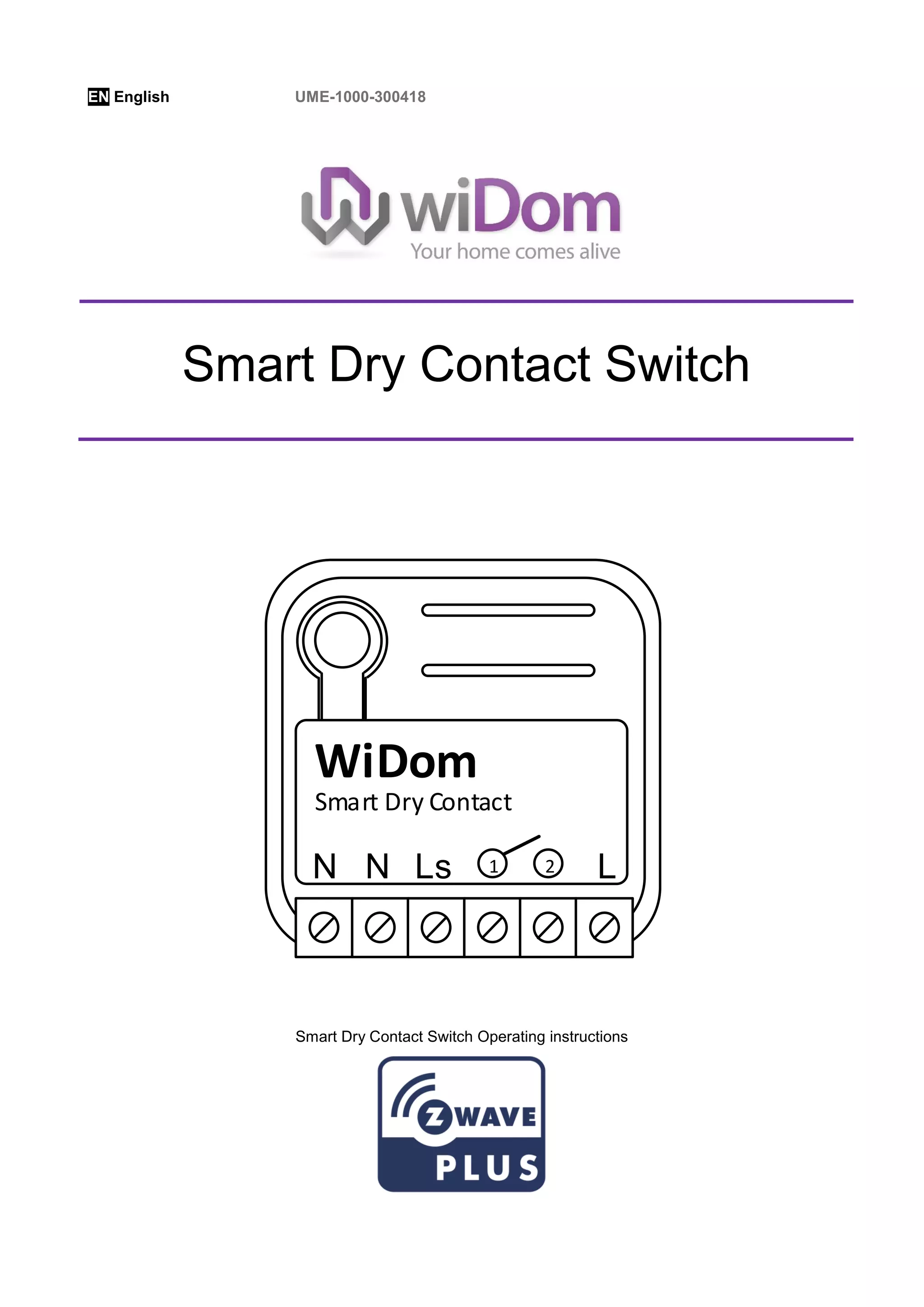
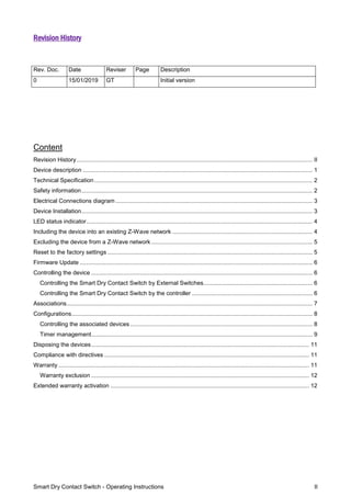
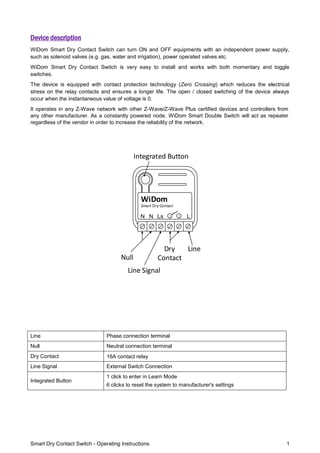
The document provides instructions for operating a Smart Dry Contact Switch, including:
1) The switch can turn on and off equipment with independent power supply, such as valves or motors, and operates in Z-Wave networks.
2) Instructions are given for installation, inclusion in a Z-Wave network, controlling the switch via external buttons or a controller, associations with other devices, and configuration parameters.
3) The switch has a relay, LED status indicator, and can be reset or have its firmware updated.
Manual del dispositivo regulador oculto Z-Wave de Widom que permite variar la intensidad de una lámpara, o la velocidad de un motor (como por ejemplo un ventilador).
Manual of Flow Stop is a motor operated shut-off controller for automatic flow stop of gas and water pipes. It is equipped with Z-Wave Plus technology. This means it is particularly suitable for use in smart homes. By manufacturer PoPP
The micromodule Zipato energy meter monitors the power consumption of two different circuits and signals to any compatible Z-Wave controller in real time.
The smoke detector Z-Wave detects fire and smoke emissions. In case of emergency, it gives an audible alert and sends an alarm signal to the Z-Wave network
The 6 in 1 multisensor from Aeon Labs is a Z-WAve Plus multifunction peripheral which is both a temperature sensor, humidity, movement, UV light and vibration.
WiDomSmartTE Dimmer is an "in-wall device" that controls the luminosity level and/or fan speed. A universal device that controls the light intensity of all types of dimmable lights, including LED lamps and energy-saving lamps. The Smart TE Dimmer includes the ON / OFF control option of non-dimmable loads
With the WiDom flush-mounted Double Switch Relay, you can integrate existing electrical installations (e.g. lighting, airing systems…) into a Z-Wave network.
Mini Zipato drive with energy measurement allows the variation in your interior lighting to create a pleasant atmosphere in your home and also help you to reduce your energy consumption. Actually it is able to transmit the instantaneous power consumption (W) and cumulative (KWh) of equipment attached to it.
The WiDom Roller Shutter V2 is a small and compact device which can control your roller shutters, blinds, curtains, etc. Thanks to its sophisticated design the modul fits into a junction box
The G5 Instruments are high performance single-channel weight indicators (PM model, panel mounted) or weight transmitters (RM model, DIN rail mounted) intended for industrial systems.
The basic function is to convert the signals from strain gauge transducers to useful weight information. Transducer excitation is included as well as parameter controlled signal processing, indication of output levels, error supervision and operation of optional external equipment.
As long as the error supervision detects no error, a signal called ‘In process’ is then present but if an error is detected, ‘In process’ will be off and a specific error message will be displayed. ‘In process’ can be set to control any digital output. Note that there are weighing channel specific and instrument specific error detection.
All functions in the G5 Instrument are controlled by set-up parameters. Setting of parameter values can be done from the PM front panel. Set-up of a RM model must be done with a web browser in a PC that is connected to the instrument via Ethernet. Maintenance functions can be accessed locally (PM) or remotely (PM and RM).
Optimal protection for critical loads. To limit starting currents on problematic devices, such as energy saving bulbs and fluorescent bulbs. Problematic devices, such as electronic ballasts, energy-saving light bulbs, incandescent bulbs, LED drivers, and switching power supplies, consume a lot of power during ignition due to the multiplication of current. nominal and can therefore destroy the switching relay.
With the ESB200 current limiter, the high current that can occur when switching on electronic devices is limited to a harmless value. It is also possible to limit the inrush current of incandescent lamps to give them a longer life. A protection fuse is also integrated. This starting current limiter can be plugged directly into the power supply circuit for loads up to 200 VA. This compact device can be installed very easily in junction and recessed boxes or in lamp boxes, for example. The device is easily installed in series with the load
wiDom Multi Sensor Room Controller MSRC Manual ENDomotica daVinci
WiDom Multi Sensor Room Controller is a Z-Plus Static controller that integrates a Luminance, Humidity, Temperature and Loudness sensor in the same box
GraphSummit Singapore | The Future of Agility: Supercharging Digital Transfor...Neo4j
Leonard Jayamohan, Partner & Generative AI Lead, Deloitte
This keynote will reveal how Deloitte leverages Neo4j’s graph power for groundbreaking digital twin solutions, achieving a staggering 100x performance boost. Discover the essential role knowledge graphs play in successful generative AI implementations. Plus, get an exclusive look at an innovative Neo4j + Generative AI solution Deloitte is developing in-house.
LF Energy Webinar: Electrical Grid Modelling and Simulation Through PowSyBl -...DanBrown980551
Do you want to learn how to model and simulate an electrical network from scratch in under an hour?
Then welcome to this PowSyBl workshop, hosted by Rte, the French Transmission System Operator (TSO)!
During the webinar, you will discover the PowSyBl ecosystem as well as handle and study an electrical network through an interactive Python notebook.
PowSyBl is an open source project hosted by LF Energy, which offers a comprehensive set of features for electrical grid modelling and simulation. Among other advanced features, PowSyBl provides:
- A fully editable and extendable library for grid component modelling;
- Visualization tools to display your network;
- Grid simulation tools, such as power flows, security analyses (with or without remedial actions) and sensitivity analyses;
The framework is mostly written in Java, with a Python binding so that Python developers can access PowSyBl functionalities as well.
What you will learn during the webinar:
- For beginners: discover PowSyBl's functionalities through a quick general presentation and the notebook, without needing any expert coding skills;
- For advanced developers: master the skills to efficiently apply PowSyBl functionalities to your real-world scenarios.
State of ICS and IoT Cyber Threat Landscape Report 2024 previewPrayukth K V
The IoT and OT threat landscape report has been prepared by the Threat Research Team at Sectrio using data from Sectrio, cyber threat intelligence farming facilities spread across over 85 cities around the world. In addition, Sectrio also runs AI-based advanced threat and payload engagement facilities that serve as sinks to attract and engage sophisticated threat actors, and newer malware including new variants and latent threats that are at an earlier stage of development.
The latest edition of the OT/ICS and IoT security Threat Landscape Report 2024 also covers:
State of global ICS asset and network exposure
Sectoral targets and attacks as well as the cost of ransom
Global APT activity, AI usage, actor and tactic profiles, and implications
Rise in volumes of AI-powered cyberattacks
Major cyber events in 2024
Malware and malicious payload trends
Cyberattack types and targets
Vulnerability exploit attempts on CVEs
Attacks on counties – USA
Expansion of bot farms – how, where, and why
In-depth analysis of the cyber threat landscape across North America, South America, Europe, APAC, and the Middle East
Why are attacks on smart factories rising?
Cyber risk predictions
Axis of attacks – Europe
Systemic attacks in the Middle East
Download the full report from here:
https://sectrio.com/resources/ot-threat-landscape-reports/sectrio-releases-ot-ics-and-iot-security-threat-landscape-report-2024/
PHP Frameworks: I want to break free (IPC Berlin 2024)Ralf Eggert
In this presentation, we examine the challenges and limitations of relying too heavily on PHP frameworks in web development. We discuss the history of PHP and its frameworks to understand how this dependence has evolved. The focus will be on providing concrete tips and strategies to reduce reliance on these frameworks, based on real-world examples and practical considerations. The goal is to equip developers with the skills and knowledge to create more flexible and future-proof web applications. We'll explore the importance of maintaining autonomy in a rapidly changing tech landscape and how to make informed decisions in PHP development.
This talk is aimed at encouraging a more independent approach to using PHP frameworks, moving towards a more flexible and future-proof approach to PHP development.
Climate Impact of Software Testing at Nordic Testing DaysKari Kakkonen
My slides at Nordic Testing Days 6.6.2024
Climate impact / sustainability of software testing discussed on the talk. ICT and testing must carry their part of global responsibility to help with the climat warming. We can minimize the carbon footprint but we can also have a carbon handprint, a positive impact on the climate. Quality characteristics can be added with sustainability, and then measured continuously. Test environments can be used less, and in smaller scale and on demand. Test techniques can be used in optimizing or minimizing number of tests. Test automation can be used to speed up testing.
GraphRAG is All You need? LLM & Knowledge GraphGuy Korland
Guy Korland, CEO and Co-founder of FalkorDB, will review two articles on the integration of language models with knowledge graphs.
1. Unifying Large Language Models and Knowledge Graphs: A Roadmap.
https://arxiv.org/abs/2306.08302
2. Microsoft Research's GraphRAG paper and a review paper on various uses of knowledge graphs:
https://www.microsoft.com/en-us/research/blog/graphrag-unlocking-llm-discovery-on-narrative-private-data/
Removing Uninteresting Bytes in Software FuzzingAftab Hussain
Imagine a world where software fuzzing, the process of mutating bytes in test seeds to uncover hidden and erroneous program behaviors, becomes faster and more effective. A lot depends on the initial seeds, which can significantly dictate the trajectory of a fuzzing campaign, particularly in terms of how long it takes to uncover interesting behaviour in your code. We introduce DIAR, a technique designed to speedup fuzzing campaigns by pinpointing and eliminating those uninteresting bytes in the seeds. Picture this: instead of wasting valuable resources on meaningless mutations in large, bloated seeds, DIAR removes the unnecessary bytes, streamlining the entire process.
In this work, we equipped AFL, a popular fuzzer, with DIAR and examined two critical Linux libraries -- Libxml's xmllint, a tool for parsing xml documents, and Binutil's readelf, an essential debugging and security analysis command-line tool used to display detailed information about ELF (Executable and Linkable Format). Our preliminary results show that AFL+DIAR does not only discover new paths more quickly but also achieves higher coverage overall. This work thus showcases how starting with lean and optimized seeds can lead to faster, more comprehensive fuzzing campaigns -- and DIAR helps you find such seeds.
- These are slides of the talk given at IEEE International Conference on Software Testing Verification and Validation Workshop, ICSTW 2022.
DevOps and Testing slides at DASA ConnectKari Kakkonen
My and Rik Marselis slides at 30.5.2024 DASA Connect conference. We discuss about what is testing, then what is agile testing and finally what is Testing in DevOps. Finally we had lovely workshop with the participants trying to find out different ways to think about quality and testing in different parts of the DevOps infinity loop.
Threats to mobile devices are more prevalent and increasing in scope and complexity. Users of mobile devices desire to take full advantage of the features
available on those devices, but many of the features provide convenience and capability but sacrifice security. This best practices guide outlines steps the users can take to better protect personal devices and information.
A tale of scale & speed: How the US Navy is enabling software delivery from l...sonjaschweigert1
Rapid and secure feature delivery is a goal across every application team and every branch of the DoD. The Navy’s DevSecOps platform, Party Barge, has achieved:
- Reduction in onboarding time from 5 weeks to 1 day
- Improved developer experience and productivity through actionable findings and reduction of false positives
- Maintenance of superior security standards and inherent policy enforcement with Authorization to Operate (ATO)
Development teams can ship efficiently and ensure applications are cyber ready for Navy Authorizing Officials (AOs). In this webinar, Sigma Defense and Anchore will give attendees a look behind the scenes and demo secure pipeline automation and security artifacts that speed up application ATO and time to production.
We will cover:
- How to remove silos in DevSecOps
- How to build efficient development pipeline roles and component templates
- How to deliver security artifacts that matter for ATO’s (SBOMs, vulnerability reports, and policy evidence)
- How to streamline operations with automated policy checks on container images
In his public lecture, Christian Timmerer provides insights into the fascinating history of video streaming, starting from its humble beginnings before YouTube to the groundbreaking technologies that now dominate platforms like Netflix and ORF ON. Timmerer also presents provocative contributions of his own that have significantly influenced the industry. He concludes by looking at future challenges and invites the audience to join in a discussion.
Communications Mining Series - Zero to Hero - Session 1DianaGray10
This session provides introduction to UiPath Communication Mining, importance and platform overview. You will acquire a good understand of the phases in Communication Mining as we go over the platform with you. Topics covered:
• Communication Mining Overview
• Why is it important?
• How can it help today’s business and the benefits
• Phases in Communication Mining
• Demo on Platform overview
• Q/A
Transcript: Selling digital books in 2024: Insights from industry leaders - T...BookNet Canada
The publishing industry has been selling digital audiobooks and ebooks for over a decade and has found its groove. What’s changed? What has stayed the same? Where do we go from here? Join a group of leading sales peers from across the industry for a conversation about the lessons learned since the popularization of digital books, best practices, digital book supply chain management, and more.
Link to video recording: https://bnctechforum.ca/sessions/selling-digital-books-in-2024-insights-from-industry-leaders/
Presented by BookNet Canada on May 28, 2024, with support from the Department of Canadian Heritage.
2. Smart Dry Contact Switch - Operating Instructions II
Revision History
Content
Revision History................................................................................................................................................. II
Device description ............................................................................................................................................. 1
Technical Specification...................................................................................................................................... 2
Safety information.............................................................................................................................................. 2
Electrical Connections diagram ......................................................................................................................... 3
Device Installation.............................................................................................................................................. 3
LED status indicator........................................................................................................................................... 4
Including the device into an existing Z-Wave network ...................................................................................... 4
Excluding the device from a Z-Wave network ................................................................................................... 5
Reset to the factory settings .............................................................................................................................. 5
Firmware Update ............................................................................................................................................... 6
Controlling the device ........................................................................................................................................ 6
Controlling the Smart Dry Contact Switch by External Switches................................................................... 6
Controlling the Smart Dry Contact Switch by the controller .......................................................................... 6
Associations....................................................................................................................................................... 7
Configurations.................................................................................................................................................... 8
Controlling the associated devices ................................................................................................................ 8
Timer management........................................................................................................................................ 9
Disposing the devices...................................................................................................................................... 11
Compliance with directives .............................................................................................................................. 11
Warranty .......................................................................................................................................................... 11
Warranty exclusion ...................................................................................................................................... 12
Extended warranty activation .......................................................................................................................... 12
Rev. Doc. Date Reviser Page Description
0 15/01/2019 GT Initial version
3. Smart Dry Contact Switch - Operating Instructions 1
Device description
WiDom Smart Dry Contact Switch can turn ON and OFF equipments with an independent power supply,
such as solenoid valves (e.g. gas, water and irrigation), power operated valves etc.
WiDom Smart Dry Contact Switch is very easy to install and works with both momentary and toggle
switches.
The device is equipped with contact protection technology (Zero Crossing) which reduces the electrical
stress on the relay contacts and ensures a longer life. The open / closed switching of the device always
occur when the instantaneous value of voltage is 0.
It operates in any Z-Wave network with other Z-Wave/Z-Wave Plus certified devices and controllers from
any other manufacturer. As a constantly powered node, WiDom Smart Double Switch will act as repeater
regardless of the vendor in order to increase the reliability of the network.
LN
Smart Dry Contact
WiDom
Ls 1 2N
Line
Line Signal
Dry
ContactNull
Integrated Button
Line Phase connection terminal
Null Neutral connection terminal
Dry Contact 16A contact relay
Line Signal External Switch Connection
Integrated Button
1 click to enter in Learn Mode
6 clicks to reset the system to manufacturer's settings
4. Smart Dry Contact Switch - Operating Instructions 2
Technical Specification
Power supply 110 - 230 VAC±10% 50/60 Hz
Maximum Load on Relay 13A resistive Load
System temperature limitation 105°C
Work temperature From -10° to 40° C
Power consumption
< 260 mW in standby
< 480 mW with working load
Radio frequency Check the radio frequency section
Protection system S0 and S2 Security
Maximum distance
Up to 100 m outdoor
Up to 40 m indoor
Dimensions 37x37x17 mm
Actuator element 16 Amp relay
Compliance CE, RoHs
Electrical IP Rating IP20
Radio Frequency
Product Code Z-Wave Frequency Product Code Z-Wave Frequency
DRYEU 868.4MHz, DRYAU 919.8MHz,
DRYBR 919.8MHz, 921.4MHz DRYCN 868.4MHz
DRYCL 919.8MHz, 921.4MHz DRYHK 919.8MHz
DRYCO 908.4MHz, 916MHz DRYIL 916MHz
DRYIN 865.2MHz DRYMY 919.8MHz, 921.4MHz
DRYJP 922.5MHz, 923.9MHz, 926.3MHz DRYSG 920.9MHz, 921.7MHz, 923.1MHz
DRYRU 869.0MHz DRYKR 920.9MHz, 921.7MHz, 923.1MHz
DRYZA 868.4MHz, 869.85MHz DRYTH 920.9 MHz, 921.7MHz, 923.1 MHz
DRYTW 922.5MHz, 923.9MHz, 926.3MHz DRYUS 908.4MHz
DRYAE 868.4MHz, 869.85MHz
Safety information
INFO: WiDom Smart Dry Contact Switch is designed to be installed in flush mounting junction boxes or
close to the load to be controlled.
WARNING: WiDom Smart Dry Contact Switch must be installed by electricians qualified to intervene
on electrical systems in compliance with safety requirements set out by the regulations in force.
DANGER: WiDom Smart Dry Contact Switch must be connected with a voltage of 230 VAC, before
carrying out any operation, please make sure the power main switch is in OFF position.
DANGER: Any procedure requiring the use of the Integrated Button is related only to the installation
phase and is to be considered a service procedure that must be performed by qualified personnel.
This operation must be performed with all necessary precautions for operating in areas with a single level of
insulation.
WARNING: Do not connect loads that exceed the maximum load permitted by the actuator element.
WARNING: All connections must be performed according to the electrical diagrams provided
WARNING: WiDom Smart Dry Contact Switch must be installed in norm-compliant systems suitably
protected from overloads and short circuits.
5. Smart Dry Contact Switch - Operating Instructions 3
Electrical Connections diagram
The device must be supplied by phase and neutral.
Connections must be done following one of the diagrams below: if you need to control a Load connected on
a different power supply system you must follow the diagram on the right side.
Diagram for controlling a Load in the same power supply system
Diagram for controlling a Load connected to an independent
power supply system
LN
Smart Dry Contact
WiDom
Ls 1 2N
L
N
LN
Smart Dry Contact
WiDom
Ls 1 2N
L
N
N) Neutral; L) Phase; Ls) External Switch; 1, 2) Dry contact
WARNING: The power line must be opportunely protected from short-circuits and excess load due to a
failure of the load.
Device Installation
1) Make sure the main switch is set to the OFF position
2) Connect the device based on the diagrams provided
3) Turn the main switch to the ON position
4) Include the device in the Z-Wave network
TIP: The antenna must not be shortened, removed or modified. To ensure
maximum efficiency, it must be installed as shown. Large size metal equipment
near the antenna can negatively affect reception. Each WiDom device is a node in a
mesh network. If there are metal obstacles, the obstacle can often be overcome with
a further triangulation node.
LN
Smart Dry Contact
WiDom
Ls 1 2N
6. Smart Dry Contact Switch - Operating Instructions 4
LED status indicator
The system includes an RGB LED that shows the device’s status during installation:
Solid RED: the device is not included in any network
OFF: the device is already associated to a Z-Wave network
Blink GREEN: the device has sent an unsolicited Multilevel Frame to Lifeline group
Blink YELLOW: the device has sent an unsolicited Meter Frame to Lifeline group
Blink VIOLET: the device has sent a command to the association device. The number of blinks is equal to
the ID Association group
Sequence of GREEN-BLUE Learn Mode for inclusion
Sequence of RED-BLUE Learn Mode for exclusion
INFO: The Learn Mode status is activated or deactivated by a single click on the integrated button.
TIP: To test if the electrical connections are correct, before the inclusion of the device, while pressing n
times the external switch, the RGB LED should flash green for the same amount of times. If it does
not, check the wire connections.
Including the device into an existing Z-Wave network
WiDom Smart Dry Contact Switch is compatible with all Z-Wave/Z-Wave Plus certified controllers. The
device supports both the Network Wide Inclusion mechanism (which offers the ability to be included in a
network, even if the device is not directly connected to the controller) and Normal Inclusion.
By default, the inclusion procedure starts in Normal Inclusion mode and after a short time out the procedure
continues in Network Wide Inclusion mode that lasts for about 20 Seconds.
If you are using the WiDom Multi Sensor Room Controller you can include the device in the preferred room
by clicking on the button and opening the inclusion interface.
Before including the device the LED status indicator is solid RED. The procedure of inclusion is activated by
clicking Add in the inclusion interface and by pressing any sequence of click on the integrated button. As
soon as the inclusion procedure initiates the LED indicator starts a sequence of GREEN-BLUE blinks. The
device is included in the network when the LED status is OFF and the interview is completed.
7. Smart Dry Contact Switch - Operating Instructions 5
Excluding the device from a Z-Wave network
Only a controller can remove the device from the network. After activating the exclusion function by the
controller, the device can be removed by setting it in Learning Mode.
If you are using the WiDom Multi Sensor Room Controller, the procedure of exclusion can be activated by
Removing a node from the Z-Wave network and any click sequence on the integrated button; as soon as
the exclusion initiates, the LED indicator starts a sequence of RED-BLUE blinks. The device is excluded from
the network when the LED status indicator is solid RED and the App_status in the interface is OK.
Reset to the factory settings
The device can be reset to the original factory settings using one of the following methods:
Method 1: Remove the device from the Z-Wave network
Method 2: 6 consecutive clicks on the integrated button
INFO: If the reset is performed while the device is still part of a network, it notifies the other devices
that it has been removed (Device Reset Locally Notification).
8. Smart Dry Contact Switch - Operating Instructions 6
Firmware Update
The system supports over-the-air firmware updates that do not require the device to be removed from its
location. The firmware update can be activated from all certified controllers supporting version 2 of the
Firmware Update function.
WARNING: The system will be rebooted at the end of the firmware update procedure. It is advisable to
carry out the firmware update procedure only when necessary and following careful planning of the
intervention.
Controlling the device
The WiDom Smart Dry Contact Switch can turn ON and OFF by using an external switch, or from remote
through a controller
Controlling the Smart Dry Contact Switch by External Switches
WiDom framework recognizes the number of clicks or hold event on the external switch and can be
configured to perform different actions based on the identified event.
External switch: External button or switch connected to the Line Signal terminal.
Click: If the external switch is a button (when pressed it autonomously returns to the initial position), a
click means pressing and then releasing it. If the external switch is bistable (when pressed it does not
return to the initial position), a single click means one single flip of the switch.
Hold: Applies only when the external switch is a normally opened button and occurs when the
pressure on the button lasts longer than a click.
Control Actions – Result Event
Holding the external switch changes the status of dry contact and return to the previous status as
soon as the button is released.
A single click on the external switch turns ON/OFF the load.
Controlling the Smart Dry Contact Switch by the controller
The WiDom Smart Dry Contact Switch can be controlled by any Z-Wave / Z-Wave Plus certified controller
available in the market.
In the figure below, is represented how the device will appear once included into the WiDom Multi Sensor
Room Controller.
View of the WiDom Smart Dry Contact Switch control panels inside the WiDom Multi Sensor Room Controller interface
9. Smart Dry Contact Switch - Operating Instructions 7
The control panel show the load status. The ON/OFF buttons in the control panel allow to turn ON/OFF the
load connected to the dry contact.
The device status is typically updated in case of status change. Nevertheless, it is possible to refresh the
shown status by using the Refresh Button .
The device configuration parameters and settings can be accessed by using the Configuration Button .
Associations
WiDom Smart Dry Contact Switch can control other devices like other relays or dimmers. WiDom Dry
Contact supports 4 association groups:
INFO: Association ensures direct transfer of control commands between devices, and is performed
without participation of the main controller.
TIP: WiDom Smart Dry Contact Switch can control up to 8 devices for each group. To avoid network
delays, we recommend limiting the amount of associated devices to no more than 5 per group.
INFO: If you want to add the device within the first group and you are using the WiDom Multi Sensor
Controller, the device association group can be configured as follows: 1) Click Configuration button,
2) select Association section, 3) click the button to Add a new device to the group or click on the
button to Remove a device.
10. Smart Dry Contact Switch - Operating Instructions 8
Configurations
Parameter No. 1: Numbers of clicks on the external switch to control the load (1 Byte)
Defines which sequences of clicks control the load.
Configuration Result
0
DISABLED
Local Control disabled
1
ONE_CLICK
1 click controls the local load
2
TWO_CLICKS
2 clicks control the local load
4
THREE_CLICKS
3 clicks control the local load
7 (Default Value)
ONE_CLICK, TWO_CLICKS or THREE_CLICKS
The load connected to the Channel 1 can be controlled using 1 click, 2 clicks
or 3 clicks
The value for the configuration parameter can be the sum of single values as below:
To control the load with 1 click and 2 clicks -> Parameter value must be 1 + 2 =3
To control the load with 1 click and 3 clicks -> Parameter value must be 1 + 4 =5
To control the load with 2 clicks and 3 clicks -> Parameter value must be 2 + 4 =6
Controlling the associated devices
Defines the actions to be carried out on the associated devices in terms of Basic Set.
Configuration Result
1-99 Dimming purpose
0 OFF
-1 ON
100 The same value of dry contact status
The values in the table above can be used to configure the parameters No. 4, 5, 6, 7, 8, and 9.
Parameter No. 4: Value used for devices belonging to Group 2 when the external switch receives 1
Click (1 byte).
Configuration Result
1-99 Dimming purpose
0 OFF
-1 ON
100 (Default Value) The same value of dry contact status
Parameter No. 5: Value used for devices belonging to Group 3 when the external switch receives 2
Clicks (1 byte).
Configuration Result
1-99 Dimming purpose
0 OFF
-1 ON
100 (Default Value) The same value of dry contact status
11. Smart Dry Contact Switch - Operating Instructions 9
Parameter No. 6: Value used for devices belonging to Group 4 when external switch receives 3 Clicks
(1 byte).
Configuration Result
1-99 Dimming purpose
0 OFF
-1 ON
100 (Default Value) The same value of dry contact status
Timer management
Parameter No. 10: Timer to switch OFF the Relay (2 byte)
Defines the time after which the relay is switched OFF.
Configuration Result
0 (Default Value) Timer disabled
1 - 32000
Number of time units (see parameter No.15) after which the dry
contact is switched OFF
Parameter No. 11: Timer to switch ON the Relay (2 byte)
Defines the time after which the relay is switched ON.
Configuration Result
0 (Default Value) Timer disabled
1 - 32000
Number of time units (see parameter No.15) after which the dry
contact is switched ON
Parameter No. 15: Timer scale (2 byte)
Defines the time unit used for parameters No.10 and No.11.
Configuration Result
1 (Default Value) Tenth of seconds
2 Seconds
Parameter No. 20: One Click Scene Activation Set (2 byte)
Defines the Scene Activation Set value sent to the Lifeline group with 1 Click on the external switch.
Configuration Result
0 (Default Value) No value is sent
1 - 255 Value sent to the Lifeline group
Parameter No. 21: Two Clicks Scene Activation Set (2 byte)
Defines the Scene Activation Set value sent to the Lifeline group with 2 Clicks on the external switch.
Configuration Result
0 (Default Value) No value is sent
1 - 255 Value sent to the Lifeline group
12. Smart Dry Contact Switch - Operating Instructions 10
Parameter No. 22: Three Clicks Scene Activation Set (2 byte)
Defines the Scene Activation Set value sent to the Lifeline group with 3 Clicks on the external switch.
Configuration Result
0 (Default Value) No value is sent
1 - 255 Value sent to the Lifeline group
Parameter No. 60: Start-up Status (1 Byte).
Defines the status of the device following a restart.
Configuration Result
1
ON
Relay ON
2
OFF
Relay OFF
3 (Default value)
PREVIOUS STATUS
Status prior to restart
Parameter No. 62: Type of external switch (1 byte)
Defines the type of external switch connected to the device.
Configuration Result
0
IGNORE
The actions on the external switch are ignored. In this mode, the device
can only be controlled through the network.
1 (Default value)
BUTTON
The external switch is a momentary switch type
2
SWITCH
The external switch is a traditional switch (toggle switch)
13. Smart Dry Contact Switch - Operating Instructions 11
Disposing the devices
This product bears the selective sorting symbol for waste electrical and electronic
equipment (WEEE).
This means that this product must be handled pursuant to European Directive 2002/96/EC
in order to be recycled or dismantled to minimize its impact on the environment.
For further information, please contact your local or regional authorities.
Electronic products not included in the selective sorting process are potentially dangerous
for the environment and human health due to the presence of hazardous substances.
Compliance with directives
WiDom devices are built in compliance with directives LVD 2006/95/EC, EMC 2004/108/CE and R&TTE
WiDom shall not be held responsible for any damage caused by these devices if they are used in a manner
that is not compliant with the instructions in this manual. WiDom reserves the right to make any changes to
the product that it considers necessary or useful without jeopardizing its primary features.
Warranty
This warranty is provided by WiDom srl (hereinafter “WiDom”) based in Quartu S.Elena 09045 (CA), Italy (VAT number
03452490927).
WiDom warrants to the original purchaser (hereinafter “Customer”) that the device sold under this agreement (hereinafter “Device”)
is free from defects in parts and workmanship under normal use for 12 months from date of purchase (“Warranty Period”).
The original purchase invoice or sales receipt, showing the date of purchase is the proof of date of purchase by the Customer.
If a Device, sold by WiDom to the Customer, has manufacturing defects or in any case of alleged lack of conformity, the Customer
shall send within thirty (30) days from the day in which he discovers such defects, a claim form by using the web site (www.widom.it)
informing WiDom on the full name of the Customer, the nature of the defects and the date in which the Devices has been purchased.
Warranty Claims received after the expiration of the Warranty Period shall not be considered valid.
Once WiDom, receives the Warranty Claim, it shall inform the Customer by e-mail or letter, if the Warranty is applicable and the
address where the Device shall be sent in order to verify the defects (if any). Customer must prepay shipping and transportation
charges as indicated by WiDom. The Device shall be sent by the Customer to WiDom at its own costs and expenses, by express
courier or hand delivered, and with the original packaging, the supplied accessories (if any) and documents proving date of
purchase. WiDom shall then inform the Customer about the defects and on its repair or replacement (where applicable). Should
WiDom not evidence defects on the Device, the Device shall be returned to the Customer.
Should WiDom notices the defects, and this warranty is applicable, it will remove, at its sole discretion, any defect, free of charge, by
repairing any defective components of the Device with new or regenerated components or by replacing the Device. The Warranty
Period of the replaced or repaired Device shall not be extended.
WiDom will ship the repaired or a replaced Device to Customer freight prepaid.
WiDom will not be liable for damages to property caused by faulty device. WiDom will not be liable for indirect, incidental, special,
consequential or punitive damages, or for any damage, including, inter alia, loss of profits, savings, data, loss of benefits, claims by
third parties and any property damage or personal injuries arising from or related to the use of the Device.
If the Device cannot be replaced with another of the same type (e.g. the Device is no longer in production or no longer available for
selling in the Customer’s country), it may be replaced with a different one having similar technical specifications to the faulty one.
Such replacement shall be considered as a total fulfilment of WiDom’s obligations.