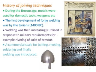
History of joiningtechniques
• During the Bronze age, metals were
used for domestic tools, weapons etc
• The first development of forge welding
was by the Syrians (1400 BC).
• Welding was then increasingly utilised in
response to military requirements for
example,riveting of suits of armour.
• A commercial scale for bolting, riveting,
soldering and finally
welding was introduced.
2
3.
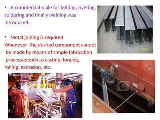
• A commercialscale for bolting, riveting,
soldering and finally welding was
introduced.
• Metal joining is required
Whenever the desired component cannot
be made by means of simple fabrication
processes such as casting, forging,
rolling, extrusion, etc.
3
4.
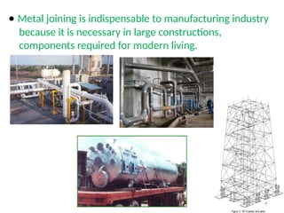
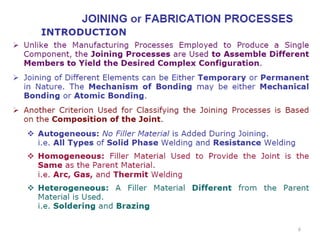
• Metal joiningis indispensable to manufacturing industry
because it is necessary in large constructions,
components required for modern living.
4
5.
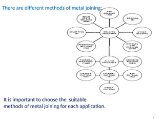
There are differentmethods of metal joining:
It is important to choose the suitable
methods of metal joining for each application.
5
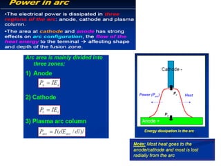
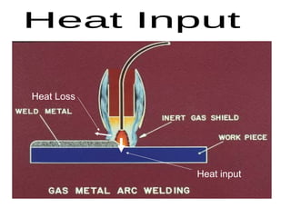
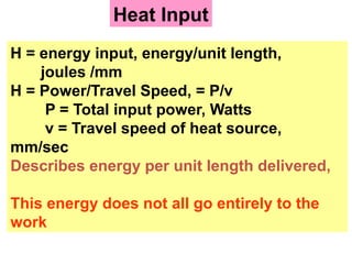
Heat Input
H =energy input, energy/unit length,
joules /mm
H = Power/Travel Speed, = P/v
P = Total input power, Watts
v = Travel speed of heat source,
mm/sec
Describes energy per unit length delivered,
This energy does not all go entirely to the
work
40.
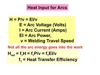
Heat Input forArcs
H = P/v = EI/v
E = Arc Voltage (Volts)
I = Arc Current (Amps)
EI = Arc Power,
v = Welding Travel Speed
Hnet = f1H = f1P/v = f1EI/v
f1 = Heat Transfer Efficiency
Not all the arc energy goes into the work
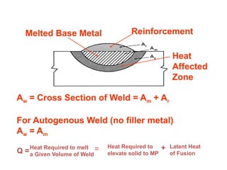
Reinforcement
Heat
Affected
Zone
Melted Base Metal
Aw= Cross Section of Weld = Am + Ar
For Autogenous Weld (no filler metal)
Aw = Am
Q =
Heat Required to
elevate solid to MP
+ Latent Heat
of Fusion
Heat Required to melt
a Given Volume of Weld
=
43.
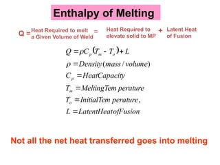
Enthalpy of Melting
Q=
Heat Required to
elevate solid to MP
+ Latent Heat
of Fusion
Heat Required to melt
a Given Volume of Weld
=
ofFusion
LatentHeat
L
perature
InitialTem
T
perature
MeltingTem
T
ty
HeatCapaci
C
volume
mass
Density
L
T
T
C
Q
o
m
p
o
m
p
,
)
/
(
Not all the net heat transferred goes into melting
44.
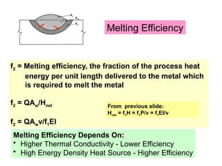
Melting Efficiency
f2 =Melting efficiency, the fraction of the process heat
energy per unit length delivered to the metal which
is required to melt the metal
f2 = QAw/Hnet
f2 = QAwv/f1EI
From previous slide:
Hnet = f1H = f1P/v = f1EI/v
Melting Efficiency Depends On:
• Higher Thermal Conductivity - Lower Efficiency
• High Energy Density Heat Source - Higher Efficiency
45.
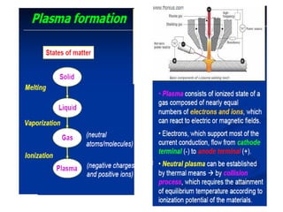
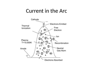
Current in theArc
Plasma
Electron
Ion
Neutral
Gas Atom
Ionization Free
Recombination
T>10,000K
Thermal
Cathode
Anode
Electrons Emitted
Electrons Absorbed
47.
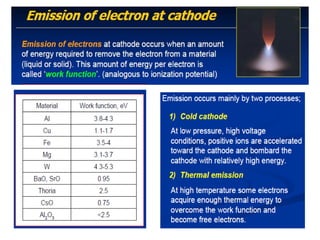
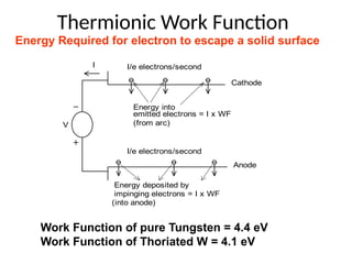
Thermionic Work Function
V
II/e electrons/second
Energy into
Cathode
Anode
emitted electrons = I x WF
Energy deposited by
impinging electrons = I x WF
I/e electrons/second
(from arc)
(into anode)
Energy Required for electron to escape a solid surface
Work Function of pure Tungsten = 4.4 eV
Work Function of Thoriated W = 4.1 eV
Self-Regulation of theArc
Vm
F
B
h
Contact
Tube or Tip
Feed Rolls
Wire Spool
or Reel
Wire
Feeder
CV
Power
Source
V
I
V
I
CV
I=F/k1
arc too
arc too
short
long
current
drops
current
rises
F=constant, I varies
B<F B>F
64.
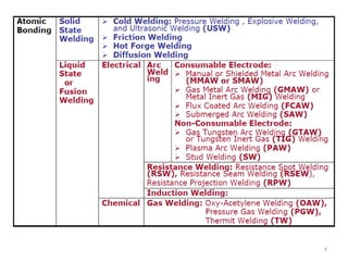
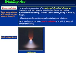
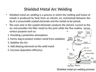
Shielded Metal ArcWelding
• Shielded metal arc welding is a process in which the melting and fusion of
metals is produced by heat from an electric arc maintained between the
tip of a consumable coated electrode and the metals to be joined.
• The core wire in the coated electrode conducts the electric current to the
arc and provides the filler metal to the joint while the flux coating serves
various purpose such as:
1. Providing a protective atmosphere
2. Forms slag to protect molten metal from oxidation
3. Stabilise the Arc
4. Add alloying elements to the weld metal
5. Increase deposition efficiency
Shielded metal arc welding process
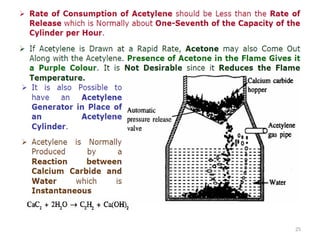
Typical Equipment ofResistance Spot Welding
(a) (b)
[Reference: Welding Process Slides, The Welding Institute]
77.
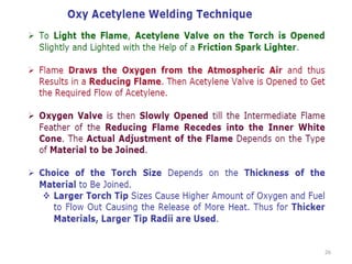
Process Operation ofResistance Spot
Welding
[Reference: Welding Process Slides, The Welding Institute]
78.
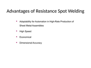
Advantages of ResistanceSpot Welding
Adaptability for Automation in High-Rate Production of
Sheet Metal Assemblies
High Speed
Economical
Dimensional Accuracy
79.
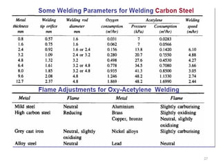
Basic Single ImpulseWelding Cycle
Electrode Force
Welding Current
Welding Cycle
Squeeze Time Weld Time Hold
Time
Off
Time
[Reference: Welding Handbook, Volume 2, AWS, p.538]
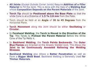
Temperature Gradient ofA Spot Weld
End of
“Weld Time”
20% of
“Weld Time”
Water
Temperature
Water
Water
Electrode
Electrode
Work
Welding Temperature
[Reference: Resistance Welding Manual, RWMA, p.1-4]
82.
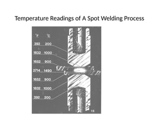
Temperature Readings ofA Spot Welding Process
This illustration was taken
about 4/60th of a second
after the welding current
starts.
83.
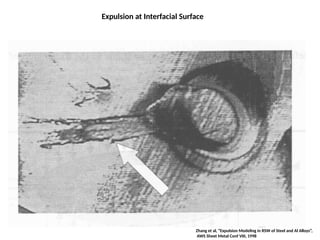
Expulsion at InterfacialSurface
Zhang et al, “Expulsion Modeling in RSW of Steel and Al Alloys”,
AWS Sheet Metal Conf VIII, 1998
84.
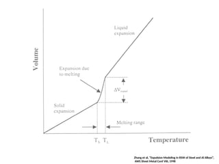
Zhang et al,“Expulsion Modeling in RSW of Steel and Al Alloys”,
AWS Sheet Metal Conf VIII, 1998
85.
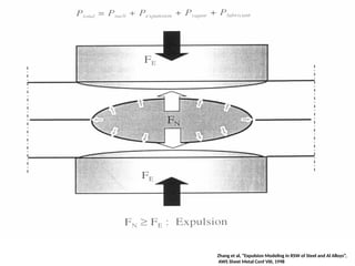
Zhang et al,“Expulsion Modeling in RSW of Steel and Al Alloys”,
AWS Sheet Metal Conf VIII, 1998
Editor's Notes
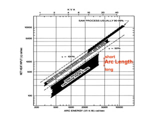
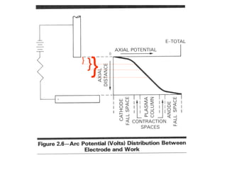
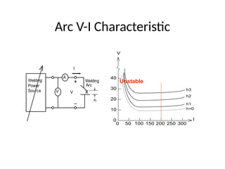
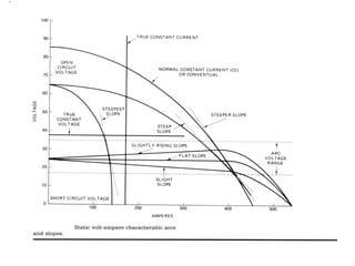
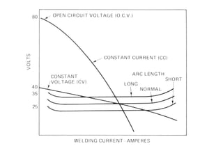
#49 The graphical method of voltage-current characteristics is very useful for the study of welding arcs. The voltage-current characteristic of an arc can be obtained by measuring arc current and voltage for different power source settings, while holding arc length constant. This is easy to do for a tungsten arc - more problematical for a metal arc. The characteristic differs greatly from the linear characteristic of an ideal resistor. The nonlinear characteristic of the arc makes graphical V-I analysis of arc circuits more appropriate than mathematical analysis. The characteristic rises to a high voltage at zero current, representing the voltage required to start the arc. The voltage to operate the arc drops with increasing current to around 100 amperes. It then rises at a slow rate. To some approximation over the medium current range, an arc almost operates at a constant voltage independent of current. This constant voltage tendency of the arc is one thing that makes it an unusual electrical load.
The arc characteristic raises and lowers with increase and decrease of arc length, respectively. As the arc length is made shorter and shorter, tending towards zero, the arc characteristic approaches a non-zero limiting voltage level.
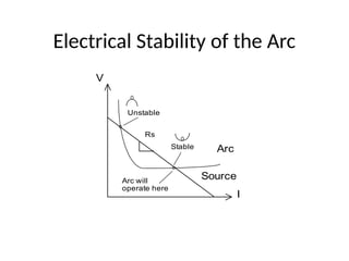
#51 A subtle electrical consideration associated with operating a welding arc has to do with the electrical stability of the operating point. This is not much of a factor with common electrical loads, but the nonlinear characteristic of the welding arc makes it a not insignificant factor in design of electrical systems for operating arcs.
Electrical stability requires that the power source characteristic have a droop, or slope, which falls off faster than that of the load. Since normal electrical circuits are characterized by constant resistance, with a slope that is positive, any power source with a voltage that falls off with current will produce a stable operating point. However, since an arc characteristic has a region of dropping voltage with current increase, an operating point may not be stable. An operating point is not stable where the arc characteristic is dropping faster than the source characteristic.
An electrically stable operating point is analogous to a ball sitting in a depression - if it is disturbed, it will role back to its original location. An electrically unstable operating point is like a ball sitting on a peak - if it is disturbed it will move away from its original point at a rate which will increase with time. The ball will move until it finds a stable point, where it will come to rest and stay. The same occurs with the arc system - it will only exist for any length of time at a stable operating point.
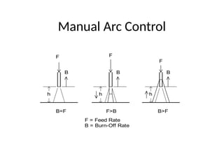
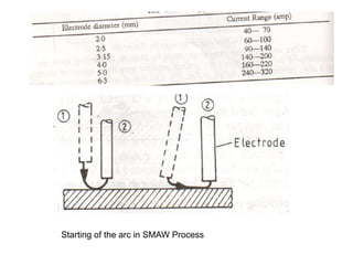
#53 With a manual arc, the welder controls the arc length by manipulating the electrode feed rate. The welder observes the arc and feeds the electrode faster to shorten the arc, and slower to lengthen the arc. The welders main objective is to maintain an optimum arc length. The optimum arc is as short as possible to concentrate the heat, without short-circuiting and erratic metal transfer.
The burn-off rate of the electrode is proportional to the arc current. Thus, with a constant current power source for manual welding, the electrode burn-off rate is fixed by the current setting. The welder controls the arc length via the feed rate of the electrode. To make the arc shorter, the welder feeds the electrode faster, such that feed rate exceeds the burn-off rate. To make the arc longer, the welder slows the electrode feed rate, such that it is less than the burn-off rate. Hand-and-eye coordination allows the arc length to be continuously maintained or adjusted by this process.
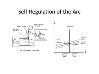
#54 When the control of electrode feed is automated, it is possible to maintain an arc with a constant voltage type of power source.
It is a relatively recent discovery in the history of arcs and welding arcs that a stable arc can be maintained with a constant voltage power source if the electrode is fed at a suitable constant speed. The electrode feed speed demands a current which is of the proper amount to melt off the electrode at an equal rate. If the current is not sufficient, the electrode will not melt-off fast enough and the arc length will decrease, or visa versa. This leads to regulation of the arc length as follows. If the arc is too long, the CV power source will deliver less current than required to melt off the wire at the required rate. This will cause the arc length to decrease with time, and the arc current to increase. Arc length will decrease until the current rises to provide a melt-off rate to match the feed rate. The opposite will occur if the arc length is too short. The arc length will thus regulate around the operating point where the current provides the required melt-off rate. It is found that a welding arc in such a manner is stable and usable for welding. The arc is said to self-regulate.
Most systems with automated wire feed, such as GMA, FCA, etc., use this phenomenon of self-regulation of the arc, and employ constant voltage power sources and constant speed electrode (wire) feeders.
#76 The machine shown in Figure (a) in this slide is typical of many resistance spot welding machines with a foot-operated control (D) which initiates both the pressure and current cycles. The type illustrated is a swinging arm machine, the top arm being pivoted. In other machines, the upper electrode assembly may be carried on a slide.
The workpieces shown in Figure (b) are placed between the electrodes which can be interchanged for different applications. The type illustrated is a typical method of joining stiffeners to thin sheet (0.5 mm) as shown here using 18 mm diameter electrodes with a tip diameter of 3.5 mm.
#77 The welding operation is automatic with preset controls, although the positioning of the workpiece may be manual. The electrodes are made of highly conducting material, so that resistance heating is concentrated at the joint interface. The area of concentration which determines the weld size is controlled by the area of the electrode faces. As the current is passed through the workpieces, pressure is applied to the electrode which keeps the faying surface in contact and excludes atmospheric contamination.
#78 Resistance spot welding is used extensively because it is a simple, inexpensive, versatile and forgiving process. It has also been shown to be adaptable to some degree of feedback control. Its high production rate, high speed, economical systems coupled with high dimensional accuracy, make it well suited for high production environments.
#79 The four phases welding cycle for spot, seam, and projection welding are: (1) Squeeze time - the time interval between timer initiation and the first application of current. The time interval is to assure that the electrodes contact the work and establish the full electrode force before welding current is applied. (2) Weld time - the time that welding current is applied to the work in making a weld in single-impulse welding. (3) Hold time - the time during which force is maintained to the work after the last impulse of current ends. During this time, the weld nugget solidifies and is cooled until it has adequate strength. (4) Off time - the time during which the electrodes are off the work and the work is moved to the next weld location. The term is generally applied where the welding cycle is repetitive.
The above slide shows a basic welding cycle. The use of one continuous application of current to make an individual weld is called single impulse welding. One or more of the following features may be added to this basic cycle to improve the physical and mechanical properties of the weld zone: (1) Precompression force to seat the electrodes and workpieces together. (2) Preheat to reduce the thermal gradient in the metal at the start of weld time. (3) Forging force to consolidate the weld nugget. (4) Quench and temper times to produce the desired weld strength properties in hardenable alloy steels. (5) Postheat to refine the weld grain size in steels. (6) Current decay to retard cooling on aluminum.
In some applications, the welding current is supplied intermittently during a weld interval time. The next slide shows the sequence of operation in a more complex welding cycle.
#80 If the power is applied over a time interval of t seconds, the heat energy developed in the resistance is:
Q = I2Rt (2)
where,
Q = Watt-seconds or joules.
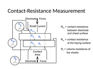
It is evident from equation (2) that the magnitude of the heat energy generated can be varied by changing the value of any of the three factors of the equation. The I and t can be readily varied by adjusting the welding control while R, the resistance of the workpieces being welded, is fixed for any one process. There are two types of electrical resistance present in the secondary circuit of a resistance welding machine: 1) the volume resistance of the material in the circuit, including the workpieces, and 2) the interfacial resistance of contacting surfaces. Each of these is discussed below.
All metals have some degree of resistance to the passage of current. The resistance offered to direct current is known as resistivity and is the resistance of a standard volume measured at a known temperature. It is a function of the material composition, and it varies with temperature. The resistance is greater to the passage of alternating current (AC) due to the presence of eddy current generated in the interior of the conductor. This is known as skin effect and increases with an increase in the frequency of the current and increase in the sectional area of the conductor. The [continued]
#81 All of the resistances involved in the machine secondary circuit are considered to be in series. Since the same current is passing through each one, the heat generated at any one location is proportional to the value of the resistance at that point. The heat energy generated at the weld faying surface is greater than that at any other localized point in the secondary circuit and, during the first part of the “weld time” interval, is responsible for most of the heat input to the weld zone. As the “weld time” progresses, the effective volume resistance of the weld zone increases as the temperature rises and accounts for a greater portion of the heat generated. The heat generated in the remainder of the secondary circuit is a loss and is dissipated by radiation, convection or conduction aided by water cooling. The above slide shows a typical setup. There are seven resistances connected in series. From the preceding statements, heat will be generated in each of these sections in proportion to the resistance of each. Because welding heat is wanted only at point 4, and efforts must be made to reduce the heat as much as possible at all other points. At the start of a weld the temperature at all parts is represented by the vertical line marked “water temperature”. The point of greatest resistance is 4, and heat is rapidly developed there. Points of next greatest resistance are 2 and 6, and the temperature rises rapidly at these points also, but not as fast as at point 4. At the end of about one-fifth of the total time allowed for the weld, the heat gradient corresponds to the extreme right-hand scalloped curve. It should be noted here that heat generated at 2 and 6 is rapidly dissipated into the contacting water-cooled electrodes 1 and 7, whereas the heat at 4 is partially trapped and dissipation is much slower. Therefore, as the “weld time” progresses, the rate of rise for point 4 will be much more rapid than 2 or 6.
#82 In order to better understand the nature of resistance welding and how heat generation is accomplished, it is best to consider a simple spot weld. The basic principles apply to all other resistance welding and heating methods except flash welding.
A spot weld is made by pressing two or more overlapping pieces of metal together while an electrical current is passed through a localized contact area. The electrical current heats the metal forming the weld nugget to the proper welding temperature.
One of the principles of resistance welding is to generate the heat energy in the weld zone very rapidly so that the minimum amount of heat will be dissipated by conduction to the cooler adjacent material. This requires a high rate of heat generation and is accomplished by bypassing a large value of current through the weld zone resistance for a short time interval. Another principle is to generate much more heat in the weld zone than in any other portion of the welding machine secondary circuit.
The theory and practice for achieving these two principles is stated as follows: heat energy is generated whenever an electrical current passes through an electrical resistance. The rate at which the heat is generated is given by:
W = I2R (1)
where,
W = Electrical power in watts.
I = Current in amperes.
R = Resistance in ohms. [continued]
#83 When welding current is too high or the welding time is too long, the nugget grows to an excessively large diameter,and the liquid, which expands upon melting producing an outward force, is no longer able to be held by the surrounding solid sheet. Expulsion occurs along the faying interface. Here we see the top sheet removed exposing the remains of liquid (now solidified into the whisker type flashing) which was expelled.
#84 There is some volume expansion that occurs when the spot weld nuggets are heated. When the temperature begins to heat the sheets, there is expansion of the solid as represented by temperatures lower than the solidus temperature Ts. In the melting range, there is a large volume expansion as the liquid is formed. And above this range, expansion in the liquid phase continues. This liquid expansion produces a large hydrostatic force within the molten region.
#85 Here is noted the balance of forces as the liquid expands. If the force in the nugget exceeds that of the force exerted by the electrode, expulsion occurs.
![Typical Equipment of Resistance Spot Welding
(a) (b)
[Reference: Welding Process Slides, The Welding Institute]](https://image.slidesharecdn.com/weldingprocesses-250722093545-d94def5c/85/Welding-processes-Explanation-in-details-76-320.jpg)
![Process Operation of Resistance Spot
Welding
[Reference: Welding Process Slides, The Welding Institute]](https://image.slidesharecdn.com/weldingprocesses-250722093545-d94def5c/85/Welding-processes-Explanation-in-details-77-320.jpg)
![Basic Single Impulse Welding Cycle
Electrode Force
Welding Current
Welding Cycle
Squeeze Time Weld Time Hold
Time
Off
Time
[Reference: Welding Handbook, Volume 2, AWS, p.538]](https://image.slidesharecdn.com/weldingprocesses-250722093545-d94def5c/85/Welding-processes-Explanation-in-details-79-320.jpg)
![Temperature Gradient of A Spot Weld
End of
“Weld Time”
20% of
“Weld Time”
Water
Temperature
Water
Water
Electrode
Electrode
Work
Welding Temperature
[Reference: Resistance Welding Manual, RWMA, p.1-4]](https://image.slidesharecdn.com/weldingprocesses-250722093545-d94def5c/85/Welding-processes-Explanation-in-details-81-320.jpg)