SlideShare a Scribd company logo
1 of 52
Welding
Welding processes 4-5 lectures
Metallurgical effect 4-5 lectures
Inspection and testing 1 lecture
A text book of welding technology: O. P. Khanna, Dhanpat Rai Publicaitons
Welding: A. C. Davies, CUP
The metallurgy of welding, D. Seferian, Chapman and Hall
Metallurgy of welding, J. F. Lancaster, Abington Publishing
Introduction to the physical metallurgy of welding, K. Easterling, B H
Principles of welding technology, L. M. Gourd, Viva Books Pvt Ltd
The Welding Institute website
What is welding?
Welding is a fabrication process that joins materials, usually metals or
thermoplastics, by causing coalescence.
“A weld is a union between pieces of metal at faces rendered plastic or
liquid by heat or by pressure or by both.” (British standard 499, Part1).
Sufficient strength can be produced in a weld only by interatomic
bonding. The primary function of welding is to provide link between
atoms at the interface of the joint.
•Surfaces must be in intimate contact: they should be atomically flat.
•Surface must be metallurgically clean (grease, paint, moisture,
oxygen, nitrogen).Dr.S.B.Singh:
Interatomic bond can be formed when
the surfaces are within the typical
Most welded joint are often made by melting the workpieces
and adding a filler material to form a pool of molten material
(the weld puddle or pool) that cools to become a strong joint.
Sometimes pressure is used in conjunction with heat, or by
itself, to produce the weld.
This is in contrast with soldering and brazing, which involve
melting a lower-melting-point material between the workpieces
to form a bond between them, without melting the workpieces.
Weld pool
CLASSIFICATION OF WELDING
PROCESSES
 Sources of heat, i.e., flame, arc, etc.
 Type of interaction i.e. liquid/liquid (fusion welding) or
solid/solid (solid state welding).
1. Gas Welding
• Air-acetylene Welding
• Oxy-acetylene Welding
• Oxy-hydrogen Welding
• Pressure gas Welding
2. Arc Welding
• Carbon Arc Welding
• Flux Cored Arc Welding
• TIG (or GTAW) Welding
• Plasma Arc Welding
• Electroslag Welding and Electro gas Welding
• Stud Arc Welding
• Shielded Metal Arc Welding
• Submerged Arc Welding
• MIG (or GMAW) Welding
3. Resistance Welding
• Spot Welding
• Seam Welding
• Projection Welding
• Flash Butt Welding
• High Frequency Resistance Welding
• Resistance Butt Welding
• Percussion Welding
4. Solid State Welding
• Cold Welding
• Explosive Welding
• Friction Welding
• Roll Welding
• Diffusion Welding
• Forge Welding
• Hot Pressure Welding
• Ultrasonic Welding
5. Thermo-Chemical Welding Processes
• Thermit Welding
• Atomic Hydrogen Welding
6. Radiant Energy Welding Processes
• Electron Beam Welding
• Laser Beam Welding
COMMONLY WELDED BASE METALS
1. Ferrous
• Wrought Iron
• Cast Iron
• Carbon Steel (Low, Medium and High Carbon Steels)
• Cast Steels
• Alloy Steels
• Stainless Steels, etc
2. Non-ferrous
• Aluminum and its alloys
• Copper and its alloys
• Magnesium and its alloys
• Nickel and its alloys
• Zinc and its alloys, etc
ADVANTAGES OF WELDING
• A good weld is as strong as the base metal.
• General welding equipment is not very costly.
• Portable welding equipments are available.
• Welding permits considerable freedom in design.
• A large number of metal/alloys both similar and dissimilar
can be joined by welding.
• Welding can join workpieces through spots, as continuous
pressure tight seams, end-to-end and in a number of other
configurations.
• Welding can be mechanized.
DISADVANTAGES OF WELDING
• Welding gives out harmful radiations (light), fumes and spatter.
• Welding results in residual stresses and distortion of the
workpieces.
• Jigs and fixtures are generally required to hold and position the
parts to be welded.
• Edge preparation of the workpieces is generally required before
welding them.
• A skilled welder is a must to produce a good welding job.
• Welding heat produces metallurgical changes. The structure of
the welded joint is not same as that of the parent metal.
• A welded joint, for many reasons, needs stress-relief heat-
treatment.
PRATICALAPPLICATIONS OF WELDING
1. Aircraft Construction 10. Ships
2. Automobile Construction 11. Machine tool frames,
3. Bridges cutting tools and dies
4. Buildings 12. Household and office
5. Pressure Vessels and Tanks furniture
6. Storage Tanks 13. Earth moving
7. Rail, Road Equipment machinery and cranes
8. Pipings and Pipelines
9. Trucks and trailers
FUSION WELDING
A source of heat to create localised fusion.
Fusion must be restricted to the joint line and should not be more than that required
to achieve bonding.
If the weld pool becomes too large, it is difficult to control and an unsatisfactory
weld is produced.
Overall heating should be restricted to a narrow band along each side of the weld.
Basic attributes of heat source:
The area heated directly by the heat source must be small so that the weld pool can
be limited to a manageable size.
• The heat source must operate at a temperature significantly higher than the melting
point of the metal being welded. If the differential is small, the rate of heat transfer
is low and heat is spread over a wider area of the joint before fusion is achieved.
• There must be an adequate heating capacity. The total amount of heat, or the rate at
which heat is required, depends not only on the physical properties of the metal but
also on the joint configuration and dimensions.
• The heat source itself must be capable of regulation, so conditions can be set to suit
the joint. These conditions must remain constant throughout.
HEAT SOURCES:
• An oxygen – fuel-gas flame
• An electric arc
• Resistance heating at an interface
• Resistance heating in a slag bath
• Chemical energy
• Electron beam / Laser beam
Filler Metal
When welding two pieces of metal together, a space is left between the joint. The
material that is added to fill this space during the welding
process is known as the filler metal or material. Composition: Same / similar.
Two types of filler metals commonly used in welding are
Welding rods and welding electrodes.
The term welding rod refers to a form of filler metal that does not conduct an electric
current during the welding process. The only purpose of a welding rod is to
supply filler metal to the joint. This type of filler metal is often used for gas welding.
In electric-arc welding, the term electrode refers to the component that conducts the
current from the electrode holder to the metal being welded. Electrodes are
classified into two groups: consumable and nonconsumable. Consumable
electrodes not only provide a path for the current but they also supply filler metal to the
joint. Nonconsumable electrodes are only used as a conductor for the electrical
current, such as in gas tungsten arc welding. The filler metal for gas tungsten arc
welding is a hand fed consumable welding rod.
Protection of Weld Pool:
• Weld pool exposed to open atmosphere absorbs O, N, H depending
on composition of parent metal.
• Presence of significant amounts of dissolved or combined gases is
undesirable, since it often results in the formation of gas pores or voids
in the completed weld.
• In addition, the properties or integrity of the joint can be impaired.
Oxides in metals give poor quality, low strength welds. Welding
impossible in some cases.
More examples: the ductility of aluminum weld metal is affected by
the existence of oxide films at the grain boundaries; the electrical
conductivity of copper is reduced by an increase in the oxygen
content; dissolved hydrogen in high-strength-steel weld metal can lead
to cracks in the joint.
• Any viable welding system must include some method of
preventing atmospheric contamination.
• Two basic techniques are employed:
1. Blanket the weld pool with molten FLUX, forming a
slag layer which is impervious to the passage of gases.
2. Replace the air in the vicinity of the heat source and weld
pool by a gas which does not react with the molten metal
and is therefore in this sense inert.
• A flux is a material used to prevent, dissolve or facilitate removal of oxides
and other undesirable substances. A flux prevents the oxidation of molten metal.
• The flux (material) is fusible and non-metallic.
• During welding, flux chemically reacts with the oxides and a slag is formed
that floats to and covers the top of the molten puddle of metal and thus helps
keep out atmospheric oxygen and other gases.
The fluxes usually come in the form of a paste, powder, or liquid. Powders can
be sprinkled on the base metal, or the filler rod can be heated and dipped
into the powder. Liquid and paste fluxes can be applied to the filler rod
and to the base metal with a brush. For shielded metal arc welding, the flux is on
the electrode.
After welding, the slag from over the welded joint can be removed by chipping,
filing or grinding.
Though no flux is usually used in gas welding of steel, it is essential for cast
iron, stainless steel, Al-alloys, Mg-alloys.
No single flux is satisfactory for universal use; however, there are a lot of good
general-purpose fluxes for use with common metals. In general, a good flux has the
following characteristics:
•It is fluid and active at the melting point of the filler metal.
•It remains stable and does not change to a vapor rapidly within the temperature
range of the welding procedure.
•It dissolves all oxides and removes them from the joint surfaces.
•It adheres to the metal surfaces while they are being heated and does not ball up or
blow away.
•It does not cause a glare that makes it difficult to see the progress of welding or
brazing.
•It is easy to remove after the joint is welded.
•It is available in an easily applied form.
Eg: Boric acid, borax, fluospar, Kcl, NaCl, etc.
CAUTION
Nearly all fluxes give off fumes that may be toxic. Use ONLY in well-
ventilated spaces. It is also good to remember that ALL welding operations require
adequate ventilation whether a flux is used or not.
Gas / Oxy-fuel welding
The heat needed to melt the metal comes from combustion of a
fuel gas and oxygen. The intense heat (flame) thus produced
melts and fuses together the edges of the parts to be welded,
generally with the addition of a filler metal.
Acetylene is the most commonly used fuel gas.
Other fuel gases: Hydrogen, propane, butane.
Principles of Operation:
• When acetylene is mixed with oxygen in correct proportions in the
welding torch and ignited and burnt at the tip of a specially designed
nozzle which is fitted to the torch body. The flame resulting at the tip
of the torch is sufficiently hot to melt and join the parent metal.
• The oxy-acetylene flame reaches a temperature of about 3200oC and
thus can melt all commercial metals which, during welding, actually
flow together to form a complete bond.
•A filler metal rod is generally added by manually feeding the wire to
the leading edge of the molten metal pool to build up the seam for
greater strength.
• Oxy-acetylene welding does not require the components to be forced
together under pressure until the weld forms and solidifies.
No sound
Loud hissing sound
Neutral Flame
• A neutral flame is produced when approximately equal volumes of
oxygen and acetylene are mixed in the welding torch and burnt at the
torch tip. (More accurately the oxygen-to-acetylene ratio is 1.1 to 1).
• The temperature of the neutral flame is of the order of about 3260oC.
• The flame has a nicely defined inner cone which is light blue in
colour. It is surrounded by an outer flame envelope.
• A neutral flame is named so because it effects no chemical change in
the molten metal and therefore will not oxidize or carburize the metal
• The neutral flame is commonly used for the welding of: Mild Steel,
Stainless Steel, Cast Iron, Copper, Aluminum
Oxidising Flame
An oxidising flame can be recognized by the small cone which is shorter, much bluer
in colour and more pointed than that of the neutral flame.
The outer flame envelope is much shorter and tends to fan out at the end; on the other
hand the neutral and reducing envelops tend to come to a sharp point.
• An oxidising flame burns with a decided loud roar.
• An oxidising flame tends to be hotter than the neutral flame. This is because of
excess oxygen and which causes the temperature to rise as high ~ 3500oC.
• The high temperature of an oxidizing flame (O2:C2H2 = 1.5:1) would be an
advantage if it were not for the fact that the excess oxygen, especially at high
temperatures, tends to combine with many metals to form hard, brittle, low strength
oxides. Moreover, an excess of oxygen causes the weld bead and the surrounding
area to have a scummy or dirty appearance.
• For these reasons, an oxidising flame is of limited use in welding. It is not used
in the welding of steel.
A slightly oxidising flame is helpful when welding most
(i) Copper-base metals, (ii) Zinc-base metals, and (iii) A few types
of ferrous metals, such as manganese steel and cast iron.
The oxidizing atmosphere, in these cases, creates a base-metal oxide
that protects the base metals. For example, in welding brass, the
zinc has a tendency to separate and fume away. The formation of a
covering copper oxide prevents the zinc from dissipating.
Reducing Flame
• If the volume of oxygen supplied to the neutral flame is reduced, the resulting
flame will be a carburising or reducing flame, i.e. rich in acetylene.
• A reducing flame can be recognized by acetylene feather which exists between the
inner cone and the outer envelope. The outer flame envelope is longer than that of
the neutral flame and is usually much brighter in colour.
• A reducing flame does not completely consume the available carbon; therefore, its
burning temperature is lower and the leftover carbon is forced into the molten metal.
With iron and steel it produces very hard, brittle substance known as iron carbide.
This chemical change makes the metal unfit for many applications in which the weld
may need to be bent or stretched. Metals that tend to absorb carbon should not be
welded with reducing flame.
• A reducing flame has an approximate temperature of (3000 oC).
Carburizing flame contains more acetylene than a reducing flame.
A carburizing flame is used in the welding of lead and for carburizing
(surface hardening) purposes.
A reducing flame, on the other hand, does not carburize the metal, rather
it ensures the absence of the oxidizing condition. It is used for welding
with low alloy steel rods and for welding those metals, (e.g. non-ferrous)
that do not tend to absorb carbon. This flame is very well used for
welding high carbon steel.
Chemistry of Oxy-acetylene Flame:
The maximum temperature of the oxy-acetylene flame is
3100-3500 oC.
Centre of heat concentration is near the extreme tip of the
white cone.
Combustion of gas mixture in two stages:
1. Inner Cone:
2C2H2 + 2O2 (cylinder) 4 CO + 2H2 + heat
2. Outer envelope:
4CO + 2H2 + 3O2 4 CO2 + 2H2O + heat
55 kJ / litre
acetylene
From air
The total quantity of heat produced depend on the amount of
acetylene burnt. If more heat is needed the flow rate of acetylene
has to be increased together with an increase in oxygen supply to
get the correct type of flame.
The entire amount of heat (55 kJ / l of acetylene) is not available
for fusion because of two-stage reaction. The highest temperature
is at the tip of the inner cone and for most efficient operation this
point should be just above the surface of the weld pool. Heat from
first stage (35 % or 19 kJ / l) is used to fuse the parent metal. Heat
from second stage preheats the area.
The rate of travel is slower than in arc welding: (1) the rate of heat
transfer is slow and (2) in arc welding heat is generated at parent
metal surface.
No sound
Loud hissing sound
Leftward Technique:
•The flame is pointed in the direction of the welding, it preheats the
edges of the joint.
• Good control and a neat appearance are characteristics of the leftward
method.
• Leftward technique is usually used on relatively thin metals, i.e.,
having thickness less than 5 mm.
• When workpiece thickness is over 3 mm, it is necessary to bevel the
plate edges to produce a V-joint so that good root fusion may be
achieved. The included angle of V-joint is 80-90o. This large volume
weld is uneconomical in terms of time, weld metal deposited and
quantity of gases used and may also over-distort the weldment when
welding thick materials. Long welding time also leads to overheating
of the weld area and thus the weld metal may have coarse grains.
Rightward Technique:
• A narrower V-groove (30o bevel or 60o included angle) can be utilized
than in leftward welding. This provides a greater control and reduced
welding costs.
• The rightward technique is one used on heavier or thicker (above 5
mm) base metals, because in this technique the heat is concentrated
into the metal. Welds with penetrations of approximately 12 mm can
be achieved in a single pass.
Rightward technique has advantages over leftward technique:
• Up to 8.2 mm plate thickness no bevel is necessary. This saves the
cost of preparation and reduces the consumption of filler rod.
• For welding bigger thicknesses, where bevelling of plate edges
becomes necessary, the included angle of V need be only 60o, which
requires less filler metal against 80oV preparation used in leftward
welding technique.
• The welder’s view of the weld pool and the sides and bottom of the V
groove is unobstructed. This results in better control and higher
welding speeds.
• The smaller total volume of deposited metal, as compared to leftward
welding, reduces shrinkage and distortion.
• The weld quality is better than that obtained with the leftward
technique.
• Owing to less consumption of the filler metal, the rightward technique
involves lower cost of welding than leftward technique.
ADVANTAGES OF GAS WELDING
• It is probably the most versatile process. It can be applied to a wide
variety of manufacturing and maintenance situations.
• Welder has considerable control over the temperature of the metal in
the weld zone. When the rate of heat input from the flame is properly
coordinated with the speed of welding, the size, viscosity and surface
tension of the weld puddle can be controlled, permitting the pressure
of the flame to be used to aid in positioning and shaping the weld.
• The rate of heating and cooling is relatively slow. In some cases,
this is an advantage.
• Since the sources of heat and of filler metal are separate, the welder
has control over filler-metal deposition rates. Heat can be applied
preferentially to the base metal or the filler metal.
• The equipment is versatile, low cost, self-sufficient and usually
portable. Besides gas welding, the equipment can be used for
preheating, postheating, braze welding, torch brazing and it is readily
converted to oxygen cutting.
• The cost and maintenance of the welding equipment is low when
compared to that of some other welding processes.
DISADVANTAGES OF GAS WELDING:
• Heavy sections cannot be joined economically.
• Flame temperature is less than the temperature of the arc.
• Fluxes used in certain welding and brazing operations produce fumes
that are irritating to the eyes, nose, throat and lungs.
• Refractory metals (e.g., tungsten, molybdenum, tantalum, etc.) and
reactive metals (e.g., titanium and zirconium) cannot be gas welded.
• Gas flame takes a long time to heat up the metal than an arc.
• Prolonged heating of the joint in gas welding results in a larger heat-
affected area. This often leads to increased grain growth, more
distortion and, in some cases, loss of corrosion resistance.
• More safety problems are associated with the handling and storing of
gases.
• Acetylene and oxygen gases are rather expensive.
• Flux shielding in gas welding is not so effective as an inert gas
shielding in TIG or MIG welding.
APPLICATIONS OF GAS WELDING
• For joining thin materials.
• For joining materials in whose case excessively high temperatures or
rapid heating and cooling of the job would produce unwanted or harmful
changes in the metal.
• For joining materials in whose case extremely high temperatures would
cause certain elements in the metal to escape into the atmosphere.
• For joining most ferrous and non-ferrous metals, e.g., carbon steels,
alloy steels, cast iron, aluminium, copper, nickel, magnesium and its
alloys, etc.
• In automotive and aircraft industries. In sheet metal fabricating plants,
etc.
Oxyacetylene 3200 oC
Oxyhydrogen 2500 oC (flame hardly visible)
Oxy-propane 2500 oC
Other fuel gases

More Related Content

Similar to fdocuments.in_welding-introduction.ppt

Joining processes (welding)
Joining processes (welding)Joining processes (welding)
Joining processes (welding)9665930613
 
Submerged arc welding
Submerged arc weldingSubmerged arc welding
Submerged arc weldingSamarth Sojitra
 
welding process.pptx
welding process.pptxwelding process.pptx
welding process.pptxbinitranjan8
 
Welding process,Manufacturing Process,Production Technology,Metal Joining Pro...
Welding process,Manufacturing Process,Production Technology,Metal Joining Pro...Welding process,Manufacturing Process,Production Technology,Metal Joining Pro...
Welding process,Manufacturing Process,Production Technology,Metal Joining Pro...Prof.Mayur Modi
 
arc welding.pptx
arc welding.pptxarc welding.pptx
arc welding.pptxvinothkumarh1
 
Unit ii JOINING PROCESSES
Unit   ii JOINING PROCESSESUnit   ii JOINING PROCESSES
Unit ii JOINING PROCESSESSelvamV17
 
Welding ppt
Welding pptWelding ppt
Welding pptnaik4u2002
 
WELDING.pptx
WELDING.pptxWELDING.pptx
WELDING.pptxCeejayJames1
 
As welding
As weldingAs welding
As weldingsharmaabhi
 
Types of welding
Types of welding Types of welding
Types of welding Sabik T S
 
Welding report Amar Askandar
Welding report Amar AskandarWelding report Amar Askandar
Welding report Amar AskandarAmar A.Mahmood
 
Welding & joining
Welding & joiningWelding & joining
Welding & joiningArup Nath
 
lecture 5 - Welding Processes 2019 (1).ppt
lecture 5 - Welding Processes 2019 (1).pptlecture 5 - Welding Processes 2019 (1).ppt
lecture 5 - Welding Processes 2019 (1).pptKAPEMBWAMAPALO
 
Welding Process 130120119126
Welding Process 130120119126Welding Process 130120119126
Welding Process 130120119126Pandya Kartik
 
Advanced welding
Advanced weldingAdvanced welding
Advanced weldingraajeeradha
 
Manufacturing Technology I
Manufacturing Technology I Manufacturing Technology I
Manufacturing Technology I Karthikeyan I
 

Similar to fdocuments.in_welding-introduction.ppt (20)

Joining processes (welding)
Joining processes (welding)Joining processes (welding)
Joining processes (welding)
 
Submerged arc welding
Submerged arc weldingSubmerged arc welding
Submerged arc welding
 
My presentation-welding
My presentation-weldingMy presentation-welding
My presentation-welding
 
welding process.pptx
welding process.pptxwelding process.pptx
welding process.pptx
 
Welding process,Manufacturing Process,Production Technology,Metal Joining Pro...
Welding process,Manufacturing Process,Production Technology,Metal Joining Pro...Welding process,Manufacturing Process,Production Technology,Metal Joining Pro...
Welding process,Manufacturing Process,Production Technology,Metal Joining Pro...
 
arc welding.pptx
arc welding.pptxarc welding.pptx
arc welding.pptx
 
Unit ii JOINING PROCESSES
Unit   ii JOINING PROCESSESUnit   ii JOINING PROCESSES
Unit ii JOINING PROCESSES
 
Welding ppt
Welding pptWelding ppt
Welding ppt
 
WELDING.pptx
WELDING.pptxWELDING.pptx
WELDING.pptx
 
As welding
As weldingAs welding
As welding
 
Types of welding
Types of welding Types of welding
Types of welding
 
Welding report Amar Askandar
Welding report Amar AskandarWelding report Amar Askandar
Welding report Amar Askandar
 
Welding & joining
Welding & joiningWelding & joining
Welding & joining
 
lecture 5 - Welding Processes 2019 (1).ppt
lecture 5 - Welding Processes 2019 (1).pptlecture 5 - Welding Processes 2019 (1).ppt
lecture 5 - Welding Processes 2019 (1).ppt
 
welding
weldingwelding
welding
 
Welding Defects.pdf
Welding Defects.pdfWelding Defects.pdf
Welding Defects.pdf
 
arc welding
arc weldingarc welding
arc welding
 
Welding Process 130120119126
Welding Process 130120119126Welding Process 130120119126
Welding Process 130120119126
 
Advanced welding
Advanced weldingAdvanced welding
Advanced welding
 
Manufacturing Technology I
Manufacturing Technology I Manufacturing Technology I
Manufacturing Technology I
 

More from Praveen Kumar

UNIT3-Special casting processmechanical.ppt
UNIT3-Special casting processmechanical.pptUNIT3-Special casting processmechanical.ppt
UNIT3-Special casting processmechanical.pptPraveen Kumar
 
UNIT3-Special casting processcasting.ppt
UNIT3-Special casting processcasting.pptUNIT3-Special casting processcasting.ppt
UNIT3-Special casting processcasting.pptPraveen Kumar
 
Unit-II Basic Mechanical Engineering.pptx
Unit-II Basic Mechanical Engineering.pptxUnit-II Basic Mechanical Engineering.pptx
Unit-II Basic Mechanical Engineering.pptxPraveen Kumar
 
UNIT3-Special casting processmechanica.ppt
UNIT3-Special casting processmechanica.pptUNIT3-Special casting processmechanica.ppt
UNIT3-Special casting processmechanica.pptPraveen Kumar
 
UNIT3-Special casting processmechanical.ppt
UNIT3-Special casting processmechanical.pptUNIT3-Special casting processmechanical.ppt
UNIT3-Special casting processmechanical.pptPraveen Kumar
 
Unit-I Basic Mechanical Engineering.pptx
Unit-I Basic Mechanical Engineering.pptxUnit-I Basic Mechanical Engineering.pptx
Unit-I Basic Mechanical Engineering.pptxPraveen Kumar
 
UNIT3-Special casting process mechanical.ppt
UNIT3-Special casting process mechanical.pptUNIT3-Special casting process mechanical.ppt
UNIT3-Special casting process mechanical.pptPraveen Kumar
 
UNIT1-CastingprocessPROCESSINTRODUCTION.ppt
UNIT1-CastingprocessPROCESSINTRODUCTION.pptUNIT1-CastingprocessPROCESSINTRODUCTION.ppt
UNIT1-CastingprocessPROCESSINTRODUCTION.pptPraveen Kumar
 
Basic Mechanical Engineeringrole of mechanical engineering society-MID-I - Co...
Basic Mechanical Engineeringrole of mechanical engineering society-MID-I - Co...Basic Mechanical Engineeringrole of mechanical engineering society-MID-I - Co...
Basic Mechanical Engineeringrole of mechanical engineering society-MID-I - Co...Praveen Kumar
 
UNIT1-Castingprocessriserdesign design gating elemnts.ppt
UNIT1-Castingprocessriserdesign design gating elemnts.pptUNIT1-Castingprocessriserdesign design gating elemnts.ppt
UNIT1-Castingprocessriserdesign design gating elemnts.pptPraveen Kumar
 
UNIT2-Solidificationcasting processsand.ppt
UNIT2-Solidificationcasting processsand.pptUNIT2-Solidificationcasting processsand.ppt
UNIT2-Solidificationcasting processsand.pptPraveen Kumar
 
Basic Mechanical Engineering-MID-I - Copy.pptx
Basic Mechanical Engineering-MID-I - Copy.pptxBasic Mechanical Engineering-MID-I - Copy.pptx
Basic Mechanical Engineering-MID-I - Copy.pptxPraveen Kumar
 
UNIT2-Solidificationcastingprocessmetal.ppt
UNIT2-Solidificationcastingprocessmetal.pptUNIT2-Solidificationcastingprocessmetal.ppt
UNIT2-Solidificationcastingprocessmetal.pptPraveen Kumar
 
UNIT2-RisersDESIGNCONSIDERATIONCASTING.ppt
UNIT2-RisersDESIGNCONSIDERATIONCASTING.pptUNIT2-RisersDESIGNCONSIDERATIONCASTING.ppt
UNIT2-RisersDESIGNCONSIDERATIONCASTING.pptPraveen Kumar
 
UNIT2-Risers casting desing considerations.ppt
UNIT2-Risers casting desing considerations.pptUNIT2-Risers casting desing considerations.ppt
UNIT2-Risers casting desing considerations.pptPraveen Kumar
 
UNIT2-Risers.castingdesignconsiderationppt
UNIT2-Risers.castingdesignconsiderationpptUNIT2-Risers.castingdesignconsiderationppt
UNIT2-Risers.castingdesignconsiderationpptPraveen Kumar
 
UNIT2-Risersdesignconsiderationscasting.ppt
UNIT2-Risersdesignconsiderationscasting.pptUNIT2-Risersdesignconsiderationscasting.ppt
UNIT2-Risersdesignconsiderationscasting.pptPraveen Kumar
 
UNIT2-Risersdesigncalculationcasting.ppt
UNIT2-Risersdesigncalculationcasting.pptUNIT2-Risersdesigncalculationcasting.ppt
UNIT2-Risersdesigncalculationcasting.pptPraveen Kumar
 
UNIT2-Risersdesign casting processriser.ppt
UNIT2-Risersdesign casting processriser.pptUNIT2-Risersdesign casting processriser.ppt
UNIT2-Risersdesign casting processriser.pptPraveen Kumar
 
UNIT2-Risers.casting process riser desingppt
UNIT2-Risers.casting process riser desingpptUNIT2-Risers.casting process riser desingppt
UNIT2-Risers.casting process riser desingpptPraveen Kumar
 

More from Praveen Kumar (20)

UNIT3-Special casting processmechanical.ppt
UNIT3-Special casting processmechanical.pptUNIT3-Special casting processmechanical.ppt
UNIT3-Special casting processmechanical.ppt
 
UNIT3-Special casting processcasting.ppt
UNIT3-Special casting processcasting.pptUNIT3-Special casting processcasting.ppt
UNIT3-Special casting processcasting.ppt
 
Unit-II Basic Mechanical Engineering.pptx
Unit-II Basic Mechanical Engineering.pptxUnit-II Basic Mechanical Engineering.pptx
Unit-II Basic Mechanical Engineering.pptx
 
UNIT3-Special casting processmechanica.ppt
UNIT3-Special casting processmechanica.pptUNIT3-Special casting processmechanica.ppt
UNIT3-Special casting processmechanica.ppt
 
UNIT3-Special casting processmechanical.ppt
UNIT3-Special casting processmechanical.pptUNIT3-Special casting processmechanical.ppt
UNIT3-Special casting processmechanical.ppt
 
Unit-I Basic Mechanical Engineering.pptx
Unit-I Basic Mechanical Engineering.pptxUnit-I Basic Mechanical Engineering.pptx
Unit-I Basic Mechanical Engineering.pptx
 
UNIT3-Special casting process mechanical.ppt
UNIT3-Special casting process mechanical.pptUNIT3-Special casting process mechanical.ppt
UNIT3-Special casting process mechanical.ppt
 
UNIT1-CastingprocessPROCESSINTRODUCTION.ppt
UNIT1-CastingprocessPROCESSINTRODUCTION.pptUNIT1-CastingprocessPROCESSINTRODUCTION.ppt
UNIT1-CastingprocessPROCESSINTRODUCTION.ppt
 
Basic Mechanical Engineeringrole of mechanical engineering society-MID-I - Co...
Basic Mechanical Engineeringrole of mechanical engineering society-MID-I - Co...Basic Mechanical Engineeringrole of mechanical engineering society-MID-I - Co...
Basic Mechanical Engineeringrole of mechanical engineering society-MID-I - Co...
 
UNIT1-Castingprocessriserdesign design gating elemnts.ppt
UNIT1-Castingprocessriserdesign design gating elemnts.pptUNIT1-Castingprocessriserdesign design gating elemnts.ppt
UNIT1-Castingprocessriserdesign design gating elemnts.ppt
 
UNIT2-Solidificationcasting processsand.ppt
UNIT2-Solidificationcasting processsand.pptUNIT2-Solidificationcasting processsand.ppt
UNIT2-Solidificationcasting processsand.ppt
 
Basic Mechanical Engineering-MID-I - Copy.pptx
Basic Mechanical Engineering-MID-I - Copy.pptxBasic Mechanical Engineering-MID-I - Copy.pptx
Basic Mechanical Engineering-MID-I - Copy.pptx
 
UNIT2-Solidificationcastingprocessmetal.ppt
UNIT2-Solidificationcastingprocessmetal.pptUNIT2-Solidificationcastingprocessmetal.ppt
UNIT2-Solidificationcastingprocessmetal.ppt
 
UNIT2-RisersDESIGNCONSIDERATIONCASTING.ppt
UNIT2-RisersDESIGNCONSIDERATIONCASTING.pptUNIT2-RisersDESIGNCONSIDERATIONCASTING.ppt
UNIT2-RisersDESIGNCONSIDERATIONCASTING.ppt
 
UNIT2-Risers casting desing considerations.ppt
UNIT2-Risers casting desing considerations.pptUNIT2-Risers casting desing considerations.ppt
UNIT2-Risers casting desing considerations.ppt
 
UNIT2-Risers.castingdesignconsiderationppt
UNIT2-Risers.castingdesignconsiderationpptUNIT2-Risers.castingdesignconsiderationppt
UNIT2-Risers.castingdesignconsiderationppt
 
UNIT2-Risersdesignconsiderationscasting.ppt
UNIT2-Risersdesignconsiderationscasting.pptUNIT2-Risersdesignconsiderationscasting.ppt
UNIT2-Risersdesignconsiderationscasting.ppt
 
UNIT2-Risersdesigncalculationcasting.ppt
UNIT2-Risersdesigncalculationcasting.pptUNIT2-Risersdesigncalculationcasting.ppt
UNIT2-Risersdesigncalculationcasting.ppt
 
UNIT2-Risersdesign casting processriser.ppt
UNIT2-Risersdesign casting processriser.pptUNIT2-Risersdesign casting processriser.ppt
UNIT2-Risersdesign casting processriser.ppt
 
UNIT2-Risers.casting process riser desingppt
UNIT2-Risers.casting process riser desingpptUNIT2-Risers.casting process riser desingppt
UNIT2-Risers.casting process riser desingppt
 

Recently uploaded

ZXCTN 5804 / ZTE PTN / ZTE POTN / ZTE 5804 PTN / ZTE POTN 5804 ( 100/200 GE Z...
ZXCTN 5804 / ZTE PTN / ZTE POTN / ZTE 5804 PTN / ZTE POTN 5804 ( 100/200 GE Z...ZXCTN 5804 / ZTE PTN / ZTE POTN / ZTE 5804 PTN / ZTE POTN 5804 ( 100/200 GE Z...
ZXCTN 5804 / ZTE PTN / ZTE POTN / ZTE 5804 PTN / ZTE POTN 5804 ( 100/200 GE Z...ZTE
 
Structural Analysis and Design of Foundations: A Comprehensive Handbook for S...
Structural Analysis and Design of Foundations: A Comprehensive Handbook for S...Structural Analysis and Design of Foundations: A Comprehensive Handbook for S...
Structural Analysis and Design of Foundations: A Comprehensive Handbook for S...Dr.Costas Sachpazis
 
What are the advantages and disadvantages of membrane structures.pptx
What are the advantages and disadvantages of membrane structures.pptxWhat are the advantages and disadvantages of membrane structures.pptx
What are the advantages and disadvantages of membrane structures.pptxwendy cai
 
247267395-1-Symmetric-and-distributed-shared-memory-architectures-ppt (1).ppt
247267395-1-Symmetric-and-distributed-shared-memory-architectures-ppt (1).ppt247267395-1-Symmetric-and-distributed-shared-memory-architectures-ppt (1).ppt
247267395-1-Symmetric-and-distributed-shared-memory-architectures-ppt (1).pptssuser5c9d4b1
 
Call Girls Service Nagpur Tanvi Call 7001035870 Meet With Nagpur Escorts
Call Girls Service Nagpur Tanvi Call 7001035870 Meet With Nagpur EscortsCall Girls Service Nagpur Tanvi Call 7001035870 Meet With Nagpur Escorts
Call Girls Service Nagpur Tanvi Call 7001035870 Meet With Nagpur EscortsCall Girls in Nagpur High Profile
 
Model Call Girl in Narela Delhi reach out to us at 🔝8264348440🔝
Model Call Girl in Narela Delhi reach out to us at 🔝8264348440🔝Model Call Girl in Narela Delhi reach out to us at 🔝8264348440🔝
Model Call Girl in Narela Delhi reach out to us at 🔝8264348440🔝soniya singh
 
Internship report on mechanical engineering
Internship report on mechanical engineeringInternship report on mechanical engineering
Internship report on mechanical engineeringmalavadedarshan25
 
Call Girls Delhi {Jodhpur} 9711199012 high profile service
Call Girls Delhi {Jodhpur} 9711199012 high profile serviceCall Girls Delhi {Jodhpur} 9711199012 high profile service
Call Girls Delhi {Jodhpur} 9711199012 high profile servicerehmti665
 
(ANVI) Koregaon Park Call Girls Just Call 7001035870 [ Cash on Delivery ] Pun...
(ANVI) Koregaon Park Call Girls Just Call 7001035870 [ Cash on Delivery ] Pun...(ANVI) Koregaon Park Call Girls Just Call 7001035870 [ Cash on Delivery ] Pun...
(ANVI) Koregaon Park Call Girls Just Call 7001035870 [ Cash on Delivery ] Pun...ranjana rawat
 
OSVC_Meta-Data based Simulation Automation to overcome Verification Challenge...
OSVC_Meta-Data based Simulation Automation to overcome Verification Challenge...OSVC_Meta-Data based Simulation Automation to overcome Verification Challenge...
OSVC_Meta-Data based Simulation Automation to overcome Verification Challenge...Soham Mondal
 
Analog to Digital and Digital to Analog Converter
Analog to Digital and Digital to Analog ConverterAnalog to Digital and Digital to Analog Converter
Analog to Digital and Digital to Analog ConverterAbhinavSharma374939
 
Current Transformer Drawing and GTP for MSETCL
Current Transformer Drawing and GTP for MSETCLCurrent Transformer Drawing and GTP for MSETCL
Current Transformer Drawing and GTP for MSETCLDeelipZope
 
High Profile Call Girls Nashik Megha 7001305949 Independent Escort Service Na...
High Profile Call Girls Nashik Megha 7001305949 Independent Escort Service Na...High Profile Call Girls Nashik Megha 7001305949 Independent Escort Service Na...
High Profile Call Girls Nashik Megha 7001305949 Independent Escort Service Na...Call Girls in Nagpur High Profile
 
Porous Ceramics seminar and technical writing
Porous Ceramics seminar and technical writingPorous Ceramics seminar and technical writing
Porous Ceramics seminar and technical writingrakeshbaidya232001
 
APPLICATIONS-AC/DC DRIVES-OPERATING CHARACTERISTICS
APPLICATIONS-AC/DC DRIVES-OPERATING CHARACTERISTICSAPPLICATIONS-AC/DC DRIVES-OPERATING CHARACTERISTICS
APPLICATIONS-AC/DC DRIVES-OPERATING CHARACTERISTICSKurinjimalarL3
 
Processing & Properties of Floor and Wall Tiles.pptx
Processing & Properties of Floor and Wall Tiles.pptxProcessing & Properties of Floor and Wall Tiles.pptx
Processing & Properties of Floor and Wall Tiles.pptxpranjaldaimarysona
 
Introduction to IEEE STANDARDS and its different types.pptx
Introduction to IEEE STANDARDS and its different types.pptxIntroduction to IEEE STANDARDS and its different types.pptx
Introduction to IEEE STANDARDS and its different types.pptxupamatechverse
 
(ANJALI) Dange Chowk Call Girls Just Call 7001035870 [ Cash on Delivery ] Pun...
(ANJALI) Dange Chowk Call Girls Just Call 7001035870 [ Cash on Delivery ] Pun...(ANJALI) Dange Chowk Call Girls Just Call 7001035870 [ Cash on Delivery ] Pun...
(ANJALI) Dange Chowk Call Girls Just Call 7001035870 [ Cash on Delivery ] Pun...ranjana rawat
 

Recently uploaded (20)

ZXCTN 5804 / ZTE PTN / ZTE POTN / ZTE 5804 PTN / ZTE POTN 5804 ( 100/200 GE Z...
ZXCTN 5804 / ZTE PTN / ZTE POTN / ZTE 5804 PTN / ZTE POTN 5804 ( 100/200 GE Z...ZXCTN 5804 / ZTE PTN / ZTE POTN / ZTE 5804 PTN / ZTE POTN 5804 ( 100/200 GE Z...
ZXCTN 5804 / ZTE PTN / ZTE POTN / ZTE 5804 PTN / ZTE POTN 5804 ( 100/200 GE Z...
 
Structural Analysis and Design of Foundations: A Comprehensive Handbook for S...
Structural Analysis and Design of Foundations: A Comprehensive Handbook for S...Structural Analysis and Design of Foundations: A Comprehensive Handbook for S...
Structural Analysis and Design of Foundations: A Comprehensive Handbook for S...
 
What are the advantages and disadvantages of membrane structures.pptx
What are the advantages and disadvantages of membrane structures.pptxWhat are the advantages and disadvantages of membrane structures.pptx
What are the advantages and disadvantages of membrane structures.pptx
 
247267395-1-Symmetric-and-distributed-shared-memory-architectures-ppt (1).ppt
247267395-1-Symmetric-and-distributed-shared-memory-architectures-ppt (1).ppt247267395-1-Symmetric-and-distributed-shared-memory-architectures-ppt (1).ppt
247267395-1-Symmetric-and-distributed-shared-memory-architectures-ppt (1).ppt
 
Exploring_Network_Security_with_JA3_by_Rakesh Seal.pptx
Exploring_Network_Security_with_JA3_by_Rakesh Seal.pptxExploring_Network_Security_with_JA3_by_Rakesh Seal.pptx
Exploring_Network_Security_with_JA3_by_Rakesh Seal.pptx
 
Call Girls Service Nagpur Tanvi Call 7001035870 Meet With Nagpur Escorts
Call Girls Service Nagpur Tanvi Call 7001035870 Meet With Nagpur EscortsCall Girls Service Nagpur Tanvi Call 7001035870 Meet With Nagpur Escorts
Call Girls Service Nagpur Tanvi Call 7001035870 Meet With Nagpur Escorts
 
Model Call Girl in Narela Delhi reach out to us at 🔝8264348440🔝
Model Call Girl in Narela Delhi reach out to us at 🔝8264348440🔝Model Call Girl in Narela Delhi reach out to us at 🔝8264348440🔝
Model Call Girl in Narela Delhi reach out to us at 🔝8264348440🔝
 
9953056974 Call Girls In South Ex, Escorts (Delhi) NCR.pdf
9953056974 Call Girls In South Ex, Escorts (Delhi) NCR.pdf9953056974 Call Girls In South Ex, Escorts (Delhi) NCR.pdf
9953056974 Call Girls In South Ex, Escorts (Delhi) NCR.pdf
 
Internship report on mechanical engineering
Internship report on mechanical engineeringInternship report on mechanical engineering
Internship report on mechanical engineering
 
Call Girls Delhi {Jodhpur} 9711199012 high profile service
Call Girls Delhi {Jodhpur} 9711199012 high profile serviceCall Girls Delhi {Jodhpur} 9711199012 high profile service
Call Girls Delhi {Jodhpur} 9711199012 high profile service
 
(ANVI) Koregaon Park Call Girls Just Call 7001035870 [ Cash on Delivery ] Pun...
(ANVI) Koregaon Park Call Girls Just Call 7001035870 [ Cash on Delivery ] Pun...(ANVI) Koregaon Park Call Girls Just Call 7001035870 [ Cash on Delivery ] Pun...
(ANVI) Koregaon Park Call Girls Just Call 7001035870 [ Cash on Delivery ] Pun...
 
OSVC_Meta-Data based Simulation Automation to overcome Verification Challenge...
OSVC_Meta-Data based Simulation Automation to overcome Verification Challenge...OSVC_Meta-Data based Simulation Automation to overcome Verification Challenge...
OSVC_Meta-Data based Simulation Automation to overcome Verification Challenge...
 
Analog to Digital and Digital to Analog Converter
Analog to Digital and Digital to Analog ConverterAnalog to Digital and Digital to Analog Converter
Analog to Digital and Digital to Analog Converter
 
Current Transformer Drawing and GTP for MSETCL
Current Transformer Drawing and GTP for MSETCLCurrent Transformer Drawing and GTP for MSETCL
Current Transformer Drawing and GTP for MSETCL
 
High Profile Call Girls Nashik Megha 7001305949 Independent Escort Service Na...
High Profile Call Girls Nashik Megha 7001305949 Independent Escort Service Na...High Profile Call Girls Nashik Megha 7001305949 Independent Escort Service Na...
High Profile Call Girls Nashik Megha 7001305949 Independent Escort Service Na...
 
Porous Ceramics seminar and technical writing
Porous Ceramics seminar and technical writingPorous Ceramics seminar and technical writing
Porous Ceramics seminar and technical writing
 
APPLICATIONS-AC/DC DRIVES-OPERATING CHARACTERISTICS
APPLICATIONS-AC/DC DRIVES-OPERATING CHARACTERISTICSAPPLICATIONS-AC/DC DRIVES-OPERATING CHARACTERISTICS
APPLICATIONS-AC/DC DRIVES-OPERATING CHARACTERISTICS
 
Processing & Properties of Floor and Wall Tiles.pptx
Processing & Properties of Floor and Wall Tiles.pptxProcessing & Properties of Floor and Wall Tiles.pptx
Processing & Properties of Floor and Wall Tiles.pptx
 
Introduction to IEEE STANDARDS and its different types.pptx
Introduction to IEEE STANDARDS and its different types.pptxIntroduction to IEEE STANDARDS and its different types.pptx
Introduction to IEEE STANDARDS and its different types.pptx
 
(ANJALI) Dange Chowk Call Girls Just Call 7001035870 [ Cash on Delivery ] Pun...
(ANJALI) Dange Chowk Call Girls Just Call 7001035870 [ Cash on Delivery ] Pun...(ANJALI) Dange Chowk Call Girls Just Call 7001035870 [ Cash on Delivery ] Pun...
(ANJALI) Dange Chowk Call Girls Just Call 7001035870 [ Cash on Delivery ] Pun...
 

fdocuments.in_welding-introduction.ppt

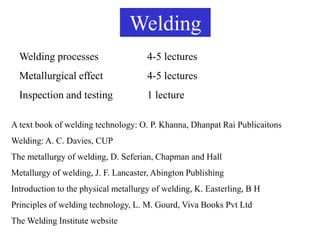
  • 1. Welding Welding processes 4-5 lectures Metallurgical effect 4-5 lectures Inspection and testing 1 lecture A text book of welding technology: O. P. Khanna, Dhanpat Rai Publicaitons Welding: A. C. Davies, CUP The metallurgy of welding, D. Seferian, Chapman and Hall Metallurgy of welding, J. F. Lancaster, Abington Publishing Introduction to the physical metallurgy of welding, K. Easterling, B H Principles of welding technology, L. M. Gourd, Viva Books Pvt Ltd The Welding Institute website
  • 2. What is welding? Welding is a fabrication process that joins materials, usually metals or thermoplastics, by causing coalescence. “A weld is a union between pieces of metal at faces rendered plastic or liquid by heat or by pressure or by both.” (British standard 499, Part1). Sufficient strength can be produced in a weld only by interatomic bonding. The primary function of welding is to provide link between atoms at the interface of the joint. •Surfaces must be in intimate contact: they should be atomically flat. •Surface must be metallurgically clean (grease, paint, moisture, oxygen, nitrogen).Dr.S.B.Singh: Interatomic bond can be formed when the surfaces are within the typical
  • 3. Most welded joint are often made by melting the workpieces and adding a filler material to form a pool of molten material (the weld puddle or pool) that cools to become a strong joint. Sometimes pressure is used in conjunction with heat, or by itself, to produce the weld. This is in contrast with soldering and brazing, which involve melting a lower-melting-point material between the workpieces to form a bond between them, without melting the workpieces.
  • 5.
  • 6. CLASSIFICATION OF WELDING PROCESSES  Sources of heat, i.e., flame, arc, etc.  Type of interaction i.e. liquid/liquid (fusion welding) or solid/solid (solid state welding). 1. Gas Welding • Air-acetylene Welding • Oxy-acetylene Welding • Oxy-hydrogen Welding • Pressure gas Welding
  • 7. 2. Arc Welding • Carbon Arc Welding • Flux Cored Arc Welding • TIG (or GTAW) Welding • Plasma Arc Welding • Electroslag Welding and Electro gas Welding • Stud Arc Welding • Shielded Metal Arc Welding • Submerged Arc Welding • MIG (or GMAW) Welding
  • 8. 3. Resistance Welding • Spot Welding • Seam Welding • Projection Welding • Flash Butt Welding • High Frequency Resistance Welding • Resistance Butt Welding • Percussion Welding
  • 9. 4. Solid State Welding • Cold Welding • Explosive Welding • Friction Welding • Roll Welding • Diffusion Welding • Forge Welding • Hot Pressure Welding • Ultrasonic Welding
  • 10. 5. Thermo-Chemical Welding Processes • Thermit Welding • Atomic Hydrogen Welding 6. Radiant Energy Welding Processes • Electron Beam Welding • Laser Beam Welding
  • 11.
  • 12. COMMONLY WELDED BASE METALS 1. Ferrous • Wrought Iron • Cast Iron • Carbon Steel (Low, Medium and High Carbon Steels) • Cast Steels • Alloy Steels • Stainless Steels, etc
  • 13. 2. Non-ferrous • Aluminum and its alloys • Copper and its alloys • Magnesium and its alloys • Nickel and its alloys • Zinc and its alloys, etc
  • 14. ADVANTAGES OF WELDING • A good weld is as strong as the base metal. • General welding equipment is not very costly. • Portable welding equipments are available. • Welding permits considerable freedom in design. • A large number of metal/alloys both similar and dissimilar can be joined by welding. • Welding can join workpieces through spots, as continuous pressure tight seams, end-to-end and in a number of other configurations. • Welding can be mechanized.
  • 15. DISADVANTAGES OF WELDING • Welding gives out harmful radiations (light), fumes and spatter. • Welding results in residual stresses and distortion of the workpieces. • Jigs and fixtures are generally required to hold and position the parts to be welded. • Edge preparation of the workpieces is generally required before welding them. • A skilled welder is a must to produce a good welding job. • Welding heat produces metallurgical changes. The structure of the welded joint is not same as that of the parent metal. • A welded joint, for many reasons, needs stress-relief heat- treatment.
  • 16. PRATICALAPPLICATIONS OF WELDING 1. Aircraft Construction 10. Ships 2. Automobile Construction 11. Machine tool frames, 3. Bridges cutting tools and dies 4. Buildings 12. Household and office 5. Pressure Vessels and Tanks furniture 6. Storage Tanks 13. Earth moving 7. Rail, Road Equipment machinery and cranes 8. Pipings and Pipelines 9. Trucks and trailers
  • 17.
  • 18.
  • 19.
  • 20.
  • 21.
  • 22. FUSION WELDING A source of heat to create localised fusion. Fusion must be restricted to the joint line and should not be more than that required to achieve bonding. If the weld pool becomes too large, it is difficult to control and an unsatisfactory weld is produced. Overall heating should be restricted to a narrow band along each side of the weld.
  • 23. Basic attributes of heat source: The area heated directly by the heat source must be small so that the weld pool can be limited to a manageable size. • The heat source must operate at a temperature significantly higher than the melting point of the metal being welded. If the differential is small, the rate of heat transfer is low and heat is spread over a wider area of the joint before fusion is achieved. • There must be an adequate heating capacity. The total amount of heat, or the rate at which heat is required, depends not only on the physical properties of the metal but also on the joint configuration and dimensions. • The heat source itself must be capable of regulation, so conditions can be set to suit the joint. These conditions must remain constant throughout.
  • 24. HEAT SOURCES: • An oxygen – fuel-gas flame • An electric arc • Resistance heating at an interface • Resistance heating in a slag bath • Chemical energy • Electron beam / Laser beam
  • 25. Filler Metal When welding two pieces of metal together, a space is left between the joint. The material that is added to fill this space during the welding process is known as the filler metal or material. Composition: Same / similar. Two types of filler metals commonly used in welding are Welding rods and welding electrodes. The term welding rod refers to a form of filler metal that does not conduct an electric current during the welding process. The only purpose of a welding rod is to supply filler metal to the joint. This type of filler metal is often used for gas welding. In electric-arc welding, the term electrode refers to the component that conducts the current from the electrode holder to the metal being welded. Electrodes are classified into two groups: consumable and nonconsumable. Consumable electrodes not only provide a path for the current but they also supply filler metal to the joint. Nonconsumable electrodes are only used as a conductor for the electrical current, such as in gas tungsten arc welding. The filler metal for gas tungsten arc welding is a hand fed consumable welding rod.
  • 26. Protection of Weld Pool: • Weld pool exposed to open atmosphere absorbs O, N, H depending on composition of parent metal. • Presence of significant amounts of dissolved or combined gases is undesirable, since it often results in the formation of gas pores or voids in the completed weld. • In addition, the properties or integrity of the joint can be impaired. Oxides in metals give poor quality, low strength welds. Welding impossible in some cases. More examples: the ductility of aluminum weld metal is affected by the existence of oxide films at the grain boundaries; the electrical conductivity of copper is reduced by an increase in the oxygen content; dissolved hydrogen in high-strength-steel weld metal can lead to cracks in the joint.
  • 27. • Any viable welding system must include some method of preventing atmospheric contamination. • Two basic techniques are employed: 1. Blanket the weld pool with molten FLUX, forming a slag layer which is impervious to the passage of gases. 2. Replace the air in the vicinity of the heat source and weld pool by a gas which does not react with the molten metal and is therefore in this sense inert.
  • 28. • A flux is a material used to prevent, dissolve or facilitate removal of oxides and other undesirable substances. A flux prevents the oxidation of molten metal. • The flux (material) is fusible and non-metallic. • During welding, flux chemically reacts with the oxides and a slag is formed that floats to and covers the top of the molten puddle of metal and thus helps keep out atmospheric oxygen and other gases. The fluxes usually come in the form of a paste, powder, or liquid. Powders can be sprinkled on the base metal, or the filler rod can be heated and dipped into the powder. Liquid and paste fluxes can be applied to the filler rod and to the base metal with a brush. For shielded metal arc welding, the flux is on the electrode. After welding, the slag from over the welded joint can be removed by chipping, filing or grinding. Though no flux is usually used in gas welding of steel, it is essential for cast iron, stainless steel, Al-alloys, Mg-alloys.
  • 29. No single flux is satisfactory for universal use; however, there are a lot of good general-purpose fluxes for use with common metals. In general, a good flux has the following characteristics: •It is fluid and active at the melting point of the filler metal. •It remains stable and does not change to a vapor rapidly within the temperature range of the welding procedure. •It dissolves all oxides and removes them from the joint surfaces. •It adheres to the metal surfaces while they are being heated and does not ball up or blow away. •It does not cause a glare that makes it difficult to see the progress of welding or brazing. •It is easy to remove after the joint is welded. •It is available in an easily applied form. Eg: Boric acid, borax, fluospar, Kcl, NaCl, etc. CAUTION Nearly all fluxes give off fumes that may be toxic. Use ONLY in well- ventilated spaces. It is also good to remember that ALL welding operations require adequate ventilation whether a flux is used or not.
  • 30. Gas / Oxy-fuel welding The heat needed to melt the metal comes from combustion of a fuel gas and oxygen. The intense heat (flame) thus produced melts and fuses together the edges of the parts to be welded, generally with the addition of a filler metal. Acetylene is the most commonly used fuel gas. Other fuel gases: Hydrogen, propane, butane.
  • 31. Principles of Operation: • When acetylene is mixed with oxygen in correct proportions in the welding torch and ignited and burnt at the tip of a specially designed nozzle which is fitted to the torch body. The flame resulting at the tip of the torch is sufficiently hot to melt and join the parent metal. • The oxy-acetylene flame reaches a temperature of about 3200oC and thus can melt all commercial metals which, during welding, actually flow together to form a complete bond. •A filler metal rod is generally added by manually feeding the wire to the leading edge of the molten metal pool to build up the seam for greater strength. • Oxy-acetylene welding does not require the components to be forced together under pressure until the weld forms and solidifies.
  • 32.
  • 33.
  • 34.
  • 35.
  • 37. Neutral Flame • A neutral flame is produced when approximately equal volumes of oxygen and acetylene are mixed in the welding torch and burnt at the torch tip. (More accurately the oxygen-to-acetylene ratio is 1.1 to 1). • The temperature of the neutral flame is of the order of about 3260oC. • The flame has a nicely defined inner cone which is light blue in colour. It is surrounded by an outer flame envelope. • A neutral flame is named so because it effects no chemical change in the molten metal and therefore will not oxidize or carburize the metal • The neutral flame is commonly used for the welding of: Mild Steel, Stainless Steel, Cast Iron, Copper, Aluminum
  • 38. Oxidising Flame An oxidising flame can be recognized by the small cone which is shorter, much bluer in colour and more pointed than that of the neutral flame. The outer flame envelope is much shorter and tends to fan out at the end; on the other hand the neutral and reducing envelops tend to come to a sharp point. • An oxidising flame burns with a decided loud roar. • An oxidising flame tends to be hotter than the neutral flame. This is because of excess oxygen and which causes the temperature to rise as high ~ 3500oC. • The high temperature of an oxidizing flame (O2:C2H2 = 1.5:1) would be an advantage if it were not for the fact that the excess oxygen, especially at high temperatures, tends to combine with many metals to form hard, brittle, low strength oxides. Moreover, an excess of oxygen causes the weld bead and the surrounding area to have a scummy or dirty appearance. • For these reasons, an oxidising flame is of limited use in welding. It is not used in the welding of steel.
  • 39. A slightly oxidising flame is helpful when welding most (i) Copper-base metals, (ii) Zinc-base metals, and (iii) A few types of ferrous metals, such as manganese steel and cast iron. The oxidizing atmosphere, in these cases, creates a base-metal oxide that protects the base metals. For example, in welding brass, the zinc has a tendency to separate and fume away. The formation of a covering copper oxide prevents the zinc from dissipating.
  • 40. Reducing Flame • If the volume of oxygen supplied to the neutral flame is reduced, the resulting flame will be a carburising or reducing flame, i.e. rich in acetylene. • A reducing flame can be recognized by acetylene feather which exists between the inner cone and the outer envelope. The outer flame envelope is longer than that of the neutral flame and is usually much brighter in colour. • A reducing flame does not completely consume the available carbon; therefore, its burning temperature is lower and the leftover carbon is forced into the molten metal. With iron and steel it produces very hard, brittle substance known as iron carbide. This chemical change makes the metal unfit for many applications in which the weld may need to be bent or stretched. Metals that tend to absorb carbon should not be welded with reducing flame. • A reducing flame has an approximate temperature of (3000 oC).
  • 41. Carburizing flame contains more acetylene than a reducing flame. A carburizing flame is used in the welding of lead and for carburizing (surface hardening) purposes. A reducing flame, on the other hand, does not carburize the metal, rather it ensures the absence of the oxidizing condition. It is used for welding with low alloy steel rods and for welding those metals, (e.g. non-ferrous) that do not tend to absorb carbon. This flame is very well used for welding high carbon steel.
  • 42. Chemistry of Oxy-acetylene Flame: The maximum temperature of the oxy-acetylene flame is 3100-3500 oC. Centre of heat concentration is near the extreme tip of the white cone. Combustion of gas mixture in two stages: 1. Inner Cone: 2C2H2 + 2O2 (cylinder) 4 CO + 2H2 + heat 2. Outer envelope: 4CO + 2H2 + 3O2 4 CO2 + 2H2O + heat 55 kJ / litre acetylene From air
  • 43. The total quantity of heat produced depend on the amount of acetylene burnt. If more heat is needed the flow rate of acetylene has to be increased together with an increase in oxygen supply to get the correct type of flame. The entire amount of heat (55 kJ / l of acetylene) is not available for fusion because of two-stage reaction. The highest temperature is at the tip of the inner cone and for most efficient operation this point should be just above the surface of the weld pool. Heat from first stage (35 % or 19 kJ / l) is used to fuse the parent metal. Heat from second stage preheats the area. The rate of travel is slower than in arc welding: (1) the rate of heat transfer is slow and (2) in arc welding heat is generated at parent metal surface.
  • 45.
  • 46. Leftward Technique: •The flame is pointed in the direction of the welding, it preheats the edges of the joint. • Good control and a neat appearance are characteristics of the leftward method. • Leftward technique is usually used on relatively thin metals, i.e., having thickness less than 5 mm. • When workpiece thickness is over 3 mm, it is necessary to bevel the plate edges to produce a V-joint so that good root fusion may be achieved. The included angle of V-joint is 80-90o. This large volume weld is uneconomical in terms of time, weld metal deposited and quantity of gases used and may also over-distort the weldment when welding thick materials. Long welding time also leads to overheating of the weld area and thus the weld metal may have coarse grains.
  • 47. Rightward Technique: • A narrower V-groove (30o bevel or 60o included angle) can be utilized than in leftward welding. This provides a greater control and reduced welding costs. • The rightward technique is one used on heavier or thicker (above 5 mm) base metals, because in this technique the heat is concentrated into the metal. Welds with penetrations of approximately 12 mm can be achieved in a single pass. Rightward technique has advantages over leftward technique: • Up to 8.2 mm plate thickness no bevel is necessary. This saves the cost of preparation and reduces the consumption of filler rod. • For welding bigger thicknesses, where bevelling of plate edges becomes necessary, the included angle of V need be only 60o, which requires less filler metal against 80oV preparation used in leftward welding technique.
  • 48. • The welder’s view of the weld pool and the sides and bottom of the V groove is unobstructed. This results in better control and higher welding speeds. • The smaller total volume of deposited metal, as compared to leftward welding, reduces shrinkage and distortion. • The weld quality is better than that obtained with the leftward technique. • Owing to less consumption of the filler metal, the rightward technique involves lower cost of welding than leftward technique.
  • 49. ADVANTAGES OF GAS WELDING • It is probably the most versatile process. It can be applied to a wide variety of manufacturing and maintenance situations. • Welder has considerable control over the temperature of the metal in the weld zone. When the rate of heat input from the flame is properly coordinated with the speed of welding, the size, viscosity and surface tension of the weld puddle can be controlled, permitting the pressure of the flame to be used to aid in positioning and shaping the weld. • The rate of heating and cooling is relatively slow. In some cases, this is an advantage. • Since the sources of heat and of filler metal are separate, the welder has control over filler-metal deposition rates. Heat can be applied preferentially to the base metal or the filler metal. • The equipment is versatile, low cost, self-sufficient and usually portable. Besides gas welding, the equipment can be used for preheating, postheating, braze welding, torch brazing and it is readily converted to oxygen cutting.
  • 50. • The cost and maintenance of the welding equipment is low when compared to that of some other welding processes. DISADVANTAGES OF GAS WELDING: • Heavy sections cannot be joined economically. • Flame temperature is less than the temperature of the arc. • Fluxes used in certain welding and brazing operations produce fumes that are irritating to the eyes, nose, throat and lungs. • Refractory metals (e.g., tungsten, molybdenum, tantalum, etc.) and reactive metals (e.g., titanium and zirconium) cannot be gas welded. • Gas flame takes a long time to heat up the metal than an arc. • Prolonged heating of the joint in gas welding results in a larger heat- affected area. This often leads to increased grain growth, more distortion and, in some cases, loss of corrosion resistance. • More safety problems are associated with the handling and storing of gases. • Acetylene and oxygen gases are rather expensive.
  • 51. • Flux shielding in gas welding is not so effective as an inert gas shielding in TIG or MIG welding. APPLICATIONS OF GAS WELDING • For joining thin materials. • For joining materials in whose case excessively high temperatures or rapid heating and cooling of the job would produce unwanted or harmful changes in the metal. • For joining materials in whose case extremely high temperatures would cause certain elements in the metal to escape into the atmosphere. • For joining most ferrous and non-ferrous metals, e.g., carbon steels, alloy steels, cast iron, aluminium, copper, nickel, magnesium and its alloys, etc. • In automotive and aircraft industries. In sheet metal fabricating plants, etc.
  • 52. Oxyacetylene 3200 oC Oxyhydrogen 2500 oC (flame hardly visible) Oxy-propane 2500 oC Other fuel gases