This document summarizes research on improving seismic imaging through the use of nonlinear migration methods that incorporate multiply scattered waves, as well as two-sided illumination using both reflected and transmitted waves. Conventional migration uses only primary reflections and relies on single scattering assumptions. The researchers show on a synthetic subsalt model that nonlinear migration using multiples provides better illumination and resolution compared to conventional migration. Two-sided illumination that incorporates receivers below the target and transmitted waves further improves the image by providing additional illumination from different directions. While the researchers assume exact knowledge of wavefield propagators, they propose a practical autofocusing method that could reconstruct the required full propagators and transmitted data from surface recordings alone.


![76th
EAGE Conference & Exhibition 2014
Amsterdam RAI, The Netherlands, 16-19 June 2014
Time(s)
−1 0 1
0
1
2
3
-4
-3
-2
-1
Offset (km)
EI − Linear, One−Sided
4
b)
−1 0 1
0
1
2
3
-4
-3
-2
-1
Offset (km)
EI −Nonlinear, One−Sided
4
c)
−1 0 1
0
1
2
3
-4
-3
-2
-1
Offset (km)
EI − Linear, Two−Sided
4
d)
−1 0 1
0
1
2
3
-4
-3
-2
-1
Offset (km)
EI − Nonlinear, Two−Sided
4
e)
−2 2
0.3
−0.3
−2 2
0.3
−0.3
Time(s)
−1 0 1
0
1
2
3
-4
-3
-2
-1
Offset (km)
Modelled EI
4
a)
Seabedbot
Saltleft
Seabedtop
Thin LayersThin Layers
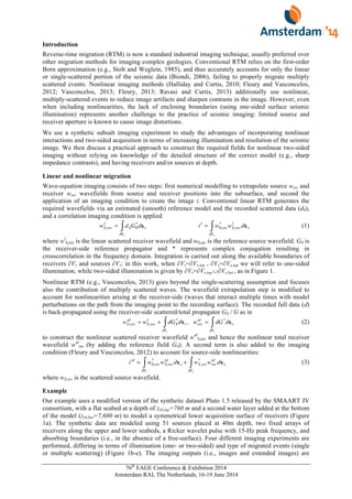
Figure 3 Extended images constructed via (a) direct modeling, (b) one-sided RTM, (c) one-sided nonlinear
RTM, (d) two-sided RTM, and (e) two-sided nonlinear RTM. Close-ups show focusing around zero-offset zero-
time for one-sided migration, while blue/red arrows identify up/downgoing reconstructed energy in the different
experiments.
responsible for the construction of some (not all) of the events: upgoing events are mainly constructed
in the causal part while downgoing events are in the acausal one. Multiple reflections, properly
handled via nonlinear imaging, provide additional contributions to some of the physical events given
by linear imaging and sometimes also correct their polarity; transmissions construct events that are
complementary to those from reflection data (e.g., transmission data construct upgoing waves in the
acausal part and downgoing waves in the causal part), improving the time symmetry in reconstructed
gathers.
Acknowledgements
The authors thank the Edinburgh Interferometry Project (EIP) sponsors (ConocoPhillips,
Schlumberger, Statoil, and Total) for supporting this research. We are thankful to James Rickett and
Dirk-Jan van Manen for insightful discussions and inputs. This work was performed while Matteo
Ravasi was an intern at Schlumberger Gould Research.
References
Biondi, B. [2006] 3D seismic imaging. SEG.
Broggini, F., Snieder, R., and Wapenaar, K. [2012] Focusing the wavefield inside an unknown 1D medium –
beyond seismic interferometry. Geophysics, 77, (5), A25-A28.
da Costa, C., Ravasi, M., Meles, G., and Curtis, A. [2014] Elastic autofocusing. 76th
EAGE Conference &
Exhibition Extended Abstracts.
Fleury, C. [2013] Increasing illumination and sensitivity of reverse-time migration with internal multiples.
Geophysical Prospection, 61, (5), 891-906.
Fleury, C. and Vasconcelos, I., [2012] Imaging condition for nonlinear scattering-based imaging: Estimate of
power loss in scattering. Geophysics, 77, (1), S1-S18.
Halliday, D., and Curtis, A. [2010] An interferometric theory of source-receiver scattering and imaging.
Geophysics, 75, SA95–SA103.
Ravasi, M. and Curtis, A. [2013] Nonlinear scattering based imaging in elastic media: theory, theorems and
imaging conditions. Geophysics, 78, (3).
Stolt, R. and Weglein, A. [1985] Migration and inversion of seismic data. Geophysics, 50, 2458-2472.
Vasconcelos, I. [2013] Source-receiver reverse-time imaging of dual-source, vector-acoustic seismic data.
Geophysics, 78, (2), WA147-WA158.
Vasconcelos, I., Sava, P., and Douma, H. [2010] Nonlinear extended images via image-domain interferometry.
Geophysics, 75, (6), SA105–SA115.
Wapenaar, K., Broggini, F., Slob, E., and Snieder, R. [2013] Three-Dimensional Single-Sided Marchenko
Inverse Scattering, Data-Driven Focusing, Green’s Function Retrieval, and Their Mutual Relations.
Physical Review Letters, 110, (8), 084301.](https://image.slidesharecdn.com/45770cdc-09fc-4979-80c8-2bed2c68d67d-151119205919-lva1-app6892/85/Ravasi_etal_EAGE2014-5-320.jpg)