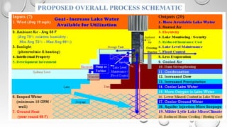
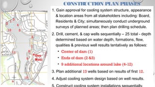
PROPOSED OVERALL PROCESS SCHEMATIC
Existing Water Cooling System
Graphic provided by D. Hall
Water Cooling Diagram
Graphic provided by D. Hall
Evaporation Reduction Projection
50,000,000+ GALLONS
Underground Temperature DifferentialUnderground Temperature Differential
Lake Area Wells Reported to Texas Water Development Board
It appears there is significant seepage
from Lytle into aquifers surrounding &
below lake. Seepage of water above a
set level can be accelerated for storage.
Also, appears aquifers extend deeper
than any of the wells reported thus far.
Proposed towers / tanks / waterfalls
seen from Northwest Shore
OVERLAY RENDERING OF PROPOSED EQUIPMENT
CONSTRUCTION PLAN PHASES
1. Gain approval for cooling system structure, appearance
& location areas from all stakeholders including: Board,
Residents & City; simultaneously conduct underground
surveys of planned areas; then plan drilling schedule.
2. Drill, cement, & cap wells sequentially – 25 total - depth
determined based on water depth, formations, flow,
qualities & previous well results tentatively as follows:
• Center of dam (1)
• Ends of dam (2 &3)
• 9 additional locations around lake (4-12)
3. Plan additional 13 wells based on results of first 12.
4. Adjust cooling system design based on well results.
1
3
2 4
6
7
10
11
12
*Dry
Well
5
8
9

WATER CONSERVATION PROPOSAL

  • 1.
  • 2.
    Existing Water CoolingSystem Graphic provided by D. Hall
  • 3.
    Water Cooling Diagram Graphicprovided by D. Hall
  • 4.
  • 5.
  • 6.
    Lake Area WellsReported to Texas Water Development Board It appears there is significant seepage from Lytle into aquifers surrounding & below lake. Seepage of water above a set level can be accelerated for storage. Also, appears aquifers extend deeper than any of the wells reported thus far.
  • 7.
    Proposed towers /tanks / waterfalls seen from Northwest Shore OVERLAY RENDERING OF PROPOSED EQUIPMENT
  • 8.
    CONSTRUCTION PLAN PHASES 1.Gain approval for cooling system structure, appearance & location areas from all stakeholders including: Board, Residents & City; simultaneously conduct underground surveys of planned areas; then plan drilling schedule. 2. Drill, cement, & cap wells sequentially – 25 total - depth determined based on water depth, formations, flow, qualities & previous well results tentatively as follows: • Center of dam (1) • Ends of dam (2 &3) • 9 additional locations around lake (4-12) 3. Plan additional 13 wells based on results of first 12. 4. Adjust cooling system design based on well results. 1 3 2 4 6 7 10 11 12 *Dry Well 5 8 9