This document is the project report for developing a polymer composite manhole cover using waste and recycled materials. It includes an acknowledgements section thanking the author's supervisor and project members. The abstract provides an overview of the study, which investigated manufacturing manhole covers using recycled polymeric waste materials like glass fibre and rubber particles, along with an epoxy resin matrix. The document outlines the experimental methods used, including materials, processing, and characterization tests. It presents results from tensile, impact, and bend tests and discusses the effects of adding different amounts of rubber particles and glass fibre on mechanical properties.
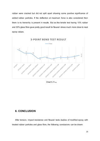
![27
CengizCelikbilek,G.A.C. K.,2004. Modificationof Epoxybya LiquidElastomerandSolidRubber
Particles. PoIymerBuIIetin, Volume51,pp.429-435.
CevdetKaynak,C.C.G. A.,2003. Use of silane couplingagentstoimprove epoxy–rubberinterface.
European PolymerJournal, Volume 39,pp.1125-1132.
E. Paul DeGarmo,J. T. B. R. A. K.,2003. MATERIALSANDPROCESSIN MANUFACTURING. 9thed.
s.l.:JohnWiley&Sons,Inc.
E. Sipahi-Saglam,C.K.G. A. M. Y. N. A.,2001. StudiesonEpoxyModifiedWithRecycledRubber.
PolymerEngineering And Science , Volume 41,pp. 514-521.
F.G. Smithl,E. D. A. T.,1995. Testingandevaluatingcommercial applicationsof new surface-treated
rubbertechnologyutilizingwaste tires. resources,conservation and recycling, Volume 15,pp.133-
144.
R. BAGHERI, M. A. W. R. A.P., 1997. Use of Surface ModifiedRecycledRubberParticlesfor
Tougheningof EpoxyPolymers. POLYMERENGINEERINGANDSCIENCE, Volume 37,pp.245-251.
SongAiteng,Y.Y., 1990. CTBN-toughenedepoxyresinseffectof curingmechanismonnetwork
structure of the rubberphase. ChineseJournalof PolymerScience, Volume 8,pp.183-187.
staff,P.,2015. Compositesdo a good cover-up job. [Online]
Available at:http://www.prw.com/subscriber/headlines2.html?id=6281
[Accessed25 04 2015].
STANDARD,B.,1994. Gully topsand manholetopsforvehicularand pedestrian areas - Design
requirements,typetesting,marking,quality control. Brussels:CEN.
Wait,C. F., 2010. The Reuse and Recycling of Glass Fibre Waste, Birmingham:s.n.](https://image.slidesharecdn.com/401e2ec0-4eb8-46d7-b212-f3937f5df114-150715110548-lva1-app6892/85/40135619-M-Sc-report-27-320.jpg)
![28
9. BIBLIOGRAPHY
B.J.P.Jansen,K.T. H. M. P. L., 1999. Preparationof thermosetrubberyepoxyparticlesasnovel
tougheningmodifiersforglassyepoxyresins. Polymer, Volume 40,pp.5601-5607.
BHADRA,A.,2010. MICROSTRUCTURE–MECHANICALPROPERTYRELATIONSHIPOFCRUMBRUBBER–
POLYURETHANEFOAMCOMPOSITES, Oklahoma:s.n.
CengizCelikbilek,G.A.C. K.,2004. Modificationof Epoxybya LiquidElastomerandSolidRubber
Particles. PoIymerBuIIetin, Volume51,pp.429-435.
CevdetKaynak,C.C.G. A.,2003. Use of silane couplingagentstoimprove epoxy–rubberinterface.
European PolymerJournal, Volume 39,pp.1125-1132.
E. Paul DeGarmo,J. T. B. R. A. K.,2003. MATERIALSANDPROCESSIN MANUFACTURING. 9thed.
s.l.:JohnWiley&Sons,Inc.
E. Sipahi-Saglam,C.K.G. A. M. Y. N. A.,2001. StudiesonEpoxyModifiedWithRecycledRubber.
PolymerEngineering And Science , Volume 41,pp. 514-521.
F.G. Smithl,E. D. A. T.,1995. Testingandevaluatingcommercial applicationsof new surface-treated
rubbertechnologyutilizingwaste tires. resources,conservation and recycling, Volume 15,pp.133-
144.
R. BAGHERI, M. A. W. R. A.P., 1997. Use of Surface ModifiedRecycledRubberParticlesfor
Tougheningof EpoxyPolymers. POLYMERENGINEERINGANDSCIENCE, Volume 37,pp.245-251.
SongAiteng,Y.Y., 1990. CTBN-toughenedepoxyresinseffectof curingmechanismonnetwork
structure of the rubberphase. ChineseJournalof PolymerScience, Volume 8,pp.183-187.
staff,P.,2015. Compositesdo a good cover-up job. [Online]
Available at:http://www.prw.com/subscriber/headlines2.html?id=6281
[Accessed25 04 2015].
STANDARD,B.,1994. Gully topsand manholetops forvehicularand pedestrian areas - Design
requirements,typetesting,marking,quality control. Brussels:CEN.
Wait,C. F., 2010. The Reuse and Recycling of Glass Fibre Waste, Birmingham:s.n.](https://image.slidesharecdn.com/401e2ec0-4eb8-46d7-b212-f3937f5df114-150715110548-lva1-app6892/85/40135619-M-Sc-report-28-320.jpg)