This document provides technical specifications for various oil and gas drilling equipment made from AISI 4130 steel pipe and fittings by Seawave Offshore, including:
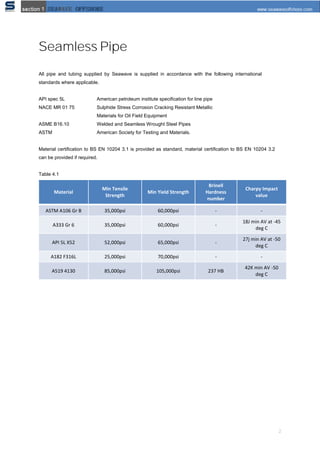
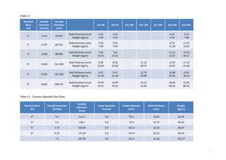
- Seamless pipe in various schedules and sizes that meet international standards for material properties and testing.
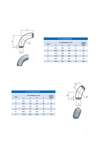
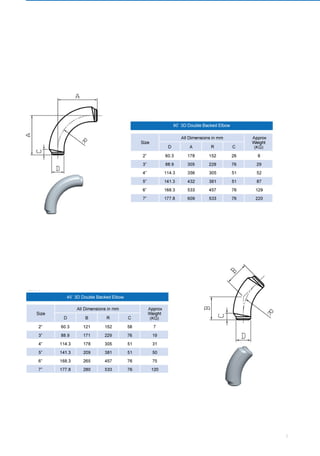
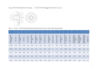
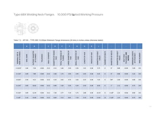
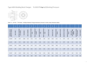
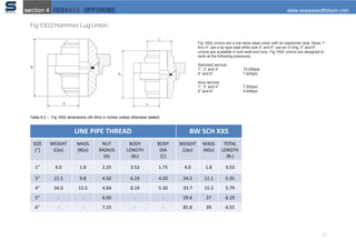
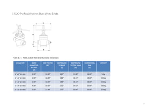
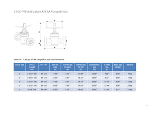
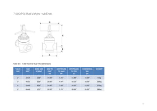
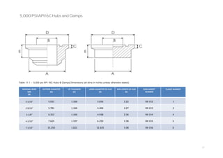
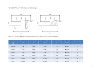
- High pressure manifold fittings in carbon manganese and alloy steels rated for maximum working pressures of 5,000-15,000 psi.
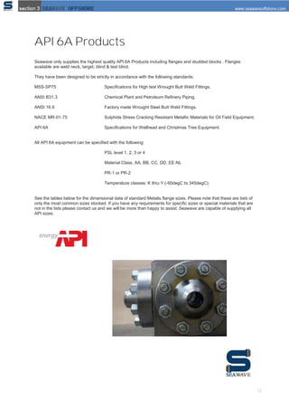
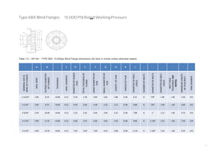
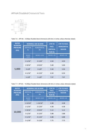
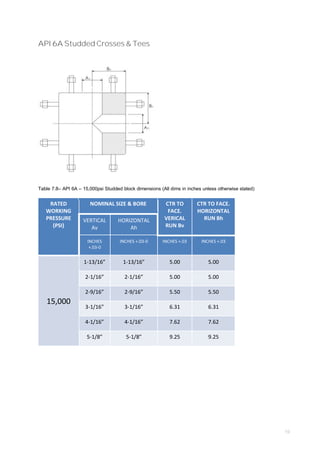
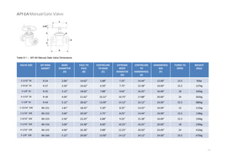
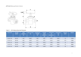
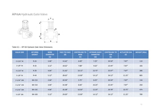
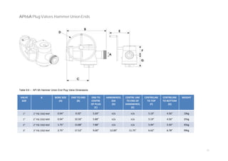
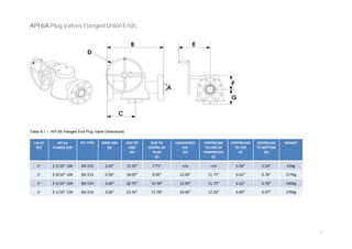
- API 6A certified products like flanges, studded blocks, and valves available in various pressure classes and temperature ratings.