The document provides instructions for setting up and using a wireless customer premises router (CPE). It includes:
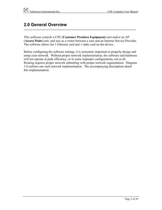
1) An overview of the CPE and its capabilities, including routing traffic between a user network and internet service provider.
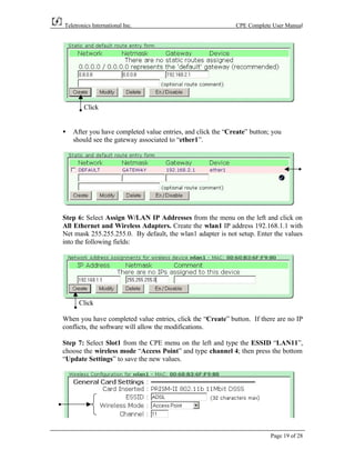
2) Details on proper network implementation, including using the CPE as a router between wired and wireless networks with different IP ranges.
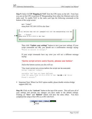
3) Instructions for accessing and navigating the CPE's browser-based user interface to configure settings like IP addresses, default gateways, and wireless settings.
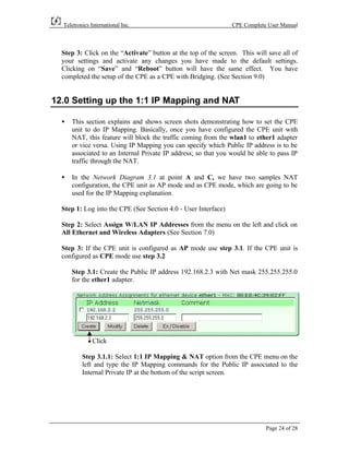
4) Step-by-step directions for basic CPE configuration options, including setting the CPE up as a router with network address translation between its Ethernet and wireless interfaces.


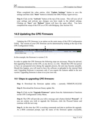
![Teletronics International Inc. CPE Complete User Manual
followed by the IP address of the CPE and then followed by the name of the binary
firmware. The syntax for the firmware update utility is,
firmupl102 ip-address firmware.bin
ie: firmupl102 192.168.1.1 cpe-218.bin
Step 6: The firmware update will update the CPE. Once completed, you will see the
following message.
CPE Firmware upgrade utility version 1.02-win32
Windows port - Aug 21, 2001. BETA
MD5 Checksum for this file: 6cefdf7df87bee06884b5af845e71438
Connected: CPE is currently running firmware version 2.13-pr2
Sending firmware, please wait....
[##################################################] - 8028160 (7840K)
Firmware has been sent.
Finished. Waiting for server to verify the firmware....
Success! The CPE will now reboot using the new firmware.
Step 7: You will need to wait for 2 minutes, while the CPE is checking the firmware
and rebooting. After rebooting, you may connect to the CPE using the regular
protocol (See Section 4.0 User Interface). You can now configure the settings using
the web browser, as described.
Page 28 of 28](https://image.slidesharecdn.com/cprumv218-090930183231-phpapp01/85/versa-router-teletronics-29-320.jpg)