This paper explores the application of Cat Swarm Optimization (CSO) in optimizing the Selective Harmonic Elimination (SHE) algorithm for Current Source Inverters (CSI) to minimize Total Harmonic Distortion (THD). The study highlights the effectiveness of CSO in tuning switching parameters, improving the output quality of CSIs by eliminating low-order harmonics in the inverter's waveform. Simulations conducted in MATLAB demonstrate significant improvements in harmonic elimination, validating the proposed methodology.
![International Journal of Power Electronics and Drive System (IJPEDS)
Vol. 6, No. 4, December 2015, pp. 888~896
ISSN: 2088-8694 888
Journal homepage: http://iaesjournal.com/online/index.php/IJPEDS
Utlization Cat Swarm Optimization Algorithm for Selected
Harmonic Elemination in Current Source Inverter
Hamed Hosseinnia, Morteza Farsadi
Department of Electrical and Computer Engineering, Urmia University, Urmia, Iran
Article Info ABSTRACT
Article history:
Received Jul 15, 2015
Revised Oct 19, 2015
Accepted Nov 5, 2015
The voltage source inverter (VSI) and Current source inverter (CSI) are two
types of traditional power inverter topologies.In this paper selective
harmonic elimination (SHE) Algorithm was impelemented to CSI and results
has been investigated. Cat swarm (CSO) optimization is a new meta-heuristic
algorithm which has been used in order to tuning switching parameters in
optimized value.Objective fuction is reduction of total harmonic
distortion(THD) in inverters output currents.All of simulation has been
carried out in Matlab/Software.
Keyword:
Current source inverter
Meta-heurestic algorithm
Switching parameters tuning
Total harmonic distortion
Copyright © 2015 Institute of Advanced Engineering and Science.
All rights reserved.
Corresponding Author:
Hamed Hosseinnia,
Departement of Electrical and Computer Engineering,
Urmia University,
Urmia, Iran.
Email: Hamed.Hosseinnia@gmail.com
1. INTRODUCTION
There are two types of traditional power inverter topologies, Vlotage source inverter (VSI) and
Current source inverter (CSI).The voltage source inverter produces a specified three-phase PWM voltage
waveform for the load while the current source inverter outputs a specified three-phase PWM current
waveform. Figure 1 show the CSI .the CSI is able to inject power to the grid without any additional dc/dc
converter, but low harmonic is major problem in this kind of inverter and reduction of these harmonic is
object of several researchers work.In additional these harmonics limited applications of CSI in frequency
domain.CSI derives in the megawatt range are widely used in the industry[1],[2].The conventional three
phase current source inverter has the defect of introducing increased lower order harmonics in the output
current which give rise in to losses and torque pulsation in the machine.Elimination of low order harmonic is
so important in CSIs to avoid possible resonance between the input/output filter capacitance and input/output
circuit inductance.
In this paper current source inverter has been investigated and Selected Harmonic Elimination
(SHE) switching algorithems has been impelemented. Several types of switching introduced in literature are
introduced like: Trapezoidal PWM switching, Selective Harmonic Elimination (SHE) and Space vector
Modulation (SVM) [3].](https://image.slidesharecdn.com/2319oct1526sep8603hamededit-171217161855/85/Utlization-Cat-Swarm-Optimization-Algorithm-for-Selected-Harmonic-Elemination-in-Current-Source-Inverter-1-320.jpg)
![IJPEDS ISSN: 2088-8694
Utlization Cat Swarm Optimization (CSO) Algorithm for Selected Harmonic .... (Hamed Hosseinnia)
889
Id
S1 S3 S5
S4 S6 S2
A
B
C
Iw
P
N
Figure 1. Conventional Current Source Inverter (CSI)
Selective harmonic elimination (SHE) is a method to eliminate a number of low-order harmonic in
the inverter PWM current. It is a well-known method for generating PWM signals that can eliminate low
order harmonic in specified voltage or current waveform [4]. One of easy way to have qualified output
waveform is that eliminate some low harmonic.if number of pulses per half cycle is Np; the number of angles
that implemented to harmonic elimination is achived (1):
(1)
For example with five pulses per half cycle, there are two independent angles, 1 and 2 .the two
switching angles provide two degrees of freedom which can be used to either eliminate two harmonic in
current or voltage waveform.in this paper current source inverter has been utilized [5]. The inverter PWM
current can generally be expressed (2):
1
( ) sin(nwt)n
n
i wt a
(2)
/2
0
4
a ( )sin( ) ( )n i wt nwt d wt
The furrier coefficient an can be found from (3)
1 1 2 2
1 1 2 2
cos( ) cos( ( )) cos( ) cos( ( )) ...
3 3
cos(n ) cos( ( ) cos( ), j
4 3 6
cos( ) cos( ( )) cos( ) cos( ( )) ...
3 3
cos( ) cos(n( )) cos( ), j even
3 6
j j
dc
n
j j
n n n n
n n odd
I
a
n
n n n n
n n
(3)
To eliminate j harmonics, j equations can be formulated by setting an =0.
1
2
Np
j
](https://image.slidesharecdn.com/2319oct1526sep8603hamededit-171217161855/85/Utlization-Cat-Swarm-Optimization-Algorithm-for-Selected-Harmonic-Elemination-in-Current-Source-Inverter-2-320.jpg)
![ ISSN: 2088-8694
IJPEDS Vol. 6, No. 4, December 2015 : 888 – 896
890
2. CAT SWARM OPTIMIZATION (CSO) ALGORITHM
Cat swarm algorithm (CSO) is based on the behavior of cats with exceptionally vigorous vitality of
curiosity toward moving objects and possecing good hunting skills. Chu and Tsai proposed a new
optimization algorithm that imitates the natural behavior of cats. Even though cats spend most of their time
resting, they always remain alert and move very slowly. These two characterictics of resting with slow
movement and chasing with high speed represented by seeking and tracing, respectively. In CSO, these two
modes of operations are mathematically modeled for solving complex optimization problems. These modes
are termed the "seeking and tracing" modes. A combination of these two modes allowes CSO has better
performance.
Seeking mode has four essential factors: seeking memory pool (SMP), seeking range of the selected
dimention (SRD), counts of dimention to change (CDC), and the self position consideration (SPC). Once a
cats goes into tracing mode , it moves accourding to its own velocities for every dimensions. Every cat has its
own position composed of D dimentionse, velocities for each dimension, a fitness value representing the
accommodation of the cat to the benchmark functiona and a flag to identify wether the cat is in seeking mode
or tracing mode. These two modes are dedicated to join with each other by mixture ratio (MR). The final
position would be the best position of one of the cats [6].
The computational procedure of the proposed optimization algorithm in the form of flowchart is
shown in Figure 2. Which is now described in detail?
I. Randomly initialize the initial set of cats of size Npop ,where each cat is of dimention D , Xi={xi1 ,xi2
,…,xiD }
II. Initialize the velocity of each cat, i.e., the velocity of cat I in the D-dimentional space as Vi= {Vi1 ,Vi2
,…,ViD }.
III. Evaluate the fitness of each cat and keep the position of the cat that has the higest fitness value.
IV. According to parameter mixing ratio (MR), cats are randomly distributed to seeking and tracing modes.
V. If cat k is in seeking mode then
a) Create SMP-1 copies of the kth cat and retain the present position as one copy;
b) For each copy according to CDC, randomly select the dimension to be mutated.
c) For the dimension selected for each copy, randomly add or subtract the SRD percent of the present
value;
d) Calculate the fitness value of all copies and replace orginal cat k with the copy having best fitness
value.
VI. If cat k is in tracing mode ,then
a) Update the velocity for every dimension of the kth cat :
1
( );j j j j
k k kv w v r GB x
b) Check if the velocities are in the range of maximum velocity; in case the new velocity is over range,
set it equal to the maximum limit;
c) Update the position for every dimension of the kth cat:
1 1
x j j j
k k kx v
d) Constrain the position of the cat so that it doesn’t exceed the limits of interest;
e) Evaluate the fitness of each cat and store the position of the cat that has the best fitness value and
compare the previous global best value with the current best value accordingly;
f) Check if the maximux pre-specified number of iterations is reached, which is used as the termination
critiation, if YES terminate the program, else go to step.
Because the importance of minimizing THD value, the objective function is defined as below (4)
[7]:
(4)
0
. .
simt
M t THD dt ](https://image.slidesharecdn.com/2319oct1526sep8603hamededit-171217161855/85/Utlization-Cat-Swarm-Optimization-Algorithm-for-Selected-Harmonic-Elemination-in-Current-Source-Inverter-3-320.jpg)
![IJPEDS ISSN: 2088-8694
Utlization Cat Swarm Optimization (CSO) Algorithm for Selected Harmonic .... (Hamed Hosseinnia)
891
START
Create N Cats
Initialize the position,
velocities and the flag of
every cat
Evaluate the cats according to the fitness
function and keep the position of the cat,
which has the best fitness value
Cat K is in the seeking mode?
Apply Cat K into tracing
mode process
Apply Cat K into Seeking
mode Process
Re-Peek Number of Cats and set them into tracing mode
according to MR, and set the others into seeking mode
NOYes
END
Figure 2. Cat Swarm Optimization (CSO) Flowchart
3. TUNING SIMULATION PARAMETERS
In this paper CSO algorithm implement to tuning switching parameters to minimize objective
function. Objective function (OF) is minimization of total harmonic distortion (THD). For example for
reduction THD in waveform with Np =5, and to eliminate 5th and 7th harmonics, the following two equation
can be drive (5);
1 1 2 2
1 1 2 2
3
cos(5 ) cos(5( )) cos(5 ) cos(5( )) 0
3 3 2
3
cos(7 ) cos(7( )) cos(7 ) cos(7( )) 0
3 3 2
(5)
In SHE algorithm minimized value for THD is obtioned with tuning angles in best value. In Figure 3
number of signals for eliminating two harmonic and its manner has been shown. In Figure 4 proposed way to
generating pulses for switches has been illustrated [8],[9].](https://image.slidesharecdn.com/2319oct1526sep8603hamededit-171217161855/85/Utlization-Cat-Swarm-Optimization-Algorithm-for-Selected-Harmonic-Elemination-in-Current-Source-Inverter-4-320.jpg)
![ ISSN: 2088-8694
IJPEDS Vol. 6, No. 4, December 2015 : 888 – 896
892
S1
S2
S3 S4 S5
π
Θ1 Θ2 π/6
π/3-Θ2
π/3-Θ1
π/2
Figure 3. Switching signals for 5 th and 7 th Harmonic Elimination
OR
Gate
And
Gate
S1
S2
NOT
And
Gate
S3
S4
NOT
S5
Pulse Generation
Figure 4. Proposed Method for pulse generating in Selective Harmonic Elimination
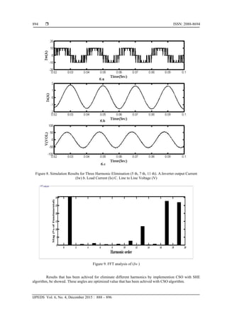
3.1. Simulation Results
Simulation was conducted with the configuration shown in Figure 5. The simulation parameters are:
Idc=6A, C=40µF, L=10mH, R=10Ω. The simulation results with CSO are shown in Figure 6. This Figure
included of Line to Line voltage and Load Current and output current of Inverter (Iw ). In additional FFT
analysis of Iw has been shown in Figure 7. This figure proving CSO algorithm operation in 5th
and 7th
harmonic elimination with SHE switching method [10],[11]. For additional example to prove CSO algorithm
operation this metod done in three harmonic elimination (5th
,7th
,11th
) and results have been illustrated in
Figure 8 and Figure 9.](https://image.slidesharecdn.com/2319oct1526sep8603hamededit-171217161855/85/Utlization-Cat-Swarm-Optimization-Algorithm-for-Selected-Harmonic-Elemination-in-Current-Source-Inverter-5-320.jpg)

![IJPEDS ISSN: 2088-8694
Utlization Cat Swarm Optimization (CSO) Algorithm for Selected Harmonic .... (Hamed Hosseinnia)
895
Table 1. Optimized Value for switching angle in SHE Algorithm
Harmonic to be
Eliminated
Switching Angles
1 2 3
5 17.15 - -
7 20.56 - -
11 23.75 - -
13 25.6 - -
5,7 7.85 14.2 -
5,11 13 19.5 -
5,13 14.75 22 -
7,11 15.21 19.45 -
7,13 16.23 21
5,7,11 2.42 5.8 21.43
7,11,13 9.6 11.72 24.13
5,11,13 7.62 10.82 23.4
4. CONCLUSION
As simulation result showed, by tuning selected angles in optimized value, THD of the output
current is better then arbitariry chosen values and quality of CSI output is improved.this verifies effectiveness
of the Selected Harmonic Elimination (SHE) with Cat Swarm Optimization (CSO). CSO can be applied to
any problem where optimization is required.therefore it can be applied in many usage in power electronic and
power marketing.the comparation of the results in this paper with similar work in other literature show CSO
algorithm befit for optimization issues [12]-[15].
REFERENCES
[1] Mitsuyuki H, et al. "A New Current Source GTO Inverter with Sinusoidal Output Voltage and Current", IEEE
Transactions on Industrial Electronics, vol. 21, pp. 1192-1198, 1985.
[2] DEEPAC Kumar, Zakir Husain, "Estimation of Harmonics in Three-Phase and Six-Phase Load Circuits", IJPEDS,
vol/issue: 5(2), pp. 142-152, 2014.
[3] Kwack S., et al., "An Integrated Current Source Inverter with Reactive and Harmonic Power Compensators", IEEE
Tractions on Power Electronics, vol/issue: 24(2), 2009.
[4] AM. Trzynadlowski, N. Patriciu, F. Blaabjerg, JK. Pedersen, “A hybrid, Current-source/voltage-source power
inverter circuit”, IEEE Trans. Power Electron, vol/issue: 16(6), pp. 866–871, 2001.
[5] Jose R., Espinoza, Geza Joos, Johan I Guzman, Luis AMoran, Rolando P. Burgos, “Selective Harmonic
Elimination and current/voltage control in current/voltage-source topologies: A unified approach”, IEEE
Transactions on industry electronics, 2001.
[6] Kusumalatha Y., Obulesh Y., "Harmonics Mitigation of Industrial Motor Drives with Active Power Filters in
Cement Plant-A Case Study", IJPEDS, vol/issue: 2(1), pp. 1-8, 2012.
[7] Durgasukumar G., MK. Pathak, “THD Reduction Performance of Multi-Level Inverter fed Induction Motor Drive”,
presented at the India International Conference on Power Electronics (IICPE), 2011.
[8] Orouskhani M., Mansouri M., Teshnehlab M., “Average-Inertia weighted Cat swarm optimization”, LNCS, Berlin
Heidelberg: Springer-Verlag, pp. 321– 328, 2011.
[9] José R. Espinoza, et al, "Selective Harmonic Elimination and Current/Voltage Control in Current/Voltage-Source
Topologies: A Unified Approach", IEEE Transactions on Industrial Electronics, vol/issue: 48(1), 2001.
[10] Abdul Rahiman Beig, Ranganathan V., "A Novel CSI-Fed Induction Motor Drive", IEEE Transactions on Power
Electronics, vol/issue: 21(4), pp. 45-49, 2006.
[11] Delli Colli V., Cancellieve P., Marignetti F., R. Di Stefano, "Influence of Voltage and Current Source Inverters on
Low-power Induction motors", IEEE Proc-Electrical Power Appl., vol/issue: 152(5), pp. 1311-1320, 2005.
[12] Hamed, Hosseinnia, et al, "Simple Boost Control Method Optimized withGenetic Algorithm for Z-Source
Inverter", JEPECS, vol/issue: 1(1), pp. 32-36, 2013.
[13] Karshenas H., Kojori H., Dewan S., “Generalised technique of selective harmonic elimination and current control
in Current Source Inverter/Converter”, IEEE transactions on Power Electronics, vol/issue: 10(5), pp. 566-573,
1995.
[14] Vázquez N., López H., Hernández C., Rodríguez E., Orosco R., Arau J., "A Grid Connected Current Source
Inverter", IEEE International conference on Clean Electrical Power, pp. 439 442, 2009.
[15] SC. Chu, PW. Tsai, JS. Pan, “Cat swarm optimization”, in PRICAI 2006: Trends in Artificial Intelligence,
Springer, pp. 854–858, 2006.](https://image.slidesharecdn.com/2319oct1526sep8603hamededit-171217161855/85/Utlization-Cat-Swarm-Optimization-Algorithm-for-Selected-Harmonic-Elemination-in-Current-Source-Inverter-8-320.jpg)