Inventors and entrepreneurs have vocations fueled by passion. Many would have done it for free or as a hobby if it hadn’t become a profession. Mark Rosenzweig is a natural creator, driven by his passion. This fuel has led Mark to develop his ideas into viable products and innovations that he has been patenting since 2003. From an innovative filter sensor and indicator for vacuum cleaners to a basket for deep fryer and methods of cooking food products to a compact cyclonic bagless vacuum cleaner. Sometimes independently and often as part of creative teams, Mark has patented just under one hundred innovative inventions between 2003 and 2017.
In electrical discharge machining (EDM), Copper
and Graphite are commonly used as electrode (tool) materials.
EDM process is based on thermoelectric energy between an
electrode and workpiece. In this paper, the effect of electrode wear
rate (EWR) in 202 stainless steel is observed. Copper Electrode is
used as tool material and SS-202 is used as workpiece. Copper
electrode possess high structural integrity, so it can produce very
fine surface finishes, even without special polishing circuits.
This document describes a waveguide composition that allows for excitation of two perpendicular polarizations using a simplified design. It includes a dielectric supporting material with metallic patterns for first and second feed conductors. A first excitation device supplied by the first feed conductor excites a first polarization, while a second excitation device supplied by the second feed conductor excites a second polarization. The design aims to provide a lower cost dual-polarization waveguide composition compared to previous designs that used multiple separate components. It includes embodiments with integrated waveguide parts and arrangements that are symmetrical about a vertical axis to excite the two polarizations.
The patent document describes an electrical splice connector. It includes a body, conductor contacting wedges that are movably mounted on the body, and anti-reverse clips connected to the body that contact the wedges. The anti-reverse clips include tabs that limit backward movement of the wedges relative to the body and prevent the wedges from becoming inadvertently disconnected from the body during use. The document provides detailed drawings and descriptions of the body, wedges, and anti-reverse clips that make up the electrical splice connector.
73 keith f. mello - 6796854 - automatic electrical wedge connectorMello_Patent_Registry
This patent is for an automatic electrical wedge connector. It describes a connector comprising a shell and a wedge. The shell defines a wedge receiving passage, and the wedge is shaped to wedge into the passage to hold a conductor. The shell has first and second portions with different flexure stiffnesses, generating different clamping forces on the wedge. This allows the connector to securely hold conductors of varying sizes using the same connector.
100 sadanand v. deshpande - 7344983 - clustered surface preparation for sil...Mello_Patent_Registry
Sadanand V. Deshpande, Ying Li, Kevin E. Mello, Renee T. Mo, Wesley C. Natzle, Kirk D. Peterson, Robert J. Purtell - Clustered Surface Preparation for Silicide and Metal Contacts
38 keith f. mello - 5888104 - paint penetrating ground clamp for painted ra...Mello_Patent_Registry
The document describes a paint penetrating ground clamp for electrically grounding painted raised floor pedestals. It consists of an upper clamp part, lower clamp part, and U-bolt. The upper clamp part has barbs or sharp edges formed by piercing into its pedestal contact surface at an acute angle. This creates projections that penetrate the pedestal's paint when the clamp is tightened, establishing electrical contact with the pedestal through the paint without requiring paint removal.
This document provides details of a metal rectifier assembly, including:
- A block of insulating material with holes containing stacks of rectifier elements.
- A sheet of flexible insulating material folded to form panels contacting the block, with metallic connections interfacing the stacks.
- A sheet metal container pressing the insulating material into contact with the stacks.
- Improved embodiments provide a "circuit card" with tags connected to metallic connections to simplify assembly and reduce incorrect connections.
This document describes improvements to ion traps in cathode-ray tubes. Specifically, it describes a cathode-ray tube design where the axis of the tubular anode adjacent to the cathode is not coaxial with but intersects the common axis of preceding electrodes. This allows the electrode system and overall tube length to be shorter compared to traditional designs where the anode has a bent coaxial section, reducing material and manufacturing costs while providing more space for getters. The design achieves satisfactory ion trapping through deflection of electrons and ions by a magnetic field near the intersection of the anode and preceding electrode axes.
This document describes improvements to ion traps in cathode-ray tubes. Specifically, it describes a cathode-ray tube design where the axis of the tubular anode adjacent to the cathode is not coaxial with but intersects the common axis of preceding electrodes. This allows the electrode system and overall tube length to be shorter compared to traditional designs where the anode has a bent coaxial section, reducing material needs and providing more space for getters. The design achieves satisfactory ion trapping through deflecting electrons and ions with a magnetic field at the point where the anode axis intersects the common axis of preceding electrodes.
This document describes improvements to ion traps in cathode-ray tubes. Specifically, it describes a cathode-ray tube design where the axis of the tubular anode adjacent to the cathode is not coaxial with but intersects the common axis of preceding electrodes. This allows the ion trap to operate satisfactorily while avoiding disadvantages of prior designs that required the anode to have a coaxial part. The new design allows for a shorter overall electrode system length compared to prior bent anode designs.
This document describes improvements to ion traps in cathode-ray tubes. Specifically, it describes a cathode-ray tube design where the axis of the tubular anode adjacent to the cathode is not coaxial but intersects the common axis of preceding electrodes. This allows the electrode system and anode construction to be shorter and simpler while still effectively trapping ions, providing advantages for manufacturing. The design deflects electrons toward the anode axis and screen center using a magnetic field, while ions continue toward the anode wall.
This patent describes improvements to capacitor design for high current applications. It discloses a capacitor that includes an expandable part on the housing. When a fault occurs inside the housing, the expandable part expands and causes the housing to extend in length and contact an external interrupter. The external interrupter includes an electrode and sensing circuit. The sensing circuit detects contact between the housing and electrode, and sends a signal to disconnect the capacitor from the external circuit. This design allows for fault detection without an internal fault interrupter, making the capacitor simpler and less costly to manufacture.
The effects of heat input and interpass temperature on the microstructure of ...Mark Keeler
This thesis examines the effects of heat input and interpass temperature on the microstructure of duplex stainless steel during welding. Two sets of 5 butt welds were made with heat inputs of 1.0 KJ/mm and 1.5 KJ/mm. The interpass temperature was varied from 150°C to 350°C between welds. Micrographic examination found that intermetallic precipitates formed at a heat input of 1.5 KJ/mm and interpass temperature of 350°C, but not at 1.0 KJ/mm. Lower interpass temperatures of 200°C also showed signs of microstructural effects. The results indicate that excessive heat input and interpass temperatures can alter the microstructure
AMP Unit.3 advanced manufacturing techniques for material processing(badebhau...Er. Bade Bhausaheb
This document provides information on several advanced material processing techniques:
1. Shape Tube Electrolytic Machining (STEM) which uses a shaped cathode tool to electrolytically machine small holes.
2. Electrolytic In-process Dressing (ELID) which uses electrolysis to dress grinding wheels during precision grinding.
3. Electrochemical Grinding (ECG) which utilizes a negatively charged abrasive grinding wheel, electrolyte, and positively charged workpiece to grind materials electrochemically.
1) The document describes an electronic switching unit comprising two tubes (Bla and Bib) that can alternately conduct or not conduct based on the control grid voltage of the first tube (Bla).
2) The switching unit uses voltage dividers to regenerate the amplitude of the applied switching potential and output nominal and inverted values of the potential at its terminals.
3) By applying multiple switching units in series and connecting their reference potentials, only one voltage source is needed to power the circuit.
This document describes an electronic switching unit patent from 1957. The switching unit contains two tubes (which can be a single double-triode tube) that are controlled such that one tube is conductive while the other is non-conductive. Voltage dividers are used to regenerate the switching voltages without needing additional elements. The switching unit is suitable for use in code converters and binary computer systems to invert switching potentials with a small amplitude.
This document describes a patent for improvements in forming hermetic seals between metallic parts without heat. It involves arranging indium between the metallic surfaces and applying pressure to cause the indium to diffuse into each surface, forming an airtight seal. The indium cold-welds easily and provides a vacuum-tight bond at room temperature between metals like copper. The seal can withstand baking up to 600°C without deterioration.
This document describes a patent for improvements in forming hermetic seals between metallic parts without heat. It involves arranging indium between the surfaces to be sealed and applying pressure to cause the indium to diffuse into each metal surface, forming an airtight bond. The indium cold-welds easily and provides a vacuum-tight seal at room temperature without oxidation. The method allows sealing parts where heat could cause unwanted oxidation or deformation.
This document describes a patent for improvements in forming hermetic seals between metallic parts without heat. It involves arranging indium between the metallic surfaces and applying pressure to cause the indium to diffuse into each surface, forming an airtight seal. The indium cold-welds easily and provides a vacuum-tight bond at room temperature between metals like copper. The seal can withstand baking up to 600 degrees C without deterioration.
This document describes a patent for improvements in forming hermetic seals between metallic parts without heat. It involves arranging indium between the metallic surfaces and applying pressure to cause the indium to diffuse into each surface, forming an airtight seal. The indium cold-welds easily and provides a vacuum-tight bond at room temperature between metals like copper. The seal can withstand baking up to 600°C without deterioration.
International Journal of Engineering Research and Applications (IJERA) is an open access online peer reviewed international journal that publishes research and review articles in the fields of Computer Science, Neural Networks, Electrical Engineering, Software Engineering, Information Technology, Mechanical Engineering, Chemical Engineering, Plastic Engineering, Food Technology, Textile Engineering, Nano Technology & science, Power Electronics, Electronics & Communication Engineering, Computational mathematics, Image processing, Civil Engineering, Structural Engineering, Environmental Engineering, VLSI Testing & Low Power VLSI Design etc.
49 keith f. mello - 6186799 - compression grounding connector for rail and ...Mello_Patent_Registry
The document describes a compression grounding connector for connecting a conductor to a rail or structural steel member. The connector comprises a first frame member and at least one second piercing insert member. The piercing insert has protrusions that pierce into the rail member when the connector is compressed, providing both mechanical and electrical connection. The connector can be used to ground signaling systems or buildings.
This document describes a slip ring arrangement for electrically connecting testing equipment to rotating equipment like motors and generators. It involves applying a flexible tape with conductive strips and insulating layers onto the rotating shaft. This allows temporary thermistors or other sensors to be connected for measuring temperature or other variables during field service and testing, without requiring a custom-fitted slip ring assembly. The tape can be wrapped around shafts of varying sizes and the conductive strips form slip rings that brushes connect to, bringing sensor signals to measuring devices. This overcomes issues with conventional slip ring assemblies and allows faster, easier temporary testing of rotating equipment.
This document contains past exam questions from the Anna University course EE 2355 Design of Electrical Machines. It includes both short 2-mark questions and longer 16-mark questions on topics like specific electric loading, armature reaction reduction methods, transformer design, DC machine design dimensions, induction motor dimensions, and synchronous machine performance parameters like short circuit ratio. The questions cover the design aspects of transformers, DC machines, induction motors, and synchronous machines.
Advanced techniques for material processing PDF by badebhau4@gmail,comEr. Bade Bhausaheb
This document provides an overview of several advanced material processing techniques:
1. Shape Tube Electrolytic Machining (STEM) uses an acid electrolyte and cathodic tool to dissolve and remove metal from a workpiece, allowing cylindrical holes to be machined.
2. Electrolytic in-process dressing (ELID) uses electrolysis to dress grinding wheels during precision grinding, improving wheel performance.
3. Electrochemical grinding (ECG) utilizes a negatively charged abrasive grinding wheel, electrolyte, and positively charged workpiece to grind materials electrochemically like ECM.
Inventors and entrepreneurs have vocations fueled by passion. Many would have done it for free or as a hobby if it hadn’t become a profession. Mark Rosenzweig is a natural creator, driven by his passion. This fuel has led Mark to develop his ideas into viable products and innovations that he has been patenting since 2003. From an innovative filter sensor and indicator for vacuum cleaners to a basket for deep fryer and methods of cooking food products to a compact cyclonic bagless vacuum cleaner. Sometimes independently and often as part of creative teams, Mark has patented just under one hundred innovative inventions between 2003 and 2017.
Building Your Employer Brand with Social MediaLuanWise
Presented at The Global HR Summit, 6th June 2024
In this keynote, Luan Wise will provide invaluable insights to elevate your employer brand on social media platforms including LinkedIn, Facebook, Instagram, X (formerly Twitter) and TikTok. You'll learn how compelling content can authentically showcase your company culture, values, and employee experiences to support your talent acquisition and retention objectives. Additionally, you'll understand the power of employee advocacy to amplify reach and engagement – helping to position your organization as an employer of choice in today's competitive talent landscape.
Unveiling the Dynamic Personalities, Key Dates, and Horoscope Insights: Gemin...my Pandit
Explore the fascinating world of the Gemini Zodiac Sign. Discover the unique personality traits, key dates, and horoscope insights of Gemini individuals. Learn how their sociable, communicative nature and boundless curiosity make them the dynamic explorers of the zodiac. Dive into the duality of the Gemini sign and understand their intellectual and adventurous spirit.
B2B payments are rapidly changing. Find out the 5 key questions you need to be asking yourself to be sure you are mastering B2B payments today. Learn more at www.BlueSnap.com.
Brian Fitzsimmons on the Business Strategy and Content Flywheel of Barstool S...Neil Horowitz
On episode 272 of the Digital and Social Media Sports Podcast, Neil chatted with Brian Fitzsimmons, Director of Licensing and Business Development for Barstool Sports.
What follows is a collection of snippets from the podcast. To hear the full interview and more, check out the podcast on all podcast platforms and at www.dsmsports.net
How are Lilac French Bulldogs Beauty Charming the World and Capturing Hearts....Lacey Max
“After being the most listed dog breed in the United States for 31
years in a row, the Labrador Retriever has dropped to second place
in the American Kennel Club's annual survey of the country's most
popular canines. The French Bulldog is the new top dog in the
United States as of 2022. The stylish puppy has ascended the
rankings in rapid time despite having health concerns and limited
color choices.”
How to Implement a Real Estate CRM SoftwareSalesTown
To implement a CRM for real estate, set clear goals, choose a CRM with key real estate features, and customize it to your needs. Migrate your data, train your team, and use automation to save time. Monitor performance, ensure data security, and use the CRM to enhance marketing. Regularly check its effectiveness to improve your business.
How to Implement a Strategy: Transform Your Strategy with BSC Designer's Comp...Aleksey Savkin
The Strategy Implementation System offers a structured approach to translating stakeholder needs into actionable strategies using high-level and low-level scorecards. It involves stakeholder analysis, strategy decomposition, adoption of strategic frameworks like Balanced Scorecard or OKR, and alignment of goals, initiatives, and KPIs.
Key Components:
- Stakeholder Analysis
- Strategy Decomposition
- Adoption of Business Frameworks
- Goal Setting
- Initiatives and Action Plans
- KPIs and Performance Metrics
- Learning and Adaptation
- Alignment and Cascading of Scorecards
Benefits:
- Systematic strategy formulation and execution.
- Framework flexibility and automation.
- Enhanced alignment and strategic focus across the organization.
[To download this presentation, visit:
https://www.oeconsulting.com.sg/training-presentations]
This presentation is a curated compilation of PowerPoint diagrams and templates designed to illustrate 20 different digital transformation frameworks and models. These frameworks are based on recent industry trends and best practices, ensuring that the content remains relevant and up-to-date.
Key highlights include Microsoft's Digital Transformation Framework, which focuses on driving innovation and efficiency, and McKinsey's Ten Guiding Principles, which provide strategic insights for successful digital transformation. Additionally, Forrester's framework emphasizes enhancing customer experiences and modernizing IT infrastructure, while IDC's MaturityScape helps assess and develop organizational digital maturity. MIT's framework explores cutting-edge strategies for achieving digital success.
These materials are perfect for enhancing your business or classroom presentations, offering visual aids to supplement your insights. Please note that while comprehensive, these slides are intended as supplementary resources and may not be complete for standalone instructional purposes.
Frameworks/Models included:
Microsoft’s Digital Transformation Framework
McKinsey’s Ten Guiding Principles of Digital Transformation
Forrester’s Digital Transformation Framework
IDC’s Digital Transformation MaturityScape
MIT’s Digital Transformation Framework
Gartner’s Digital Transformation Framework
Accenture’s Digital Strategy & Enterprise Frameworks
Deloitte’s Digital Industrial Transformation Framework
Capgemini’s Digital Transformation Framework
PwC’s Digital Transformation Framework
Cisco’s Digital Transformation Framework
Cognizant’s Digital Transformation Framework
DXC Technology’s Digital Transformation Framework
The BCG Strategy Palette
McKinsey’s Digital Transformation Framework
Digital Transformation Compass
Four Levels of Digital Maturity
Design Thinking Framework
Business Model Canvas
Customer Journey Map
Structural Design Process: Step-by-Step Guide for BuildingsChandresh Chudasama
The structural design process is explained: Follow our step-by-step guide to understand building design intricacies and ensure structural integrity. Learn how to build wonderful buildings with the help of our detailed information. Learn how to create structures with durability and reliability and also gain insights on ways of managing structures.
At Techbox Square, in Singapore, we're not just creative web designers and developers, we're the driving force behind your brand identity. Contact us today.
Storytelling is an incredibly valuable tool to share data and information. To get the most impact from stories there are a number of key ingredients. These are based on science and human nature. Using these elements in a story you can deliver information impactfully, ensure action and drive change.
Easily Verify Compliance and Security with Binance KYCAny kyc Account
Use our simple KYC verification guide to make sure your Binance account is safe and compliant. Discover the fundamentals, appreciate the significance of KYC, and trade on one of the biggest cryptocurrency exchanges with confidence.
Digital Marketing with a Focus on Sustainabilitysssourabhsharma
Digital Marketing best practices including influencer marketing, content creators, and omnichannel marketing for Sustainable Brands at the Sustainable Cosmetics Summit 2024 in New York
Part 2 Deep Dive: Navigating the 2024 Slowdownjeffkluth1
Introduction
The global retail industry has weathered numerous storms, with the financial crisis of 2008 serving as a poignant reminder of the sector's resilience and adaptability. However, as we navigate the complex landscape of 2024, retailers face a unique set of challenges that demand innovative strategies and a fundamental shift in mindset. This white paper contrasts the impact of the 2008 recession on the retail sector with the current headwinds retailers are grappling with, while offering a comprehensive roadmap for success in this new paradigm.
Best practices for project execution and deliveryCLIVE MINCHIN
A select set of project management best practices to keep your project on-track, on-cost and aligned to scope. Many firms have don't have the necessary skills, diligence, methods and oversight of their projects; this leads to slippage, higher costs and longer timeframes. Often firms have a history of projects that simply failed to move the needle. These best practices will help your firm avoid these pitfalls but they require fortitude to apply.
1. US 20060042933A1
(19) United States
(12) Patent Application Publication (10) Pub. No.: US2006/0042933 A1
Rosenzweig et al. (43) Pub. Date: Mar. 2, 2006
(54) ELECTROPLATING APPARATUS AND (52) U.S. Cl. ............................................ 204/242; 204/232
METHOD FOR MAKING AN
ELECTROPLATING ANODE ASSEMBLY
(76) Inventors: MarkAlan Rosenzweig, Hamilton, OH 5s s 7 ABSTRACT
(US); Robert George Zimmerman (57)
JR., Morrow, OH (US); John D. Evans
SR., Springfield, OH (US)
Correspondence Address: Apparatus for electroplating a workpiece includes an unas
Thompson Hine LLP Sembled electroplating anode assembly having weldable
2000 Courthouse Plaza NE first and Second structural anode members. The first struc
P.O. BOX 8801 tural anode member includes a positioning slot. The Second
Dayton, OH 45401-8801 (US) Structural anode member includes a positioning tab dispos
(21) Appl. No.: 10/926,739 able in the positioning slot. A method for making an elec
troplating anode assembly includes obtaining an electroplat
(22) Filed: Aug. 26, 2004 ing-anode-assembly first Structural anode member having a
positioning slot and obtaining an electroplating-anode-as
Publication Classification Sembly Second structural anode member having a position
(51) Int. Cl. ing tab. The method also includes locating the positioning
C25B I5/00 (2006.01) tab in the positioning slot and welding together the first and
C25B 9/00 (2006.01) Second Structural anode members.
1O
36
22 5O
44
18
40 5O
38 41A. . .
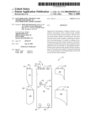
2. Patent Application Publication Mar. 2, 2006 Sheet 1 of 2 US 2006/0042933 A1
1 O
36
22 5O
-4?,
18
4O 50
38 1A. . .
28
F.G. 1
4. US 2006/0042933 A1
ELECTROPLATING APPARATUS AND METHOD
FOR MAKING AN ELECTROPLATING ANODE
ASSEMBLY
BACKGROUND OF THE INVENTION
0001. The present invention relates generally to applying
a coating on a workpiece, and more particularly to an
electroplating apparatus and to a method for making an
electroplating anode assembly.
0002. It is known to coat turbine airfoils, such as turbine
airfoils of an aircraft engine, with platinum aluminide dif
fusion coatings for protection against high temperature
oxidation and corrosion. To develop the platinum aluminide
coating, the parts are firstplatinum electroplated. It isknown
to use the electrolyte Pt(NH), HPO, for platinum electro
plating turbine airfoils.
0003. In a known electroplating method, a cathode rack
Supports Several turbine airfoils and an anode rack Supports
Several electroplating anode assemblies. The turbine airfoils
and the electroplating anode assemblies are in contact with
the Pt(NH), HPO electrolyte, and a rectifierisemployed to
apply a Voltage between the cathode and anode racks for
platinum electroplating of the turbine airfoils. Each electro
plating anode assembly has TIG (Tungsten-Inert-Gas) butt
welded together first, Second and third structural anode
titanium (or titanium alloy) sheet-metal plate members. A
conforming platinum-clad niobium anode mesh (i.e., an
anode mesh having a shape which Substantially conforms to
the shape of a Surface portion of a turbine airfoil) is
Supported by two of the first, Second, and third structural
anode plate members. The anode mesh is electrochemically
active during electroplating while the Sheet-metal plate
members build up an anodic film and passivate during the
electroplating proceSS. Difficulties in precisely positioning
the plate members for welding often result in plate position
ing errors which lead to undesirable coating thickness varia
tions, blistered platinum deposits, no platinum deposits due
to Short circuits, and damage to anode assemblies and
turbine airfoils when the cathode and anode racks are
brought into position for electroplating.
0004 Still, scientists and engineers continue to seek
improved electroplating apparatus and improved methods
for making an electroplating anode assembly.
BRIEF DESCRIPTION OF THE INVENTION
0005. A first expression of an embodiment of the inven
tion is apparatus for electroplating a workpiece. The appa
ratus includes an unassembled electroplating anode assem
bly. The unassembled electroplating anode assembly
includes weldable first and Second structural anode mem
bers. The first Structural anode member includes a position
ing slot. The Second structural anode member includes a
positioning tab disposable in the positioning slot.
0006 A first method of the invention is for making an
electroplating anode assembly and includes Several StepS.
One Step includes obtaining an electroplating-anode-assem
bly first Structural anode member having a positioning slot.
Another Step includes obtaining an electroplating-anode
assembly Second structural anode member having a posi
tioning tab. An additional Step includes locating the posi
tioning tab in the positioning slot. A further Step includes
welding together the first and Second Structural anode mem
bers.
Mar. 2, 2006
0007. In one example of the first method and the first
expression of an embodiment of the invention, there is
included a third structural anode member, wherein the first
Structural anode member has a first Set of two positioning
through slotsand hasa SecondSetoftwopositioningthrough
Slots, wherein the Second structural anode member has two
positioning tabS matingly disposed in the two positioning
slots of the first set, wherein the third structural anode
member has two positioning tabs matingly disposed in the
two positioningslots ofthe Second Set, wherein the slots and
tabs are adapted to allow the Second structural anode mem
ber tobe disposed in only the positioningslotsofthe firstSet
and to allow the third structural anode member to be
disposed in only the positioningslots ofthe Second Set. This
allows, in one implementation, Shorterelectroplating-anode
assembly fabrication times andprecise positioning for Weld
ing together the first, Second and third structural anode
members.
BRIEF DESCRIPTION OF THE DRAWING
0008. The accompanying drawing illustrates an embodi
ment of the invention wherein:
0009 FIG. 1 is a schematic diagram of five anode
Structural members of an unassembled electroplating anode
assembly; and
0010 FIG. 2 is a schematic diagram of an assembled
electroplating assembly having the five anode structural
members of FIG. 1 and having two attached active-anode
meshes each facing a Surface portion of a different turbine
airfoil.
DETAILED DESCRIPTION OF THE
INVENTION
0011 Referring now to the drawing, FIGS. 1-2 disclose
an embodiment of the invention. A first expression of the
embodiment of FIGS. 1-2 is an apparatus 10 for electro
plating a workpiece 12. The apparatus 10 includes an
unassembled electroplating anode assembly 14. The elec
troplating anode assembly 14 includes weldable first and
second structural anode members 16 and 18. By “structural”
is meant Substantially rigid. The first Structural anode mem
ber 16 includes a positioning Slot 20, and the Second
Structural anode member 18 includes a positioning tab 22
disposable in the positioningslot 20. It is noted that describ
ing the apparatus as having aparticular component (Such as
an electroplating anode assembly) means that the apparatus
has at least one particular component (Such as at least one
electroplatinganode assembly). Likewise,describingacom
ponent as having a particular feature (such as a positioning
Slot) means that the component has at least one particular
feature (Such as at least one positioning slot).
0012. A second expression of the embodiment of FIGS.
1-2 is an apparatuS 10 forelectroplating a workpiece 12. The
apparatus 10 includes an electroplating anode assembly 14.
The electroplating anode assembly 14 includes first and
Second structural anode members 16 and 18. The first
Structural anode member 16 includes a positioning slot 20.
The second structural anode member 18 includes a position
ing tab 22 disposed in the positioning slot 20. The first and
Second structural anode members 16 and 18 are welded
together.
5. US 2006/0042933 A1
0013 In one construction ofthe second expression ofthe
embodiment of FIGS. 1-2, the positioning slot 20 is a
through slot. In the same or a different construction, the first
and second structural anode members 16 and 18 are Sub
Stantially-rigid plate members.
0.014. In one enablement of the second expression of the
embodiment of FIGS. 1-2, the electroplating anode assem
bly 14 also includes an active-anode mesh 24 Supported by
at least one of the first and Second structural anode members
16 and 18. An active-anode mesh is an anode mesh which
remains electrochemically active during electroplating of
the workpiece. In one variation, the workpiece 12 includes
a workpiece Surface portion 26 having a shape, and the
activate anode mesh 24 has a shape which Substantially
conforms to the Shape of the workpiece Surface portion 26.
In the same or a different variation, the first and Second
structural anode members 16 and 18 are first and second
Structural inactive-anode members. A structural inactive
anode member is astructural anode memberwhich builds up
an anodic film and electrochemically passivates during
electroplating of the workpiece.
0015. Athird expression ofthe embodiment of FIGS. 1-2
is an apparatuS 10 for electroplating a workpiece 12. The
apparatus 10 includes an unassembled electroplating anode
assembly 14. The unassembled electroplating anode assem
bly 14 includes weldable first, second and third structural
anode members 16, 18 and 28. The first structural anode
member 16 includes positioningslots20,30,32 and34. The
Second and third structural anode members 18 and 28 each
include two positioningtabs(tabs22 and 36 for member 18
and tabs 38 and 40 for member 28).
0016. The positioning slots 20, 30, 32 and 34 and posi
tioning tabs22,36,38 and 40) are adapted to allow the two
positioning tabs 22 and 36 of the Second Structural anode
member 18 to be disposed in only a particular pair of
positioningslots 20 and 30 and to allow the two positioning
tabs 38 and 40 of the third structural anode member 28 to be
disposed in only a separate particular pair of positioning
slots 32 and 34.
0017. A fourth expression of the embodiment of FIGS.
1-2 is an apparatuS 10 forelectroplating a workpiece 12. The
apparatus 10 includes an electroplating anode assembly 14.
The electroplating anode assembly 14 includes first, Second
and third structural anode members 16, 18 and 28. The
Second and third structural anode members 18 and 28 each
include two positioningtabs(tabs22 and 36 for member 18
and tabs38and40formember28).Thefirststructuralanode
member 16 includes a firstset 42 oftwo positioningslots 20
and 30 and a second set 44 of two positioning slots 32 and
34. The two positioning tabs 22 and 36 of the second
Structural anode member 18 are matingly disposed one each
in the two positioning slots20 and 30 ofthe first set 42. The
two positioning tabs 38 and 40 of the third structural anode
member 28 are matingly disposed one each in the two
positioning slots 32 and 34 of the second set 44. The first,
Second and thirdstructuralanode members 16, 18 and28 are
welded together.
0.018. In one construction of the fourth expression of the
embodiment of FIGS. 1-2, the distance between the two
positioningslots20and30ofthe first set 42 is different from
the distance between the two positioning slots 32 and 34 of
the Second Set44. In the same or a different construction, the
Mar. 2, 2006
length of one of the two positioning slots 20 and 30 of the
first set 42 is different from the length of any of the two
positioning slots 32 and 34 of the second set 44. In one
variation, the length of any of the two positioning slots 20
and 30 of the first set 42 is different from the length ofany
of the two positioning slots 32 and 34 of the second set 44.
In the same or a different construction, the length of one of
the two positioning slots 20 and 30 of the first set 42 is
different from the length of the other of the two positioning
slots 20 and 30 of the first set 42, and the length of one of
the two positioning slots 32 and 34 of the second set 44 is
different from the length of the other of the two positioning
slots 32 and 34 of the second set 44. In examples of one or
more or allofSuch constructions, astructural anode member
can only be assembled in a unique pair of positioning slots
of another Structural anode member. In one variation a
Structural anode member can only have one orientation in a
pair of positioning slots which are non-through slots.
0019. In one enablement of the fourth expression of the
embodiment of FIGS. 1-2, the workpiece 12 is a turbine
airfoil. In the same or a different enablement, the electro
plating anode assembly 14 also includes an active-anode
mesh 24 Supported by at least two of the first, Second and
third structural anode members 16, 18 and28. In one choice
of materials, the first, Second and third structural anode
members 16, 18 and 28 comprise titanium, the active-anode
mesh 24 consists essentially of platinum-clad niobium, and
the turbine airfoil comprises a nickel-based Superalloy. In
one variation, the Structural anode members are machine cut
by watedjet or laser.
0020. A first method of the invention is for making an
electroplatinganode assembly 14 and includesSeveral StepS.
One Step includes obtaining an electroplating-anode-assem
bly first structural anode member 16 having a positioning
Slot 20. Another Step includes obtaining an electroplating
anode-assembly Second structural anode member 18 having
a positioning tab. 22. An additional Step includes disposing
the positioning tab 22 in the positioning slot 20. A further
Step includes weldingtogether the first andSecond structural
anode members 16 and 18.
0021. Asecond method ofthe invention is for making an
electroplating anode assembly 14 for electroplating a work
piece 12 and includes steps a) through f). Step a) includes
obtaining an electroplating-anode-assembly first structural
anode member 16 having a first Set 42 of two positioning
slots 20 and 30 and a second set 44 of positioning slots 32
and 34. Step b) includes obtaining an electroplating-anode
assembly Second structural anode member 18 having two
positioning tabs 22 and 36 matingly disposable one each in
the two positioning slots20 and 30 ofthe first set 42 but not
the Second Set 44. Step c) includes obtaining an electroplat
ing-anode-assembly third structural anode member 28 hav
ing two positioning tabs 38 and 40 matingly disposable one
each in the two positioningslots 32 and34 ofthe second set
44 but not the first set 42. Step d) includes matingly
disposing the two positioning tabs 22 and 36 of the Second
structural anode member 18 in the two positioning slots 20
and30ofthe firstset42.Stepe)includesmatingly disposing
the two positioning tabs 38 and 40 of the third structural
anode member 28 in the two positioning slots 32 and 34 of
the Second Set44. Step f) includes welding together the first,
Second and third structural anode members 16, 18 and 28.
6. US 2006/0042933 A1
0022. In one implementation of the second method, dur
ing step d), a particular one of the two positioning tabs 22
and 36 ofthe second structural anode member 18 is dispos
able in only a particular one of the two positioning slots 20
and 30 ofthe firstSet42, and,duringstep e),aparticularone
of the two positioning tabs 38 and 40 of the third structural
anode member 28 is disposable in only a particular one of
the two positioning slots 32 and 34 of the second set 44.
0023. In one enablement of the second method, the
positioning slots 20, 30, 32 and 34 of the first and second
Sets 42 and 44 are through slots. In one variation, the
positioning tabs 22, 36, 38 and 40 of the second and third
structural anode members 18 and28 have free ends, andstep
f) includes welding the free ends of the matingly-disposed
positioning tabs 22, 36, 38 and 40 of the second and third
structural anode members 18 and 28 to the first structural
anode member 16.
0024. In one application of the second method, the work
piece 12 is a turbine airfoil. In one variation, the Second
method also includes the Step of obtaining an active-anode
mesh 24 having a shape Substantially conforming to the
shape of a Surface portion of the turbine airfoil and the Step
ofSecuringthe active-anode mesh 24to the Second and third
structural anode members 18 and 28. In one modification,
the active-anode mesh 24 is spot welded to the Second and
third structural anode members 18 and 28.
0.025. It is noted that the previously-described construc
tions, enablements, variations, etc. of any of the methods
and expressions ofthe embodiment of FIGS. 1-2 are equally
applicable to any one or more or all of the other of the
methods and expressions of the embodiment of FIGS. 1-2.
In one extension ofany one or more or all ofthe previously
described methods andexpressions ofan embodiment of the
invention, the electroplating anode assembly 14 includes
two additional structural anode members 46 and 48 having
positioning tabs 50. In this extension, the first structural
anode member 16 has additional positioning slots 52, the
positioning tabs 50 of the two additional structural anode
members46 and48 are disposable/disposedin the additional
positioning slots 52, the two additional Structural anode
members 46 and 48 are weldable/welded to the first struc
turalanode member 16, and an additionalactive-anode mesh
54 is securable/secured to the two additional structural
anode members 46 and 48 for electroplating a surface
portion ofan additional workpiece 56. In one utilization, the
electroplating anode assembly 14 is copied a plurality of
times with all of the electroplating anode assemblies Sup
ported by an anode rack (not shown) Such as a titanium (or
titanium alloy) anode rack. In one example, the first struc
tural anode member 16 has attachment holes 58 for bolt
attachment to the anode rack. A cathode rack (not shown),
Such as a StainleSSSteel cathode rack, Supports a multiplicity
of workpieces Such as turbine airfoils. An electrolyte, Such
as Pt(NH), HPO, is in contact with the workpieces and the
active anode meshes (such as 125DCX screen available
from Vincent Metals Corporation of Rhode Island), and a
rectifier applies a dc (direct current) Voltage across the
cathode and anode racks to electroplate the workpieces. In
one experiment, electroplating anode assemblies for elec
troplating 16 turbine airfoils were fabricated within 12 hours
using the principles of the invention compared to a fabrica
tion time of up to 40 hours using conventional electroplat
ing-anode-assembly techniques.
Mar. 2, 2006
0026. While the present invention has been illustrated by
a description of Several methods and expressions of an
embodiment, it is not the intention of the applicants to
restrict or limit the Spirit and Scope of the appended claims
to Such detail. Numerous other variations, changes, and
Substitutions will occur to those skilled in the art without
departing from the Scope of the invention.
1.Apparatus for electroplatinga workpiece comprising an
unassembledelectroplating anode assembly including Weld
able first and Second structural anode members, wherein the
firststructural anode member includes a positioningslot and
wherein the Second structural anode member includes a
positioning tab disposable in the positioning slot.
2.Apparatusfor electroplatinga workpiece comprising an
electroplating anode assembly including first and Second
Structural anode members, wherein the first Structural anode
member includes a positioning slot, wherein the Second
Structural anode member includes a positioningtab disposed
in the positioning slot, and wherein the first and Second
Structural anode members are welded together.
3. The apparatus ofclaim 2, wherein the positioning slot
is a through slot.
4. The apparatus of claim 2, wherein the first and Second
Structural anode members are Substantially-rigid plate mem
bers.
5. The apparatus of claim 2, wherein the electroplating
anode assembly also includes an active-anode mesh Sup
portedby at least one ofthe first andSecondstructural anode
members.
6. The apparatus of claim 5, wherein the workpiece
includes a workpiece Surface portion having a shape and
wherein the active-anode mesh has a shape which Substan
tially conforms to the shape of the workpiece Surface
portion.
7. The apparatus of claim 5, wherein the first and second
Structural anode members are first and Second structural
inactive-anode members.
8.Apparatusfor electroplatinga workpiece comprising an
unassembledelectroplating anode assembly including Weld
able first, Second and third structural anode members,
wherein the firstStructural anode member includesposition
ing slots and wherein the Second and third Structural anode
memberseach include two positioning tabs, and wherein the
positioning Slots and positioning tabs are adapted to allow
the two positioning tabs of the Second structural anode
member to be disposed in only a particular pair ofposition
ing Slots and to allow the two positioning tabs of the third
Structural anode member to be disposed in only a Separate
particular pair of positioning slots.
9.Apparatus for electroplatinga workpiece comprising an
electroplating anode assembly including first, Second and
third Structural anode members, wherein the Second and
thirdstructuralanode memberseach include two positioning
tabs, wherein the first structural anode member includes a
first Set of two positioning slots and a Second Set of two
positioning slots, wherein the two positioning tabs of the
Second Structural anode member are matingly disposed one
each in the two positioning slots ofthe first Set, wherein the
two positioning tabs of the third structural anode member
are matingly disposed one each in the two positioning slots
of the Second Set, and wherein the first, Second and third
Structural anode members are welded together.
7. US 2006/0042933 A1
10. The apparatus of claim 9, wherein the distance
between the two positioning slots of the first set is different
from the distance between the two positioning slots of the
Second Set.
11. The apparatus ofclaim 9, wherein the length ofone of
the two positioning slots ofthe first set is different from the
length of any of the two positioning slots of the Second Set.
12. The apparatus of claim 11, wherein the length of any
of the two positioning slots of the first set is different from
the length of any of the two positioning Slots of the Second
Set.
13. The apparatus ofclaim 9, wherein the length ofone of
the two positioning slots ofthe first set is different from the
length ofthe otherofthe two positioningslots ofthe firstSet,
and wherein the length ofone of the two positioning slots of
the second set is different from the length ofthe other ofthe
two positioning slots of the Second Set.
14. The apparatus ofclaim 9, wherein the workpiece is a
turbine airfoil.
15. The apparatus ofclaim 14, wherein the electroplating
anode assembly also includes an active-anode mesh Sup
ported by at least two ofthe first,second and third structural
anode members, wherein the first, Second and third struc
tural anode members comprise titanium and wherein the
active-anode mesh consistsessentially ofplatinum-clad nio
bium.
16. A method for making an electroplating anode assem
bly comprising the Steps of:
a) obtaining an electroplating-anode-assembly first struc
tural anode member having a positioning Slot;
b) obtaining an electroplating-anode-assembly Second
Structural anode member having a positioning tab,
c) disposing the positioning tab in the positioning slot;
and
d) welding together the first and Second structural anode
members.
17. A method for making an electroplating anode assem
bly for electroplating a workpiece comprising the Steps of:
a) obtaining an electroplating-anode-assembly first struc
turalanode memberhavinga firstSetoftwo positioning
slots and a Second Set of positioning slots,
Mar. 2, 2006
b) obtaining an electroplating-anode-assembly Second
Structural anode member having two positioning tabs
matingly disposable one each in the two positioning
slots of the first set but not the second set;
c) obtainingan electroplating-anode-assembly thirdstruc
tural anode member having two positioning tabS mat
ingly disposable one each in the two positioning slots
of the second set but not the first set;
d) matingly disposing the two positioning tabs of the
Second structural anode member in the two positioning
slots of the first set;
e) matingly disposingthe two positioning tabsofthe third
Structural anode member in the two positioningslots of
the Second Set, and
f) welding together the first, Second and third structural
anode members.
18. The method of claim 17, wherein, during step d), a
particular one of the two positioning tabs of the Second
Structural anode member is disposable in only a particular
one ofthe two positioningslots ofthe firstSet, and wherein,
duringStepe), a particular one ofthe two positioningtabsof
the third structural anode member is disposable in only a
particular one of the two positioning slots of the Second Set.
19.The method ofclaim 17, wherein the positioningslots
of the first and second sets are through slots, wherein the
positioning tabs of the Second and third structural anode
members have free ends, and wherein step f) includes
welding the free ends of the matingly-disposed positioning
tabs of the second and third structural anode members to the
first Structural anode member.
20. The method of claim 19, wherein the workpiece is a
turbine airfoil, and also including the Step of obtaining an
active-anode mesh having a shape Substantially conforming
to the shape ofa surface portion ofthe turbine airfoil and the
Step of Securing the active-anode mesh to the Second and
third structural anode members.