Downloaded 132 times


![Results The cost model is based on a life-cycle approach
including all capitalised costs. The main up-scaling
Subtask A: Reference wind turbine and cost model parameter is typically the rotor diameter. The cost
As reference wind turbine an NREL 5 MW model - was model is basically formulated as function of this
used (see [1]) and improved. An overall framework for design parameter using an up-scaling factor with an
an optimal design of wind turbines was formulated, up-scaling exponent (typically 3) and a time-dependent
taking up-scaling and cost modelling into account [2] technology improvement factor.
and [3]. The approach is based on a life-cycle analysis
including all the expected costs and benefits through- Subtask B: Integral design approach methodology
out the lifetime of the wind turbine (wind farm). UpWind addresses the full life-cycle of the large-scale
wind turbines of the future, including the technical and
The cost model was developed for wind turbine up- commercial aspects. However, non-technical disciplines
scaling up to 20 MW. These wind turbines are expect- do not use any kind of model that is compatible with
ed to have a rotor diameter of approximately 250m the technical disciplines. There is a strong need for
and a hub height of 153m. A theoretical framework for new design paradigms that are able to account for both
a risk-based optimal design of large wind turbines was technical and non-technical disciplines within the same
formulated. Three types of formulation were made: 1) framework so that manufacturing, transport, installa-
a risk / reliability-based formulation, 2) a determinis- tion and O&M procedures become design parameters
tic, code-based formulation and 3) a crude determin- rather than constraints. A new design approach was
istic formulation. These formulations are described in proposed in UpWind. This approach is based on the
[2] and [3]. principles of systems engineering and features ele-
ments of Multi-disciplinary Design Optimisation (MDO),
In the third formulation (crude, deterministic), generic Knowledge Based Engineering (KBE) and Mono-discipli-
cost models are given as a function of the design nary Computational Analysis Methods (MCAM).
parameters using basic up-scaling laws adjusted for
technology improvement effects. There, the optimal The approach requires knowledge on the design pro-
design is the one which minimises the levelised cesses of the wind turbine and their subsystems to be
production costs. The main design parameters are: the captured and written down. The wind turbine techno-
rotor diameter, the hub height, the tip speed and where logies currently applied are in this approach, as well as
the wind turbines are placed in relation to one another those being studied and developed within the UpWind
in wind farms. In a more detailed approach, the cross- project. The captured knowledge is analysed and trans-
sectional dimensions (such as the geometry of the lated into knowledge applications through KBE. These
blade or the tower), the O&M strategy, or more refined applications address the following areas of the design:
input parameters can be included. External design
parameters are fixed regarding the size of the wind farm
(in terms of MW capacity and / or the geographical area
covered by the wind farm), the wind climate including
the terrain (mean wind speed and turbulence), wave and
current climate (offshore), water depth, soil conditions
and distance from land (or nearest harbour).
Design limits and solutions for very large wind turbines 23](https://image.slidesharecdn.com/upwindreport-121016072243-phpapp01/75/Upwind-Design-limits-and-solutions-for-very-large-wind-turbines-25-2048.jpg)
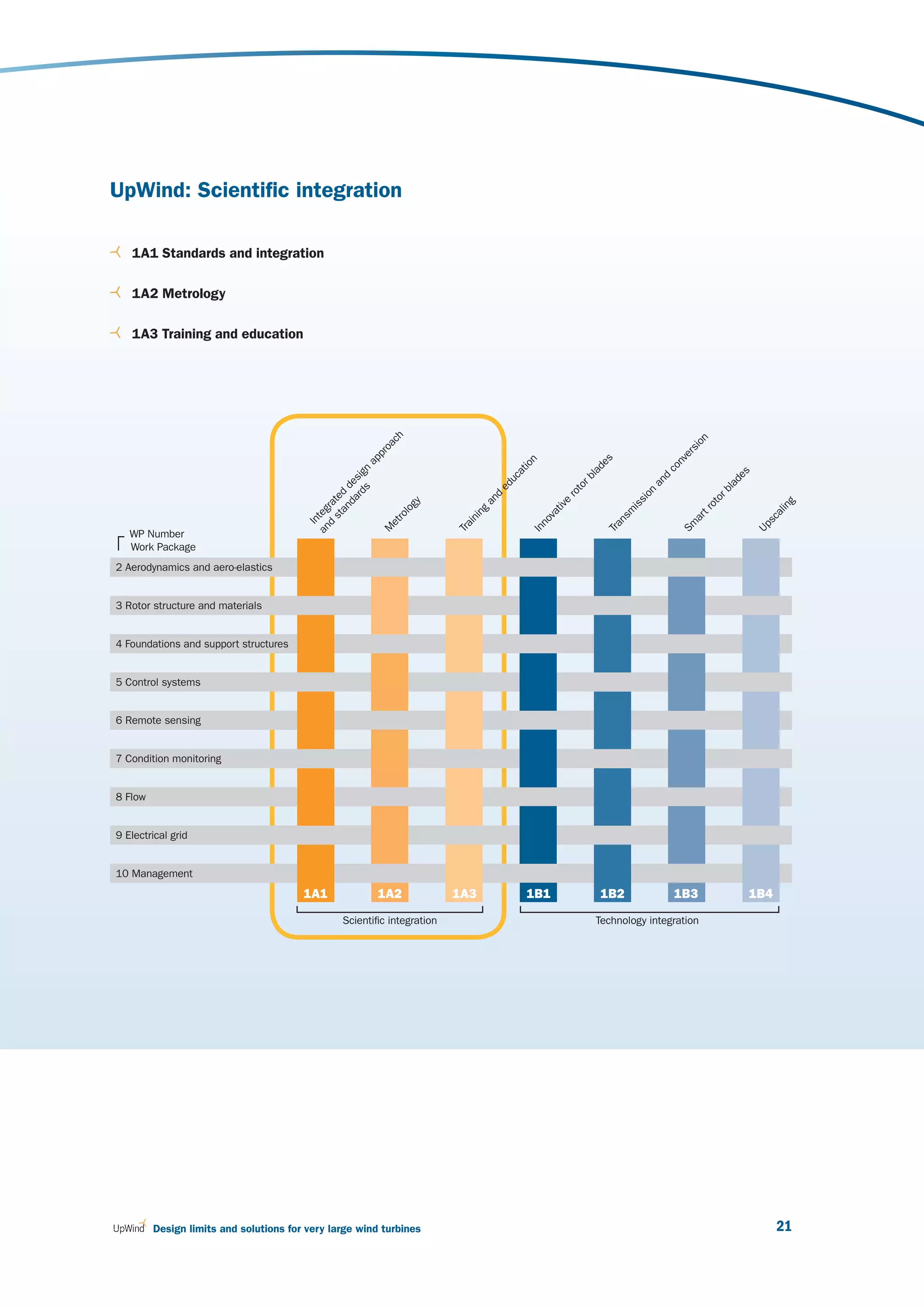
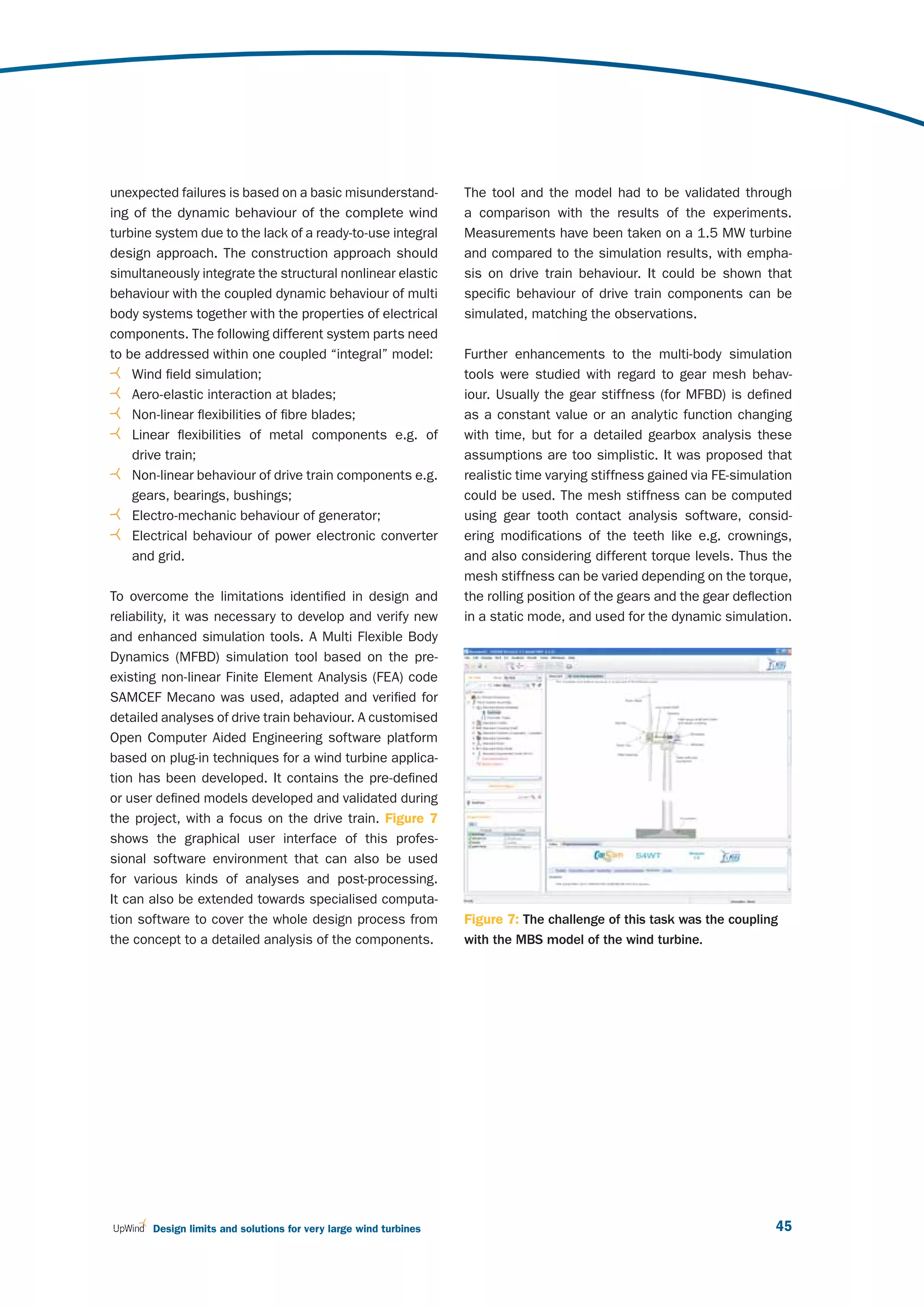
![2 UpWind: Scientific integration
The development of a parametric Multi Model This set of automated tools allows new wind turbine
Generator (MMG) for existing and new wind turbine concepts to be designed. Furthermore, the tools are
concepts. interconnected within what is known as a “Design and
Automation of the prepared models and aerody- Engineering Engine” (DEE) [4, 5, 6]. This framework
namic and structural analysis of the wind turbine enables the software tools to communicate through
components. agents or functions and provides a loosely coupled
Automation of the prepared models and aero-elastic demand-driven structure for the DEE. Within the frame-
analysis of wind turbine components. work, each tool is considered an engineering service
Automation of the prepared models and cost ana- providing functionality to the framework.
lysis of wind turbine components including material,
manufacturing, transport and installation.
Standardisation of a communication framework
between the different disciplines.
Work package 1
External conditions
Economic parameters
Analysis
Wind turbine within Wind turbine
design data WP1 performance
Conversion Conversion
PROJECT INTERNET SITE
Other work packages
Wind turbine Analysis Wind turbine
design data in other performance
WP
Figure 1 : The design and engineering engine
24 March 2011](https://image.slidesharecdn.com/upwindreport-121016072243-phpapp01/75/Upwind-Design-limits-and-solutions-for-very-large-wind-turbines-26-2048.jpg)
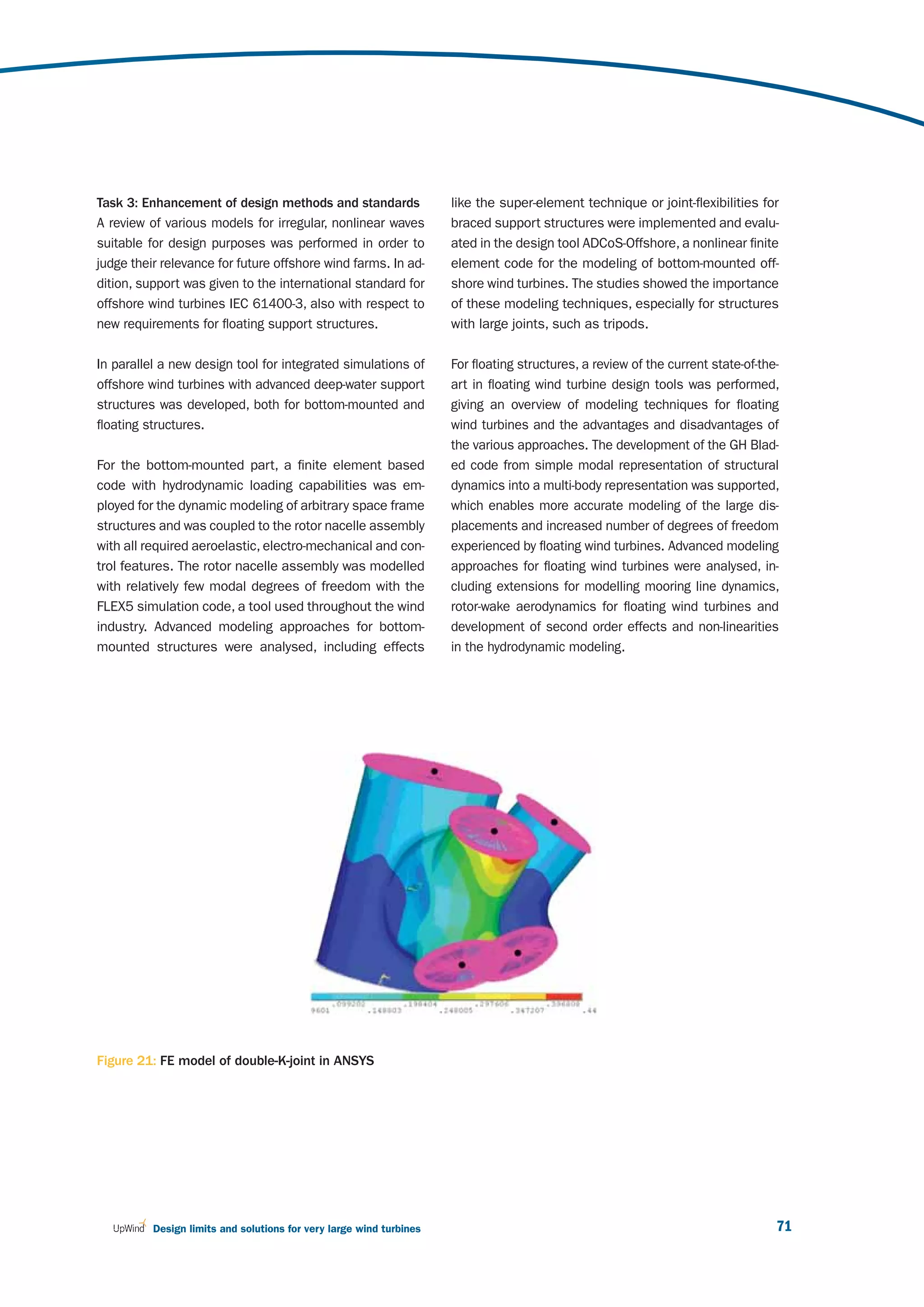
![Subtask C: Development of (pre)standards for the associated tests. Proposals will be submitted to the
application of the integral design approach International Organisation for Standards for all electri-
Broad standards were developed and formulated to cal, electronic and related technologies known as “elec-
clarify the design requirements of multi megawatt tur- trotechnologies” (IEC) /ISO (International Organisation
bines. Special emphasis has been put on probabilistic for Standardisation) and to the European Committee
design of wind turbines, and recommendations of how for Standardisation (CEN)/European Committee for
to implement research results in international design Electrotechnical Standardisation (CENELEC).
standards [7].
Special emphasis was put on the synthesis and ex-
A high reliability level and significant cost reductions trapolation of design load computations as required
are required so that offshore and land-based wind in IEC 61400-1, in order to arrive at efficient schemes
energy generation becomes competitive with other for the derivation of design fatigue and extreme loads
energy technologies. In traditional deterministic, code- (extrapolation of load effects).
based design, the structural costs are determined in
part by the safety factors, which reflect the uncertainty The IEC 61400-1 and -3 recommend identifying the 50
related to the design parameters. Improved design year extreme component load on the basis of limited
with a consistent reliability level for all components load simulations through the use of statistical extrapo-
can be obtained through probabilistic design methods, lation methods. Such methods are often the cause of
where uncertainties connected to loads, strengths and large variations in the extreme design load level. The
calculation methods are part of the calculation. In prob- possibility of determining a robust 50 year extreme
abilistic design, single components are designed to a turbine component load level when using statistical
level of safety, which accounts for an optimal balance extrapolation methods was investigated, so that the
between failure consequences, material consumption, 50 year load shows limited variations due to different
O&M costs and the probability of failure. Furthermore, turbulent wind seeds or inflow conditions. Case stud-
by using a probabilistic design basis, it is possible to ies of isolated high extreme out of plane loads were
design wind turbines so that site-specific information also dealt with, so as to demonstrate the underlying
on climatic parameters can be used. Probabilistic physical reasons for them. The extreme load extrapo-
design of structural wind turbine components can be lation methodology was made robust through the use
used for direct design of components, thereby ensur- of Principal Component Analysis (PCA) and simulation
ing a more uniform and economic design than that data from two widely used aeroelastic codes was
obtained by traditional design using standards such applied. The results for the blade root out of plane
as the IEC 61400 series. loads and the tower base fore-aft moments were
investigated as those extrapolated loads have shown
The IEC 61400-1 and -3 standards were reviewed wide variability in the past and are essential for turbine
within the UpWind project, and an assessment was design. The effects of varying wind directions and
made of design load computations and in particular the linear ocean waves on the extreme loads were also
needs related to very large wind turbines. The methods, included. Parametric fitting techniques that consider
topics and results identified by UpWind create the all extreme loads including “outliers” were proposed
need for the revision or development of international and the physical reasons that result in isolated high
standards for the design of wind energy plants and extreme loads were highlighted [8]. The isolation of
Design limits and solutions for very large wind turbines 25](https://image.slidesharecdn.com/upwindreport-121016072243-phpapp01/75/Upwind-Design-limits-and-solutions-for-very-large-wind-turbines-27-2048.jpg)
![2 UpWind: Scientific integration
the exact physical reasons that result in the peak procedure as the spread in the extreme out of plane
extreme component loads also led to the creation of loads at each mean wind speed is repeatable, unlike
simplified fast solvers to determine the 50 year out those that occur due to wind inflow variations. The
of plane load level, as opposed to the numerous aer- effect of soil flexibility further increases the mudline
oelastic simulations that are usually carried out. This extreme load level as lower frequencies have higher
was demonstrated for the offshore turbine mudline out out of plane load power spectral density. Therefore
of plane loads because simplified, fast and reason- the soil flexibility must be modelled while the offshore
ably accurate procedures enable the turbine designer foundation mudline ultimate design loads are deter-
to quickly understand the ultimate design limits [9]. mined [10].
The comparison of wave loading and wind loading on
offshore turbine mudline extreme loads showed that Subtask D: Integration, review and planning workshops
the significant influence on the mudline load was due In order to bring together the findings of the project’s
to the wind inflow, but the effect of the waves and soil work packages, workshops were regularly arranged with
conditions cannot be neglected. The wave loading was a special focus on the upscaling of turbines and the
seen to be mildly beneficial for the load extrapolation formulation of cost models.
References
[1] Chiciudean T.G., La Rocca G. and van Tooren [6] Natarajan A.: Extreme loads Extrapolation for
M.J.L.: A Know-ledge Based Engineering Offshore Turbines. Presented at the IEA 63rd
Approach to Support Automatic Design of Wind Topical Expert Meeting on High Reliability
Turbine Blades, CIRP Design Conference, Twente, Solutions & Innovative concepts for Offshore
The Netherlands, 2008. Wind Turbines, Sept 2010, Trondheim, Norway.
[2] Chiciudean T.G. and Cooper C.A.: Design of an [7] Sieros G., Chaviaropoulos P,. Sørensen J.D.,
Integral Pre-Processor for Wing-Like Structure Bulder B.H., and Jamieson P.: Upscaling Wind
Multi-Model Generation and Analysis. 27th Turbines: Theoretical and practical aspects and
International Congress of the Aeronautical their impact on the cost of energy. Submitted to
Sciences, Nice, Farce 2010. Wind Energy, 2010.
[3] Jonkman J., Butterfield S., Musial W., and Scott [8] Sørensen, J.D. and Toft H.S.: Probabilistic
G.: Definition of a 5-MW reference wind turbine design of wind turbines. Energies, Vol. 3,
for offshore system development, Tech. Report 2010, pp. 241-257.
NREL/TP-500-38060, National Renewable Energy
Laboratory (NREL), February 2009.
[9] Sørensen, J.D., Chaviaropoulos T., Jamieson P.,
Bulder B.H. and Frandsen S.: Setting the frame
[4] Natarajan A. & Verelst D.R.: Robustness of Wind for up-scaled offshore wind turbines. Taylor &
Turbine Extrapolated Extreme Loads, Submitted Francis, CD-rom proc. for ICOSSAR, Osaka, 2009.
to Wind Energy Journal, 2010.
[10] van Tooren M., La Rocca G. and Chiciudean T.G.:
[5] Natarajan A.: Computationally Efficient Further Steps to-wards Quantitative Conceptual
Determination of Long Term Extreme Aircraft Design. Variational Analysis and Aero-
Out-of-Plane Loads for Offshore Turbines. space Engineering, Volume 33, Springer New
Submitted to EWEC 2011, Brussels. York 2009.
26 March 2011](https://image.slidesharecdn.com/upwindreport-121016072243-phpapp01/75/Upwind-Design-limits-and-solutions-for-very-large-wind-turbines-28-2048.jpg)
![2 UpWind: Scientific integration
Results Advances in metrology
Metrology for wind energy is in rapid development.
The metrology database Some earlier EU projects considered measurement
The objective is to develop metrology tools to sig- methods in wind energy [3, 4], making progress on
nificantly enhance the quality of measurement and current cup and sonic anemometry, and some devel-
testing techniques. The first outcome is an assess- opment needs were identified for sonic anemometry.
ment of current measurement methods and problems. Requirements for detailed turbulence measurements
The required accuracies and sampling frequencies call for better procedures in international standards
were identified from the perspective of the data us- on sonic anemometer calibration and classification.
ers, and with regards to the UpWind objectives. The This task is currently considered in the revision work
information was categorised in groups according to on the IEC standard on performance measurements
current analysis techniques, current measurement [3], where cup anemometer calibrations and classifica-
techniques, a sensor list, derived problems and tions have already been implemented.
commercially available sensors. In order to process
these large amounts of data a database structure A significant contribution has been made on power per-
was designed and implemented. The database in- formance measurements with the influence of shear.
cludes eleven primary tables as shown on Figure 2. A method has been developed which has a good
The database is available on www.winddata.com as chance of being implemented in the ongoing revision of
part of a “database on wind characteristics” and for the IEC performance standard [5]. A turbulence norma-
UpWind partners in a portable MS-Access version. lisation method has been tested [7] but not found
Preliminary results are listed in [1] and a detailed efficient enough for inclusion in the IEC standard [5].
description of each table is listed in [2]. These methods have been tested on several existing
datasets, such as the Riso/DTU and ECN test sites.
Figure 2 : Metrology database structure. The database is accessible through www.winddata.com.
Application
Table=applications
AID
Condition parameters
Table=indication
Param No
State-of-art analysis technique State-of-art-technique Parameters
Table=methods Table=technique Table=parameters
MID, AID TID, Param No PID, AID, Param No
References Problems Parameter technique Sensor applications
Table=references Table=problems Table=params_tech Table=sensor_applications
RID, MID PRID, MID TID, PID PID, SID
Sensors
Table=sensor_types
SID, Param No
Commercial sensors
Table=commercial_sensor
CID, SID, Param No
28 March 2011](https://image.slidesharecdn.com/upwindreport-121016072243-phpapp01/75/Upwind-Design-limits-and-solutions-for-very-large-wind-turbines-30-2048.jpg)
![In relation to the coming IEC standard on performance For resource assessment, and replacing the tradi-
verification with the use of nacelle anemometry [8], tional measurement masts, UpWind demonstrated
nacelle anemometry has been studied, both the that the ground-based LIDAR measurement principle
theory and its practical application [9]. An alternative is efficient in flat terrain. In complex terrain and
to nacelle anemometry has also been developed, the close to woods, the measurement volume is dis-
so-called spinner anemometer [10, 11]. This type of turbed by a vertical turbulence component. Due to a
sensor seems to avoid the draw-backs of nacelle an- large measurement volume, ground-based LIDARs
emometry because the sensors are positioned in front perform a spatial averaging which has the effect of a
of the rotor on the spinner. Finally, mast correction low pass filter on turbulence measurements. This
measurement has also been developed to improve effect requires special attention and correction
current measurements [12]. methods, which were analysed within the UpWind
project by the use of the WAsP engineering tool,
With respect to new wind measurement technologies which is a computer based program for the estima-
such as remote sensing (LIDAR & SODAR), a substan- tion of extreme wind speeds, wind shears, wind pro-
tial number of projects have been undertaken over the files and turbulences in complex (and simple) terrain.
last five years. Ground based LIDARS have been devel- LIDAR measurements were made from a rotating
oped significantly, and in the past few years calibration spinner. The analysis show good perspectives for
and traceability issues have also been tackled and are scanning the incoming wind, which may lead to bet-
now being included in the IEC standard revision [5]. ter controlled wind turbines.
An overview is provided by [6], where significant metrol- LIDARs have also been used to scan the wake of
ogy contributions are described. wind turbines. These measurements show the
curvy wake pattern. Progress has been made with
Focus on LIDAR technology large-scale site wind scanning with three coordi-
LIDAR technology is relatively recent and requires nated LIDARs.
testing. Testing against a traditional meteorological
mast has been shown to be efficient for gaining Verification of anemometer calibrations
confidence and trust in measurement accuracy. In the context of MEASNET 9 a cup anemometer cali-
In principle, LIDAR measurements could be made bration round robin and acoustic noise measurement
traceable through the fundamental measurement round robin were performed [13] with good results for
principles, but at this stage of development it is not the associated MEASNET institutes. Together with
feasible. Instead, traceability is secured through the MEASNET experts, UpWind worked to try and
comparison with meteorological masts that are find a procedure for calibrating sonic anemometers.
themselves traceable through wind tunnel calibrations The operational characteristics of 26 sonic anemom-
of cup anemometers. LIDARs can fulfil different eters have been investigated over a long period of time
objectives: by [17]. Improvements were required in order to use the
sensors for wind energy applications. These improve-
ments are being implemented by the manufacturer.
9
Measnet: International network for harmonised and recognised measurements in wind energy.
http://www.measnet.com, MEASNET Round Robin (RR) on anemometer calibration is one method of measurement.
Design limits and solutions for very large wind turbines 29](https://image.slidesharecdn.com/upwindreport-121016072243-phpapp01/75/Upwind-Design-limits-and-solutions-for-very-large-wind-turbines-31-2048.jpg)
![2 UpWind: Scientific integration
Standardisation organisations require additional veri- A sensitivity analysis was carried out on the results.
fication measures for anemometers. The preferred The operation time on site, the annual mean wind speed,
method is to recalibrate the anemometers to verify the mean turbulence intensity and the annual mean tem-
that any possible degradation of the operational char- perature were examined. In order to reduce the statis-
acteristics of anemometers during their operational tical scatter, and identify possible interactions, the cases
period is kept within known limits. As an alternative studied were separated per anemometer type and binned
to recalibration, on site comparison was investigated. (categorised) per parameter type. It was seen that binned
Data was analysed from various in situ comparisons values for mean SSD with usage time have low depend-
of anemometer calibrations. As a measure of “anemo- ence, since a longer operation time would cause greater
meter degradation” the square sum of the Systematic degradation to anemometer bearings. However, for the
Deviation and the Statistical Deviation (SSD) between anemometer type examined here, (Vector A100 series)
the two operating periods is used. For the in situ com- the SSD values remain below the 0.1 m/s limit even for
parison to be considered successful, the SSD must usage time exceeding 365 days [14, 15]. No obvious
be lower than 0.1 m/s for each wind speed bin (a tool effect on deviation from site annual mean wind speed,
used to make samples of wind speed) in the range of mean turbulence intensity, or mean air temperature were
6 to 12 m/s. In situ comparisons were successful for detected for the covered parameter range. Therefore,
90% of the examined cases. Acceptable results were “in situ comparison” as described in [16] is a reliable tool
found even for anemometers operating for more than for the verification of anemometer calibration integrity.
18 months on site. Recalibrations of anemometers in
the wind tunnel after the end of the measurement cam-
paign were in full accordance with the in situ results.
Figure 3 : SSD values as a function of operation time on site (only cases with Vector A100 series anemometers)
0.16 16
6 to 7
0.14 14
9 to 10
11 to 12
0.12 12
IEC61400-12-1
Sample per bin h
Mean SSD
SSD (m/sec)
0.1 10
Samples per bin
0.08 8
0.06 6
0.04 4
0.02 2
0 0
0 200 400 600 800
Days of use
30 March 2011](https://image.slidesharecdn.com/upwindreport-121016072243-phpapp01/75/Upwind-Design-limits-and-solutions-for-very-large-wind-turbines-32-2048.jpg)
![References
[1] Dahlberg J.A., et.al., “Classcup – Development of [11] Pedersen T.F., Wagner R., et al, Risø-R-1752,
a standardized cup anemometer suited to wind “UPWIND Metrology 1A2.3 – Advancements in
energy applications”, JOULE 2001. Wind Energy Measurement Methods”, 2010.
[2] Diznabi B., Investigation of the flow relation [12] N. Stefanatos, P. Papadopoulos, E. Binopoulos,
to nacelle anemometry, To be published Master A. Kostakos, G. Spyridakis, "Effects of long term
Thesis, March 2009, MEK-FM-EP-2009-03 operation on the performance characteristics of
(not published). cup anemometers” Proc. Of EWEC 2007, Milan.
[3] Eecen P.J., Stefanatos N., Petersen S.M., and [13] N. Stefanatos, A. Kostakos, P. Papadopoulos,
Hansen K.S., UPWIND METROLOGY; Deliverable E. Binopoulos, "Verification of anemometer
D 1A2.1 List of Measurement Parameters, calibrations” Proc. Of EWEC 2010, Warsaw.
ECN-E--07-015.
[14] J.W. Wagenaar, P.J. Eecen, Gill Windmaster Sonic
[4] Eecen P.J., Stefanatos N., Pedersen T.F. and Anemometers, ECN-X--09-144.
Hansen K.S., UPWIND METROLOGY; Deliverable
D 1A2.2 Metrology Database, ECN-E--08-079.
[15] J.W. Wagenaar, P.J. Eecen, Measurements of Wind,
Wave and Currents at the Offshore Wind Farm
[5] Eecen P.J., and Wagenaar W.J., MEASNET Egmond aan Zee, ECN-E--09-015.
Anemometer Calibration Round Robin 2009,
Analysis of MEASNET reference wind speed,
ECN-X-10-067. [16] J.W. Wagenaar, P.J. Eecen, 3D Turbulence at
the Offshore Wind Farm Egmond aan Zee,
ECN-E--10-075.
[6] Eecen P.J., 6th MEASNET Round Robin; Sound
Power Level and Tonality, ECN-X--07-146.
[17] “Accuwind – Accurate wind speed measurements
in wind energy”, Risø-R-1563(EN), JOULE 2006.
[7] Frandsen S., Sørensen J.N., Mikkelsen R.,
Pedersen T.F., Antoniou I., Hansen K.,
The generics of wind turbine nacelle [18] IEC61400-12-1, 2005, “Wind Turbines-Part 12-1:
anemometry, EWEC 2009. Power performance. measurements of electricity
producing wind turbines”.
[8] Lindelöw-Marsden P., Pedersen T.F., Gottschall
J., Vesth A., Wagner R., Paulsen U., Courtney [19] IEC61400-12-2-CD “Wind Turbines-Part 12-2:
M.S., Flow distortion on boom mounted cup Power performance. measurements of electricity
anemometers, Risø-R-1738(EN), 2010. producing wind turbines with the use of nacelle
anemometry”.
[9] T.F. Pedersen, N.N. Sørensen, P. Enevoldsen
Aerodynamics and characteristics of a spinner [20] MEASNET Measurement Procedure:
anemometer, The Science of Making Torque from Cup Anemometer Calibration, Ver. 2 2009.
Wind, August 2007, DTU.
[10] T.F. Pedersen, L. Vita, N.N. Sørensen,
P. Enevoldsen, Operational experiences with a
spinner anemometer on a MW size wind turbine,
EWEC 2008.
Design limits and solutions for very large wind turbines 31](https://image.slidesharecdn.com/upwindreport-121016072243-phpapp01/75/Upwind-Design-limits-and-solutions-for-very-large-wind-turbines-33-2048.jpg)


![References
[1] Ashwill T.D. and Paquette J.A., “Composite [9] Fragoulis, A., MOUNTURB: Load and Power
Materials For Innovative Wind Turbine Blades”, Measurement Program on Wind Turbines
Wind Energy Technology Department, Sandia Operating in Complex Mountainous Regions,
National Laboratories, Albuquerque, NM. Final Report for JOU2-CT93-0378 CEU project,
1996.
[2] Brøndsted P., Lilholt H., and Lystrup A.,
“Composite Materials For Wind Power Turbine [10] Fragoulis, A., COMTER.ID: Investigation of
Blades”, Materials Research Department, Risoe Design Aspects and Design Options for Wind
National Laboratory, Denmark, April 2005 “MIL- Turbines.
HDBK-17-3F”, Department of Defense, US, June
2002.
[11] Operating in Complex Terrain Environments,
Final Report for JOR3-CT95-0033 CEU project,
[3] Bruhn E.F.. Analysis and Design of Flight Vehicle 1998.
Structures. Jacobs publishing, Inc. Indianapolis.
1973.
[12] Frazao O. (INESC), Romero R. (INESC), Santos
J.L. (INESC, Universidade do Porto). Simultaneous
[4] Burton T., Sharpe D., Jenkins N. Y, Bossanyi E. Measurement of Temperature and Strain using
Wind Energy Handbook. Wiley. 2001. Ring Fiber Bragg Grating Sensors. OFS 16 2003.
[5] Chaviaropoulos, P.K., “Flap/Lead–lag Aero-elastic [13] García R. (Univ. Politécnica de Valencia), Sales
Stability of Wind Turbine Blades,” Wind Energy, S. (Univ. Politécnica de Valencia), Capmany
2001, 4, 183–200. J. (Univ. Politécnica de Valencia), Warzanskyj
W. (Telefónica I+D), McDonald D. (Intune
Technologies), Bastiani M. (Ecoazioni). A new
[6] Chaviaropoulos, P., Politis, E.S., Lekou, D.J., interrogation system for a large number of strain
Sorensen, N. N, Hansen, M., Bulder, B. H., sensors using Fiber Bragg Grating for application
Winkelaar, D., Lindenburg, C., Saravanos, D.A., in residential buildings. II European Workshop
Philippidis, T.P., Galiotis, C., Hansen, M.O.L., on OFS 2004.
Kossivas, T., “Enhancing the Damping of Wind
Turbine Rotor Blades, the DAMPBLADE Project,”
Wind Energy, 2006, 9, 163–177. [14] Gdoutos E.E.; Daniel I.M.; Wang K.-A.
Compression facing wrinkling of composite
sandwich structures. ELSEVIER. January, 2002.
[7] Doyle C. (Smart Fibres). Fibre Bragg Grating
Sensors, An introduction to Bragg gratings and
interrogation techniques, 2003. [15] Griffin, D.A., “Blade System Design Studies
Volume I: Composite Technologies for Large
Wind Turbine Blades”,. SAND2002-1879, Sandia
[8] Dutton A.G. (ERU), Blanch M.J. (ERU), Vionis National Laboratories, Albuquerque, NM.
P. (CRES), Lekou D. (CRES), van Delft D.R.V.
(Delft University), Joosse P.A. (Delft University),
Anastassopoulos (Envirocoustics Abee), Kossivas [16] Griffin, D.A., “Blade System Design Studies
T. (Geobiologiki S.A.), Philippidis T.P. (University Volume II: Preliminary Blade Designs and
of Patras), Kolaxis Y.G. (University of Patras), Recommended Test Matrix”, SAND2004-0073,
Fernando G. (Cranfield University), Proust A. Sandia National Laboratories, Albuquerque, NM.
(Euro Physical Acoustics, S.A.), Acoustic Emission
Monitoring during Certification Testing of Wind
Turbine Blades. (AEGIS Project), February 2003. [17] Jones R. M. Mechanics of Composite Materials.
Scripta Book Co. Washington D.C. 1975.
Design limits and solutions for very large wind turbines 41](https://image.slidesharecdn.com/upwindreport-121016072243-phpapp01/75/Upwind-Design-limits-and-solutions-for-very-large-wind-turbines-43-2048.jpg)
![3 UpWind: Technology integration
[18] Kristensen O.J.D., McGugan M., Sendrup P., [25] Parton H. ‘Characterisation of the in-situ
Rheinlander J., Rusborg J., Hansen A.M., polymerisation production process for
Debel C.P., Sorensen B.F., Fundamentals for continuous fibre reinforced thermoplastics’, PhD
Remote Structural Health Monitoring of Wind Thesis, KU Leuven, February 2006.
Turbine Blades Annex E – Full-Scale Test of Wind
Turbine Blade, Using Sensors NDT, RISO-R-
1333(EN), May 2002. [26] Riziotis V.A., Voutsinas S.G., “GAST: A General
Aerodynamic and Structural Prediction tool
for Wind Turbines,” Proceedings of the 1997
[19] Lading L., McGugan M., Sendrup P., Rheinlander European Wind Energy Conference & Exhibition,
J., Rusborg J., Fundamentals for Remote Dublin, Ireland.
Structural Health Monitoring of Wind Turbine
Blades Annex B – Sensors and Non-Destructive
Testing Methods for Damage Detection in Wind [27] Riziotis V.A., Voutsinas S.G., Politis E.S.,
Turbine Blade s, RISO-R-1341(EN), May 2002. Chaviaropoulos P.K., “Assessment of Passive
Instability Suppression Means on Pitch-regulated
Wind Turbines,” Wind Energy, 1008, 11, 171-192.
[20] Lystrup A., ‘Vacuum consolidation of
thermoplastic composites for wind turbine rotor
blades’, Proceedings of the 27th RisøInternational [28] Riziotis V.A., Voutsinas S.G. “Dynamic stall on
Symposium on Materials Science, September wind turbine rotors: comparative evaluation
2006, p231-238. study of different models,” Proceedings of the
1997 European Wind Energy Conference &
Exhibition, Dublin, Ireland.
[21] Mandell J.F, Samborsky D.D., Li M. Orozco
R., and Cairns D.S., “Selection Of Fiberglass
Matrix Resins For Increased Toughness And [29] Riziotis V.A., Voutsinas S.G., Politis E.S.,
Environmental Resistance In Wind Turbine Chaviaropoulos P.K., “Aeroelastic Stability of
Blades”, Department of Chemical Engineering Wind Turbines: The Problem, the Methods and
and Department of Mechanical Engineering, the Issues,” Wind Energy, 2004, 7, 373–392.
Montana State University, Bozeman, MT.
[30] Schepers J.G., Snel, H., Joint Investigation of
[22] Markou H., Hansen M.H., Buhl T., van Engelen Dynamic Inflow Effects and Implementation of
T., Politis E.S., Riziotis V.A., Poulsen,N.K., Larsen, an Engineering Method for Response Analysis,
A.J., Mogensen, T.S., Holierhoek, J.G., “Aeroelastic ECN Report ECN-C-94-107, the Netherlands, 1994.
Stability and Control of Large Wind Turbines –
Main Results,” Proceedings of the 2007 European [31] Schepers J.G., Snel, H., Dynamic Inflow: Yawed
Wind Energy Conference & Exhibition, Milan. Conditions and Partial Span Pitch Control, ECN
Report ECN-C-95-056, The Netherlands, Final
[23] Niu M.C.Y., Airframe Structural Design. Technical Report for JOU2-CT92-0186 CEU project, 1995.
Book Company, 1988.
[32] Schepers J.G., VEWTDC: Verification of European
[24] Niu M. Composite airframe structures. Hong Wind Turbine Design Codes, Final Report for
Kong Conmilit press LTD. Hong Kong. January JOR3-CT98-0267 Joule III project, ECN, 2001.
1992, Third edition June 2000.
42 March 2011](https://image.slidesharecdn.com/upwindreport-121016072243-phpapp01/75/Upwind-Design-limits-and-solutions-for-very-large-wind-turbines-44-2048.jpg)
![[33] Schlotter M., “A Comparison of Core Materials for [41] Zingraff L. et al., ‘Resin transfer moulding
Sandwich Composite Constructions”. June, 2002. of anionically polymerised polyamide 12’,
Composites Part A, Vol. 36, Issue 12,
December 2005, pages 1675-1686.
[34] Sundaresan M.J. (NREL), Shulz M.J. (NREL),
Ghoshal A. (NREL), Structural Health Monitoring
Static Test of a Wind Turbine Blade, August 1999. [42] DS 472. Code of practice for loads and safety of
wind turbine constructions. The Danish Society
of Engineers and the Federation of Engineers.
[35] Teuwen J., ‘Vacuum infused thermoplastic 1992.
composites for wind turbine blades’, Presentation
at Wind Turbine Blade Workshop, Sandia
National Laboratories, 12-14 May 2008. [43] Gamesa Structures Manual (FSM).
[36] Tsai S.W.; Hahn, H. T. Introduction to Composite [44] Germanischer Lloyd – Rules and Regulations.
Materials. Technomic Publishing Company. Non Marine Technology. Regulations for the
Wesport.1980. Certification of Wind Energy Conversions
Systems. 2003.
[37] Van Rijswijk K., Bersee H.E.N., ‘Reactive
processing of textile fiber-reinforced [45] IEC 61400-1 Ed.3: Wind Turbine Generator
thermoplastics – An overview’, Composites: Systems – Part 1: Safety Requirements.
Part A, 2006. International Electrotechnical Commission.
Mayo, 2005.
[38] Van Rijswijk K., Bersee H.E.N., Beukers A.,
Picken S.J., Van Geenen A.A., ‘Optimisation [46] IEC 61400-1 Ed.3: Wind turbines - Part 1:
of anionic polyamide-6 for vacuum infusion Design requirements. International
of thermoplastic composites: Influence of Electrotechnical Commission. Mayo, 2005.
polymerization temperature on matrix properties’,
Polymer Testing, volume 25, 2006, p392-404.
[47] IV-1 Guideline Certification Wind Turbines.
Ed. 2003, sup. 2004. Germanischer Lloyd Wind
[39] Van Rijswijk K., Bersee H.E.N., Beukers A., Energie. 2004.
Picken S.J., Van Geenen A.A., ‘Optimisation of
anionic polyamide-6 for vacuum infusion of
thermoplastic composites: Choice of activator and [48] TPI Composites, Inc. “Innovative Design
initiator’, Composites: Part A, volume 37, 2006, Approaches for Large Wind Turbine Blades Final
p949-956. Report: WindPACT Blade System Design Studies”
Sandia National Laboratories: Albuquerque, NM.
SAND 2004-0074, Mayo 2004.
[40] Verghese K.E., “Durability of Polymer Matrix
Composites for Infrastructure: The Role of the
Interphase”, in Materials Engineering Science.
1999, Virginia Polytechnic Institute and State
University: Blacksburg, VA.
Design limits and solutions for very large wind turbines 43](https://image.slidesharecdn.com/upwindreport-121016072243-phpapp01/75/Upwind-Design-limits-and-solutions-for-very-large-wind-turbines-45-2048.jpg)
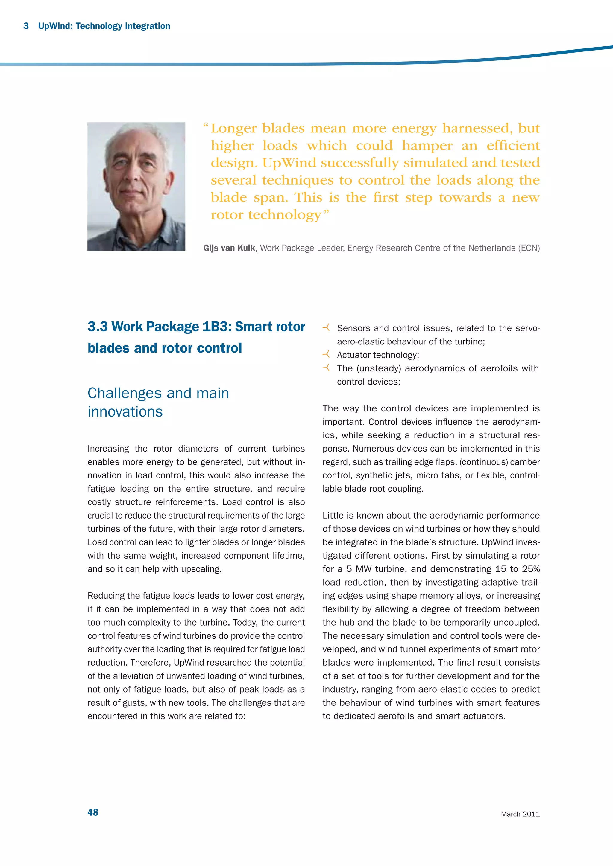
![250
Generator total active mass
Abbreviations
Copper mass
U: U-core shape
Stator core mass
CP: claw poles
200 PM mass
Rotor core mass 1..8: number of slots per phase
L: limited axial length
A: limited pole area
Active mass [ton]
150
100
50
0
RFPM
TFPM-U
TFPM-CP/1/L
TFPM-CP/2/L
TFPM-CP/4/L
TFPM-CP/8/L
TFPM-CP/1/A
TFPM-CP/2/A
TFPM-CP/4/A
TFPM-CP/8/A
Generator type
Figure 8: Active mass comparison of different 10 MW PM generators.
Power electronics offering the most potential for future developments.
While acknowledging that doubly-fed induction genera- Currently the lack of tailor-made power semiconduc-
tors are almost standard today, the UpWind research tors is a substantial drawback. The three-level NPC is
focused on full converter solutions for synchronous a well established converter topology for the desired
generators. Three different approaches to increase the output power range, and it supports different out-
power rating to the required level were analysed in de- put voltage levels. The parallel interleaved converter
tail. An example of a design approach including power topology provides very good harmonic performance at
device selection, selection of switching frequency, filter the grid interface. The improvements on the harmonic
design, efficiency curve, volume estimates and control performance are achieved at the expense of some ad-
scheme was drawn up. These concepts include the ditional circulating currents. A fact common to all three
matrix converter, the three-level neutral point clamped topologies is that the highest conversion efficiency is
(NPC) converter and the parallel interleaved converter. achieved with the use of low voltage semiconductors
(1700V IGBTs). However from the point of view of total
As a result of the benchmarks it can be noted that all system cost there is a tendency to aim for voltages
topologies are potential candidates for next genera- that are as high as possible to decrease transformer
tion wind turbines and can serve the desired power and conductor costs.
conversion rating. The matrix converter is the topology
Design limits and solutions for very large wind turbines 47](https://image.slidesharecdn.com/upwindreport-121016072243-phpapp01/75/Upwind-Design-limits-and-solutions-for-very-large-wind-turbines-49-2048.jpg)
![3 UpWind: Technology integration
Task 3: Control systems
A system for the control of spanwise distributed devices
was developed. Moreover, several control tasks, mainly
regarding the placement of sensors and the develop-
ment of algorithms, were carried out in Task 4.
Task 4: Smart wind turbine wind tunnel model
A scaled turbine was built for wind tunnel research. This
was used to research the feasibility of different load
control concepts in the project (notably camber control
and the ‘smart’ blade-hub interface) and to validate tur-
bine models.
In wind tunnel experiments, a large load reduction poten- Figure 10: The scale model of a smart rotor in the wind
tial was observed – up to 60% in the standard deviation tunnel. The flaps are the silver area‘s in the outboard
of the strain root sensor. section of the blade.
1
0,5
MFC signal [V]
0
-0,5
-1
0 0,1 0,2 0,3 0,4 0,5 0,6 0,7 0,8 0,9 1
Figure 11: Wind tunnel tests on a scaled smart rotor – flapwise root bending moment with (black) and without flap
activation (yellow).
50 March 2011](https://image.slidesharecdn.com/upwindreport-121016072243-phpapp01/75/Upwind-Design-limits-and-solutions-for-very-large-wind-turbines-52-2048.jpg)
![Task 5: Interfaces
Researching the feasibility of ’smart interfaces’. These
interfaces would allow a degree of freedom between the
hub and the blade (the torsional blade, in this case),
which could be temporarily uncoupled. This could allevi-
ate gust loads since during uncoupling the aerodynamic
moment will pitch the blade to feather as the DoF is
released. The load alleviation potential of the concept
was researched in this task. The results show that the
system can be very effective in alleviating gust loads
as can be seen below.
Blade out of plane bending moment at root
(thick lines: clutch activated, thin lines: no action)
14
12
8
MY x 10-6
4
0
1st blade
-4
2nd blade
3rd blade
-8
0 2 4 6 8 10 12 14 18 18 20
Time [s]
Figure 12: Gust load reduction potential with a torsional "clutch" in the blade-hub-interface.
Design limits and solutions for very large wind turbines 51](https://image.slidesharecdn.com/upwindreport-121016072243-phpapp01/75/Upwind-Design-limits-and-solutions-for-very-large-wind-turbines-53-2048.jpg)


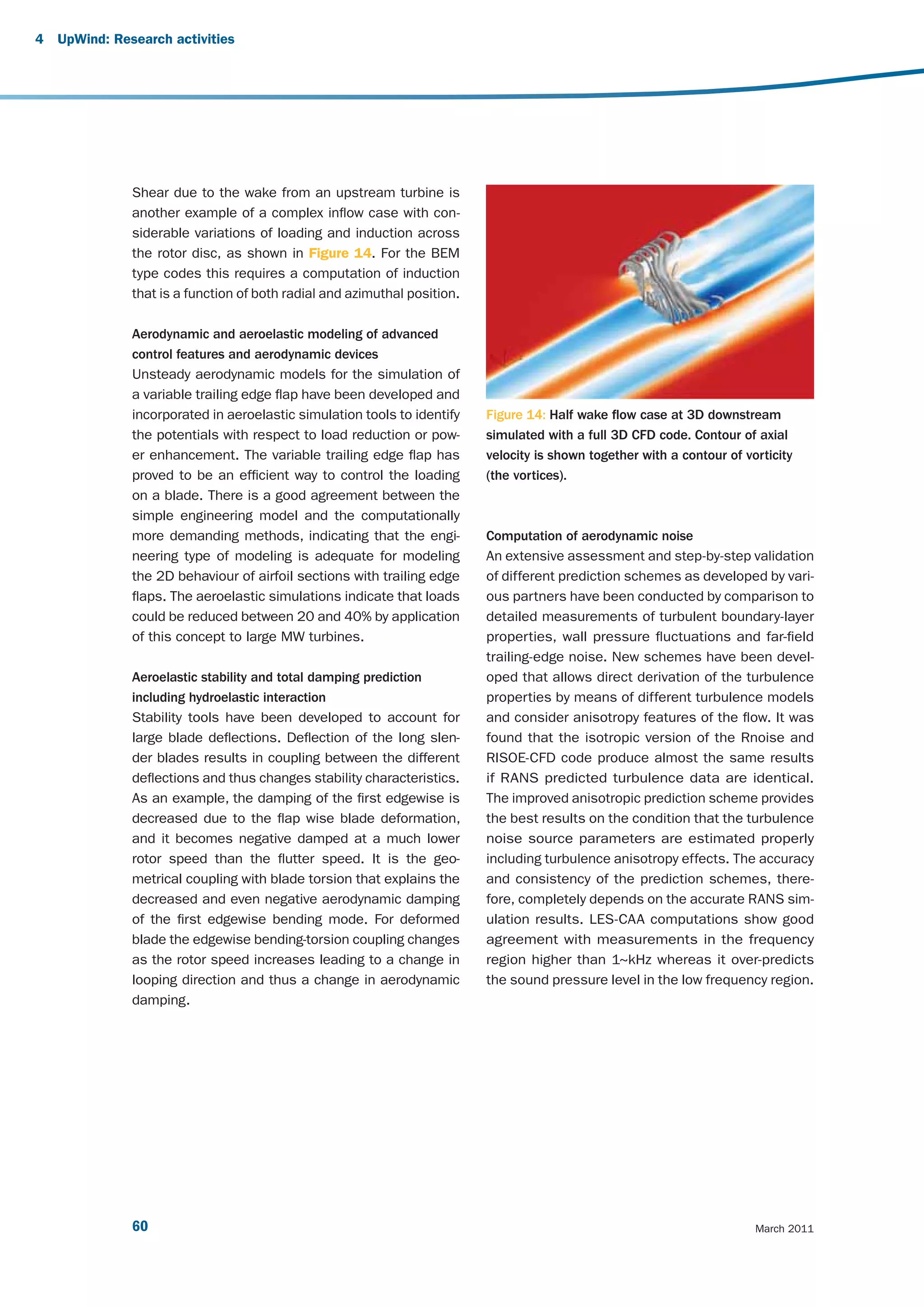
![Engineering aerodynamic models by application So-fore blade pre-bend reduces torsion loads and
of full 3D unsteady CFD models in complex inflow increases the blade stability. On the contrary, aft pre-
such as strong wind shear were analysed and bend reduces the damping of the low damped edge-
developed. There, stability analysis including non- wise modes. Pre-sweeping the blades also drives a
linear effects (and structural modal damping pre- bending/torsion coupling which leads to nose down
diction) show that coupling effects are important; torsion deformation and reduced fatigue loads in aft
Overview of requirements to aerodynamic and pre-sweep configurations. The opposite effect is ob-
aeroelastic design tools in order to predict the tained for forward sweep.
potential of different advanced control features
and aerodynamic devices. Here, dynamic stall
1st order beam
models for the variable trailing edge concept were 1 2nd order beam - 0
developed and applied for aeroelastic predictions. 2nd order beam - 1
2nd order beam - 2
Torsion angle et blade tip [deg]
Fatigue load reductions of 20 – 40% have been
identified; 0,5
Development of concepts to improve the link
between CFD and aeroacoustic predictions.
Results show boundary layer predictions and 0
measurements are in reasonable agreement
with advanced UpWind methods.
-0,5
Research activities and results
-1
0 5 Time [s]
10 15 20
Structural dynamics — large deflections and
Time [s]
non-linear effects
Aeroelastic tools that account for important non- Figure 13: Predicted torsional deformation of blade
linear structural and geometric effects were devel- (5 MW) by beam model taking different nonlinear
oped and applied to estimate the importance for effects into account.
loads and stability of the blades. The structural
modelling capabilities were advanced by developing Advanced aerodynamic models
new beam models that account for the detailed inner Results from different levels of aerodynamic models
structure (complex laminates and sandwich skins). have been compared. The advanced models show
It was identified that the torsional deformation was that the induction varies for the blade in different
affected by the coupling of the blade torsion with the azimuthal positions when there is shear in the in-
blade bending and should be taken into account in flow, due to the skew vortex sheets. BEM models
the modeling of large flexible blades. should be implemented such that they model the
local inflow and load distribution on the rotor. Another
This is illustrated in Figure 13, which shows that flow mechanism observed in the simulations of inflow
the tip pitch is up to about one degree different due with strong shear is a considerable interaction with
to non-linear effects. With respect to the geometri- the ground. There is a speed-up of the flow below
cal non-linearities, it was found that the bending- the rotor due to the constraint from the ground on
torsion coupling drives differences in the response the flow expansion. This means that the ground influ-
of pre-curved blades as compared to straight ones. ences the aerodynamics of the rotor.
Design limits and solutions for very large wind turbines 59](https://image.slidesharecdn.com/upwindreport-121016072243-phpapp01/75/Upwind-Design-limits-and-solutions-for-very-large-wind-turbines-61-2048.jpg)

![4 UpWind: Research activities
Results 700
100
1,000
Amplitude of cyclic stress [MPa]
600
Task 1: Applied (phenomenological) material model 10,000
In order to serve as a basis for advanced material mod- 100,000
500
1,000,000
els, the existing OPTIDAT database is extended with 10,000,000
400
new materials. The results of this task enable valida-
tion of the models derived in task 2 and serve as input 300
data for UpWind activities. Together with the work car-
200
ried out in 2, the result is an integrated material model,
based on both tests and micro-mechanics, for which 100
design recommendations and material test recommen- 0
- 800 - 600 - 400 - 200 0 200 400 600 800 1000
dations are established, Figure 15.
Mean cyclic stress [MPa]
Test methods for static compression, fatigue and static
shear were reviewed and compared qualitatively and Figure 15: Constant life diagram
quantitatively. These results provide valuable input for
refinement of test procedures and design recommenda-
tions. optical strain measurement techniques. The possibility
of embedded strain gauges was the subject of strength
Extensive experimental work was done at off-reference and fatigue experiments.
conditions, performing tests on reference specimens in
an attempt to decouple the temperature and frequency A structure, representing a structural blade detail, e.g.
effects, for use in the integral material model. shear web/spar cap construction, was manufactured,
tested, analysed numerically and with the assistance
In collaboration with the Condition Monitoring activities, of NDT methods, to improve understanding of the struc-
research was carried out on the applicability of fibre tural behaviour of this detail, Figure 16.
Figure 16: Subcomponent testing and modelling
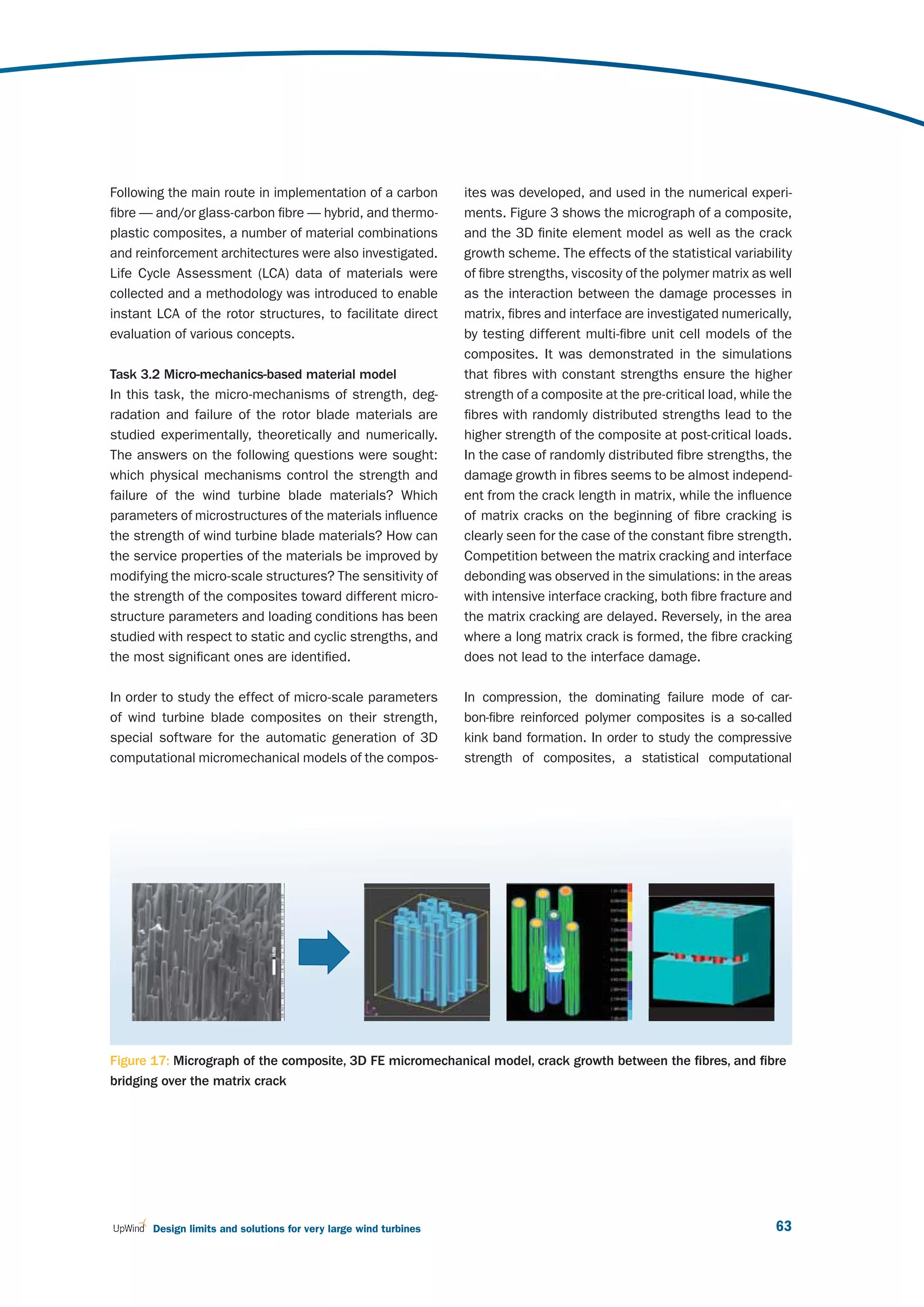
62 March 2011](https://image.slidesharecdn.com/upwindreport-121016072243-phpapp01/75/Upwind-Design-limits-and-solutions-for-very-large-wind-turbines-64-2048.jpg)
![4 UpWind: Research activities
model was developed on the basis of the Monte-Carlo Task 3.3: Damage-tolerant design concept
method and the Budiansky-Fleck fibre kinking condition. Nowadays, fibre reinforced plastics (FRP) rotor blades
The effects of fibre misalignment variability, fibre cluster- are designed according to regulations based on very
ing and load sharing rules on the damage in composite first principles of composite mechanics, in which ply
are studied numerically. It was demonstrated that the failure of a multilayer element in a finite element (FE)
clustering of fibres has a negative effect of the damage model is not followed by property degradation and
resistance of a composite. Further, the static compres- thus, investigation of post-FPF (first ply failure) load
sive loading model is generalised for the case of cyclic bearing capability is not implemented. Furthermore,
compressive loading, with and without micro-degradation material constitutive equations are considered lin-
of the matrix, and with and without random variations of ear, although it is common knowledge that in-plane
loading. It was observed that the random variations of shear and transverse compressive response of a
loading shorten the lifetime of the composite: the larger uniform direction layer is from moderately to highly
the variability of applied load, the shorter the lifetime. non-linear.
The model was further generalised to include the irregu-
lar fibre waviness and the interface defects. Considering The objective of the work performed was to formulate
the cases of small and large interface defects with differ- and develop a shell-based finite element numerical
ent density, we observed that the small interface micro- methodology for life prediction, as well as residual
cracks do not lead to the sufficient reduction of com- strength and stiffness of wind turbine rotor blades
pressive strength even at unrealistically high micro-crack made of FRP subjected to irregular cyclic loads. In
,
density. In contrast, large interface defects have a strong this task therefore, a continuum damage mechanics
effect on the compressive strength of the composite. method was implemented in a ply-to-laminate life pre-
diction scheme for composite laminates under cyclic
In the computational studies of the effects of micro- constant amplitude (CA) or variable amplitude (VA)
structures of rotor blade materials on their strength loading. Instead of considering the geometric descrip-
and damage resistance, it was observed that a weaker tion of a type of defect induced by local failure, a set
fibre/matrix interface prevents the development of ma- of appropriate stiffness degradation rules was applied,
trix cracks in the composites. Further, replacement of resulting in a modified stiffness tensor, i.e. an equiva-
fibre reinforcements by clusters or bundles of thinner lent, homogeneous, continuum description, such that
fibres can ensure higher strength of the composite. either the resulting strain field or strain energy density
The effect of the loading frequency on the lifetime of under the same load is similar to that of the damaged
materials depends strongly on the damage mecha- medium.
nisms: whether it is rate-dependent or creep-related
damage. Generally, the micro scale analysis and micro- An extensive comparison of life prediction numerical
structure optimization represent an important source results with experimental data from CA or VA tensile
of the optimization of the wind blade materials. And cyclic testing of a [±45]S plate and loading at vari-
potential review of the safety factors for large blades ous R-ratios of a multidirectional (MD) Glass/Epoxy
should include an analysis of the material properties. laminate [(±45/0)4/±45]T has been performed.
64 March 2011](https://image.slidesharecdn.com/upwindreport-121016072243-phpapp01/75/Upwind-Design-limits-and-solutions-for-very-large-wind-turbines-66-2048.jpg)
![Figure 18: Damage modes according to Puck failure criteria of a [(±45/0)4/±45] Gl/Ep MD coupon, at a stress
level of σmax=193 [MPa], R=0.1
As an example, in Figure 18 damage patterns in the two methodologies were developed within task 3.3,
outer three layers of an MD coupon after 700,000 where the probability of failure is estimated on the
cycles were shown. layer level, taking into consideration the variability of
applied loads, material strength and elasticity proper-
Additionally, quantification of the structural reliabil- ties. One, based on the Edgeworth Expansion method,
ity level of the wind turbine blade with respect to its allows for direct connection with currently employed
strength, stiffness and elastic stability should be per- aero-elastic wind turbine design codes, while the other,
formed in probabilistic terms by relying both on load employing the Response Surface Method in combina-
uncertainty quantification as well as on material, due tion with a finite element shell model, allows a more
to the use of composite materials, exhibiting great in- accurate representation of the blade structure.
herent variability of mechanical properties. To this end,
Design limits and solutions for very large wind turbines 65](https://image.slidesharecdn.com/upwindreport-121016072243-phpapp01/75/Upwind-Design-limits-and-solutions-for-very-large-wind-turbines-67-2048.jpg)

![Wind farms can be utilised to provide voltage con- increases can be mitigated by appropriate supervisory
trol for the network to which they are connected. control design. For example, Figure 22 shows how the
A supervisory VAR controller has been developed severe increase in yaw moment due to IPC during a grid
for a large-scale wind farm to control the voltage loss shutdown can be entirely mitigated by phasing out
at the point of interconnection (POI) with the grid. IPC during periods of high acceleration.
Strategies for detecting failures of individual blade load
Results sensors were also investigated. If undetected, these could
result in significant fatigue load increases if IPC action
Supervisory control implications of advanced control continues regardless. Often the sensor itself would detect
Individual pitch control (IPC) is a promising technique for its own failures, allowing the IPC to be switched off, but
reducing wind turbine asymmetric fatigue loads by pitch- an undetected failure case should still be considered.
ing each blade individually in response to load measure- The work has shown that by comparing the mean and
ments. However there is also a risk of increasing extreme peak values of the differences between measured blade
loads as the blades might be pitched at different angles loads over each revolution, the controller can detect such
during shutdowns, or as a result of failures of individual a malfunction with a suitable degree of reliability, obviat-
load sensors. This work shows how these extreme load ing this risk.
Collective pitch Individual pitch (basic) Individual pitch, phasing out with rotor acceleration
6000
4000
2000
0
Tower Mz [kNm]
- 2000
- 4000
- 6000
- 8000
- 10000
- 12000
0 5 10 15 20 25 30
Time [s]
Figure 22: Effect on loads of phasing out IPC with rotor acceleration
Design limits and solutions for very large wind turbines 75](https://image.slidesharecdn.com/upwindreport-121016072243-phpapp01/75/Upwind-Design-limits-and-solutions-for-very-large-wind-turbines-77-2048.jpg)
![Wind speed (upperline); rotor speed at dual and single pitch (no difference)
18
[RPM] , [M/S]
16
14
12
10
Pitch angle at dual/single pitch control (fat-lines/thin-line)
20
15
[DEG]
10
5
Blade root flap moment; level-at/reduction-by dual pitch (fat/thin line)
6
[MNm]
4
2
0
Blade root flap moment; percentual reduction by dual pitch relative to single-pitch-mean
20
[%]
10
0 100 200 300 400 500 600
Time [s]
Figure 24: Simulation with single and dual pitch control
Dual pitch control for out of plane blade load reduction the total torque and the total thrust can be adjusted
When pitch control is used to regulate rotor torque, the independently. This was demonstrated in a simulation
rotor thrust also changes, causing fatigue loading and using an additional actuator at 66% span. As shown
excitation of tower dynamics. One task was to inves- in Figure 24, by pitching the tip section more than the
tigate whether a dual-pitch blade, which has full-span root section a 15% reduction in the underlying flapwise
pitch control with an additional pitch actuator allowing loading (excluding the component due to rotational
the outer part of the blade to pitch relative to the inner sampling) is achieved without any effect on the speed
part, could be used, adjusting both actuators simul- regulation.
taneously so that as the wind speed changes, both
Design limits and solutions for very large wind turbines 77](https://image.slidesharecdn.com/upwindreport-121016072243-phpapp01/75/Upwind-Design-limits-and-solutions-for-very-large-wind-turbines-79-2048.jpg)
![25
v [m/s]
20
15
10
10 15 20 25 30
30
ß [deg]
20
10
5
10 15 20 25 30
14
Ω [pm]
12
10
8
10 15 20 25 30
12
My T [Nim]
8
4
0
-4
10 15 20 25 30
Time [s]
Figure 26: Amelioration of gust response with LIDAR feed-forward
LIDAR assisted collective pitch control measurements were simulated with Bladed and the
As WP6 shows, the accuracy of LIDAR systems has in- UpWind controller was extended by an additional pitch
creased to the point where it may be feasible to use rate demand increment calculated from these simulat-
them for wind turbine control, by providing a preview of ed measurements. An example is shown in Figure 26.
wind disturbances at various distances in front of wind The upper plot shows the actual wind gust (black) and
turbines. LIDAR measurement (grey). Below this are the collective
pitch angle, rotor speed and tower base fore-aft bend-
This information can be used to improve control per- ing moment for the UpWind controller only (black) and
formance using a predictive feed-forward control struc- with LIDAR-based feedforward (grey), showing significant
ture. To estimate the load reduction of extreme and improvement.
fatigue loads by LIDAR assisted pitch control, LIDAR
Design limits and solutions for very large wind turbines 79](https://image.slidesharecdn.com/upwindreport-121016072243-phpapp01/75/Upwind-Design-limits-and-solutions-for-very-large-wind-turbines-81-2048.jpg)
![4 UpWind: Research activities
02050340 OFF 02020007 ON
Validation of load reducing controllers in full-scale 12.42m/s 21.55%TI 12.09m/s 20.70%TI
field tests
An important task of the UpWind project is to use field 1.0e+10
tests to demonstrate that the very significant load
reductions predicted with individual pitch control (IPC) 1.0e+09
can really be achieved in practice. Previously the only
1.0e+08
published results came from simulation models, so
field test results are vital for increasing confidence of
1.0e+07
turbine designers to use IPC in their new designs. Field
tests of an advanced controller were carried out on
3.0e+06
the two-bladed ‘Controls Advanced Research Turbine’ 0.0 0.5 1.0 1.5 2.0 2.5 3.0 3.5 4.0 4.5 5.0
Frequency [Hz]
(CART2) at NREL in Colorado, USA. This demonstrated
conclusively that both IPC and fore-aft tower damping Figure 27: Spectra showing reduction of 1P shaft bend-
work effectively and as predicted. Figure 27 shows ing moment with IPC
spectra of the measured shaft bending moments dur-
Bin averages (showing number of points)
ing similar wind conditions with and without IPC, clearly 280
1
demonstrating the elimination of the 1P load peak. 260
OFF
2
ON
By calculating damage equivalent loads, for 127 cam- 2
240 2
paigns of up to 10 minutes each and binning these 4 2
3
Shaft My SN4 [kNm]
220 4
against wind speed, Figure 28 clearly demonstrates 1
1
the consistent reduction in fatigue loading with IPC ON 200
7 31
1 1
compared to OFF. No adjustment of the as-designed 180 6
4
controller was required, demonstrating the robustness 160
5 1
of this technique. 3
5 6 3
140 2 3 6 2
10
120 1
The field tests also provided the opportunity to test a 4
2 6
100
fore-aft tower damping algorithm, and as shown in Fig- 4 6 8 10 12 14 16 18 20
Mean wind speed [m/s]
ure 29 this also showed excellent performance, with a
large reduction of loading at the first tower frequency. Figure 28: Binned results showing reduction of damage
equivalent loads with IPC
This field test programme is now being extended to the
02050340 OFF 02020007 ON
three-bladed CART3 turbine. Field tests are also being 12.42m/s 21.55%TI 12.09m/s 20.70%TI
completed on a REpower turbine to test both fore-aft 9.0e+11
and side-side damping algorithms.
1.0e+11
1.0e+10
1.0e+09
1.0e+08
0.0 0.5 1.0 1.5 2.0 2.5 3.0 3.5 4.0 4.5 5.0
Frequency [Hz]
Figure 29: Spectra showing reduction of fore-aft tower
bending moment
80 March 2011](https://image.slidesharecdn.com/upwindreport-121016072243-phpapp01/75/Upwind-Design-limits-and-solutions-for-very-large-wind-turbines-82-2048.jpg)
![12
10
Blade 1 pitch angle [deg]
8
6
4
2
0
-2
0 10 20 30 40 50 60
Time [s]
Figure 30: Comparison of hardware-in-the-loop simulation (black) against pure simulation (blue) in turbulent wind.
Hardware-in-the-loop testing of pitch actuators actuator test bed via xPC-Target. With this setup, more
Simulations with hardware-in-the-loop can verify the confidence can be gained in understanding the impact
system performance much better than a pure com- of individual pitch control on the pitch actuator perfor-
puter simulation. A test rig has been set up with the mance, but the technique has the potential to improve
IWES pitch actuator test bed providing three real pitch understanding also of other wind turbine components.
actuators, linked to a Bladed computer simulation of Performance of the pitch system under several wind
the rest of the turbine and the incident wind field using conditions have been run using the hardware-in-the-loop
the GH Hardware Test package to provide a conveni- pitch actuators, and validated against a pure computer
ent interface. A MATLAB/SIMULINK simulation of the simulation in the same conditions. The comparison
pitch bearing and gearing uses blade loads from the of turbulent wind simulations in Figure 30 shows that
real-time Bladed simulation to transfer the load to the excellent agreement has been obtained.
Design limits and solutions for very large wind turbines 81](https://image.slidesharecdn.com/upwindreport-121016072243-phpapp01/75/Upwind-Design-limits-and-solutions-for-very-large-wind-turbines-83-2048.jpg)
![4 UpWind: Research activities
Potència activa Potència reactiva total filtrada
4000 2500
3500 assaig
Potència reactiva [kW]
2000 simulaciò
Potència activa [kW]
3000
2500 1500
2000
1000
1500
1000 assaig 500
simulaciò
500
0
0
-500 -500
19 19.5 20 20.5 21 19 19.5 20 20.5 21
temps [s] temps [s]
Figure 31: Comparison of measured and simulated active power (left) and reactive power (right)
Riding through grid faults Impact of the drive train on wind farm VAR Control
Doubly-fed induction generators (DFIG) have been Wind farms can be utilised to provide voltage control for
widely used on wind turbines because of their well- the network to which they are connected. A supervisory
known generator and power converter technologies VAR controller has been developed for a large-scale
and a relatively low cost. To ensure fulfilment of the wind farm to control the voltage at the point of intercon-
different grid code requirements while simultaneously nection (POI) with the grid. Its use in conjunction with
ensuring that load envelopes are not exceeded in grid different types of generator and converter systems has
fault situations, it is important to be able to model the been investigated, including doubly-fed induction gener-
DIFG accurately in conjunction with the aerodynamics, ators (DFIG) modelled on the GE 1.5/3.6 MW systems,
structural dynamics and controller dynamics of the and synchronous generators connected to the grid
wind turbine. To achieve this, a model of the electrical through a full converter as on the GE 2.5 MW machine.
and control parts of the DFIG has been developed and This has also been compared to a directly-connected
linked into a Bladed model of the turbine using the DLL synchronous generator system. For synchronous ma-
interface provided. As well as the generator and con- chines, both static and brushless excitation systems
verter controller, the model includes a chopper resistor were investigated, and two different VAR control strate-
which is switched in and out according to DC link volt- gies were investigated. The study has shown that grid
age, and a crowbar protection system which cuts in if a short circuit ratio is an important consideration, and
further over-voltage is detected. The combined model also that it is important to monitor the number of wind
has then been validated using field measurements of turbines connected at any one time. With well-tuned
voltage dip ride-through tests on an actual ECO100 control parameters, the VAR control performance with
turbine and comparing the measurements against the conventional synchronous machines could have
simulated results for these cases. Good agreement similar time responses to that obtained with the DFIG
has been obtained, giving some confidence in using machine type with power electronics grid interface or
this model to optimise the performance. Figure 31 full power converter interfaces.
shows a comparison of measured and simulated
active and reactive power.
82 March 2011](https://image.slidesharecdn.com/upwindreport-121016072243-phpapp01/75/Upwind-Design-limits-and-solutions-for-very-large-wind-turbines-84-2048.jpg)
![References
[1] Bossanyi E. Controller field tests on the NREL [5] Jasniewicz B. (2010) Online estimation of
CART2 turbine, GH Report 11593/BR/08, www. mechanical load for wind turbines. Upwind
upwind.eu/Paginas/Publications/5%20Control%20 Deliverable 5.3
systems.aspx.
[6] Savini B., Bossanyi E.A. “Supervisory Control
[2] Bossanyi E.: Controller for 5MW reference Logic Design for Individual Pitch Control”, Poster
turbine, GH report 11593/BR/04, 2009: www. presented at EWEC 2010, Warsaw Poland, April
upwind.eu/Shared%20Documents/WP5%20 %20 20-23 2010.
Publications/D%205.1.1.%20Controller%20for%20
5MW%20reference%20turbine.pdf.
[7] Schlipf D., Trabucchi, D., Bischoff O., Hofsäß M.,
Mann J., Mikkelsen T., Rettenmeier A., Trujillo J.
[3] Hau M. (2008). Promising load estimation J., and Kühn M.: Testing of Frozen Turbulence
methodologies for wind turbine components. Hypothesis for Wind Turbine Applications with
Upwind Deliverable 5.2 a Scanning LIDAR System, Proc. ISARS, Paris,
France, 2010.
[4] Iribas M., Landau I.D. Identification of wind
turbines in closed loop operation in the presence
of three dimensional turbulence wind speed.
Wind Energy Journal 2009; 12:660-675.
Design limits and solutions for very large wind turbines 83](https://image.slidesharecdn.com/upwindreport-121016072243-phpapp01/75/Upwind-Design-limits-and-solutions-for-very-large-wind-turbines-85-2048.jpg)

![More specifically, the objectives of UpWind are to answer Results
the questions – can remote sensing techniques substitute
conventional towers with the precision required by the UpWind has contributed very significantly to the de-
IEC standards, and how do we best exploit the freedom velopment of remote sensing for wind energy. Impor-
to measure detailed profiles offered by remote sensing tant results have been accomplished, in particular in
techniques? UpWind demonstrated the following points: the areas of SODAR calibration, bi-static SODAR de-
With LIDARs, power curve measurements can be sign, LIDAR testing, the use of LIDARs in complex ter-
performed on very large wind turbines without rain, power curve testing using remote sensing and the
masts. The best LIDARs measure wind speeds with understanding of the turbulence sensed by LIDARs.
an accuracy close to that of cup anemometers. Ultimately many of these advances have contributed to
Within UpWind, a verification procedure for compar- the improvement and modernisation of standards and
ing LIDARs to mast-mounted cup anemometers has best practices, most notably the IEC 61400-12-1 power
been developed. performance standard revision.
For very large turbines, wind shear should be taken
into consideration in power curve measurements. Apart from the more formal work, UpWind has func-
The equivalent wind speed method developed in tioned as an important European remote sensing
UpWind, achieves this aim and improves power forum, especially within the field of LIDAR development.
curve repeatability. IEC 61400-12-1 will probably Work package meetings have included a number of partici-
be modified to account for the effect of shear using pants from outside the project group, both from industry
an equivalent wind speed and allowing the use of and other research institutes.
remote sensing to measure wind profiles.
Including speed profiles in power curves for large SODAR–calibration and design improvements
turbines will also require full profile measurements A central aim has been to develop techniques for the in-
for the resource assessment. LIDARs are ideal for situ calibration of SODARs. One idea that has been devel-
this task, particularly when the power consumption oped in the project is to build a transponder system that
and reliability issues have been tackled. simulates the acoustic response of the atmosphere to the
LIDAR errors in complex terrain are now well un- transmitted signal under different speed and shear condi-
derstood and can be predicted if the local flow tions [8]. This system has been found to be a useful tool
can be modelled reasonably well. Complex terrain for laboratory quality control and investigation of SODAR
‘correction’ tools are now standard options with behaviour but has practical limitations in real-life field envi-
commercial wind LIDARs. ronments. A much simpler system that can measure the ef-
An important and emerging aspect of LIDAR tech- fective beam tilt angles by using in-situ tilting of the SODAR
nology will be the use of nacelle-mounted LIDARs. has been proposed and tested with promising results [3].
Wind turbines may in the future, incorporate LIDARs
in their design, allowing pre-emptive control of the Bi-static SODAR designs, where the transmitter and
blades based on the details of the approaching receiver are physically separated, are much more sensitive
wind, hence reducing the blade loads. Another im- than mono-static SODAR and can have significant advan-
portant application for nacelle-mounted LIDARs will tages in complex terrain. Under the auspices of UpWind,
be for measuring reference wind speeds in connec- a scanning bi-static SODAR design has been proposed
tion with power and load certification. [1]. Successful testing has been carried out in flat terrain
and the system will soon undergo trials in mountainous
landscape. Several commercial bi-static SODAR designs
are now beginning to emerge.
Design limits and solutions for very large wind turbines 85](https://image.slidesharecdn.com/upwindreport-121016072243-phpapp01/75/Upwind-Design-limits-and-solutions-for-very-large-wind-turbines-87-2048.jpg)
![4 UpWind: Research activities
LIDAR testing in flat terrain LIDAR measurements in complex terrain
Comparisons of measurements from remote sensing Wind LIDARs use an assumption of horizontally homogene-
devices with mast measurements are our main tool for ous flow in order to calculate the horizontal wind speed.
assessing the performance of LIDARs and SODAR. In flat Whilst this is a good assumption in flat terrain, in complex
terrain, the assumption of flow homogeneity inherent in the terrain the flow is rarely horizontally homogeneous and con-
design of SODAR and LIDAR profilers is fulfilled, giving the sequently significant errors can occur in the measurement
best possible comparison to mast-mounted instruments. of the horizontal wind speed. A major result for UpWind has
Concentrating on wind LIDARs that are still rather new and been to propose a scheme using flow models to predict
technologically immature has been a major task in UpWind and correct for the error [2]. Major wind LIDAR manufac-
and has provided important synergy to other EU projects tures now offer such an error correction scheme based
using LIDARs, notably NORSEWInD and SafeWind. on CFD modeling as optional services for their products.
Indisputably, the LIDAR testing carried out under UpWind Power curve testing
has provided important feedback to the LIDAR manufactur- Power curve measurements require wind speed meas-
ers. For example it has been identified that the deflection urements at the hub-height of the wind turbine. As wind
angles of the prisms used in both the major wind LIDAR turbines increase in size and height, this requirement
types were too imprecise. New procedures for individually alone makes ground-based LIDAR or SODAR anemometry
measuring the prism cone angles have resulted in signifi- more attractive. At the same time, with increasing rotor
cant improvements in LIDAR precision. Thorough analyses diameter, the concept of correlating wind turbine power
of LIDAR error sources have been undertaken within Up- production to a single, hub-height wind speed becomes
Wind [6] and these findings have been used both to im- more and more suspect. It is now well accepted that the
prove LIDARs and to improve the LIDAR testing procedure. wind speed profile has a significant effect on the power
In flat terrain, many wind LIDARs provide consistently high production and an equivalent wind speed method has
correlations to reference cup anemometers [4]. been proposed to include the influence of the speed
shear [11]. Measurements have shown a significant
As LIDARs have improved, so too has the demand for ac- reduction in scatter when the power is plotted as a function
curate testing. The need to validate a whole wind speed of the equivalent wind speed rather than the hub-height
profile as opposed to a speed at a single height im- wind speed [12]. Uncertainty budgets show that a remote
poses unprecedented demands on the accuracy of boom- sensing device with a very high correlation to the reference
mounted cup anemometers. A new scheme using two cup cup anemometer is required.
anemometers mounted on two identical but differently
pointing booms at one height has recently been proposed
[7] which significantly reduces the uncertainty of boom-
mounted cup anemometer measurements.
86 March 2011](https://image.slidesharecdn.com/upwindreport-121016072243-phpapp01/75/Upwind-Design-limits-and-solutions-for-very-large-wind-turbines-88-2048.jpg)
![Figure 32: Commercial LIDARs undergoing test at Høvsøre, Denmark. UpWind has contributed significantly to wind
LIDAR development and testing.
IEC 61400-12-1 revision LIDAR and reference. In UpWind, this has been examined
Many of the results from UpWind are contributing to the both theoretically and experimentally.
modernization of the strategically important power curve
standard, IEC 61400-12-1. For very large rotors, UpWind Firstly, the turbulence measured by a ‘staring’ LIDAR (one
demonstrated that measuring the wind speed at a single constant line of sight as opposed to scanning) has been
location leads to significant errors in power curve measure- compared with that measured from an adjacent sonic
ments. Instead, the wind profile over the entire rotor should anemometer [10]. Good agreement was found. For a
be taken into consideration. A method estimating the conically scanning LIDAR, several mechanisms combine to
equivalent wind speed was developed and demonstrated. attenuate the wind speed standard deviation observed by
The equivalent wind speed method is proposed as a cen- the LIDAR. A model including the spatial averaging both
tral component for the revised standard. Since remote sen- along the lines of sight and around the scanning circumfer-
sors are obvious tools for measuring wind speed profiles, ence has been proposed and compared to experimental
UpWind is also contributing concepts and methods for measurements [13]. Whilst generally good agreement is
LIDAR verification including a rigorous proposal for LIDAR found, the LIDAR and cup anemometer standard devia-
uncertainty [5]. tions are still very scattered. An even more rigorous model
including the contribution from all three components of
LIDAR turbulence measurements turbulence has recently been proposed [9]. Here it is
At a prospective wind energy site, the turbulence inten- found that the ratio between LIDAR and cup anemometer
sity is often as important to ascertain as the actual wind turbulence intensity varies markedly both with height and
resource. LIDAR testing has shown that, even when the atmospheric stability. Using current LIDAR designs, it is
mean wind speed is highly correlated to a reference cup impossible to accurately measure the horizontal turbu-
anemometer measurement, the standard deviations of lence intensity unless a sonic anemometer, giving the ratio
wind speed are much less well correlated between the between the three turbulence components, is present.
Design limits and solutions for very large wind turbines 87](https://image.slidesharecdn.com/upwindreport-121016072243-phpapp01/75/Upwind-Design-limits-and-solutions-for-very-large-wind-turbines-89-2048.jpg)
![4 UpWind: Research activities
References
[1] Behrens P., Bradley S., A Scanning Bi-static [8] Piper B., von Hünerbein S., The Development of
SODAR . ISARS 2008, Roskilde Denmark. a Transponder Based Technique for the Acoustic
Calibration of SODARs, ISARS 2008, Roskilde
Denmark.
[2] Bingöl, F. et al. Conically scanning LIDAR error
in complex terrain. Meteorologische Zeitschrift.
2009; vol. 18, no. 2, p. 189-195. [9] Sathe A., Mann J., Gottschall J., Courtney M.S.,
Estimating the systematic errors in turbulence
sensed by wind LIDARs Submitted to JTECH,
[3] Bradley S., Robust, “blind”, in-situ calibration of September 2010.
SODARs, ISARS 2008, Roskilde Denmark.
[10] Sjöholm, M. et al. Spatial averaging-effects on
[4] Courtney M.S., Lindelöw P., Wagner R., LIDAR turbulence measured by a continuous-wave
profilers for wind energy – The state of the coherent LIDAR. Meteorologische Zeitschrift
art. Windpower 2009, American Wind Energy Band. June, 2009; vol. 18, no. 3, p. 281 – 287.
Association, Chicago, 2009.
[11] Wagner R., Antoniou I., Petersen S.M., Courtney
[5] Gottschall J., Wagner R., Courtney M., Jørgensen M., Jørgensen H.E.., The influence of the Wind
H., Antoniou I., LIDAR profilers in the context Speed Profile on Wind Turbine Performance
of wind energy – A verification procedure for Measurements, Wind Energy, 12,issue: 4, 348-362,
traceable measurements, submitted to Wind (2009).
Energy, September 2010.
[12] Wagner R., Courtney M., Gottschall J., Lindelöw
[6] Lindelöw-Marsden P., UpWind D1. Uncertainties –Marsden P. Accounting for the wind speed
in wind assessment with LIDAR, Risø-R-1681, shear in wind turbine power performance
Risø2008. measurement, submitted to Wind Energy,
July 2009, currently under revision.
[7] Lindelöw-Marsden P. et al. Investigation of flow
distortions on boom mounted cup anemometers [13] Wagner R., Mikkelsen T., Courtney M.
on a lattice tower – proposal of correction Investigation of turbulence measurements with
algorithm and in-field calibration method, a continuous wave, conically scanning LiDAR,
submitted to Wind Energy, September 2010. EWEC 2009, Marseille, France.
88 March 2011](https://image.slidesharecdn.com/upwindreport-121016072243-phpapp01/75/Upwind-Design-limits-and-solutions-for-very-large-wind-turbines-90-2048.jpg)

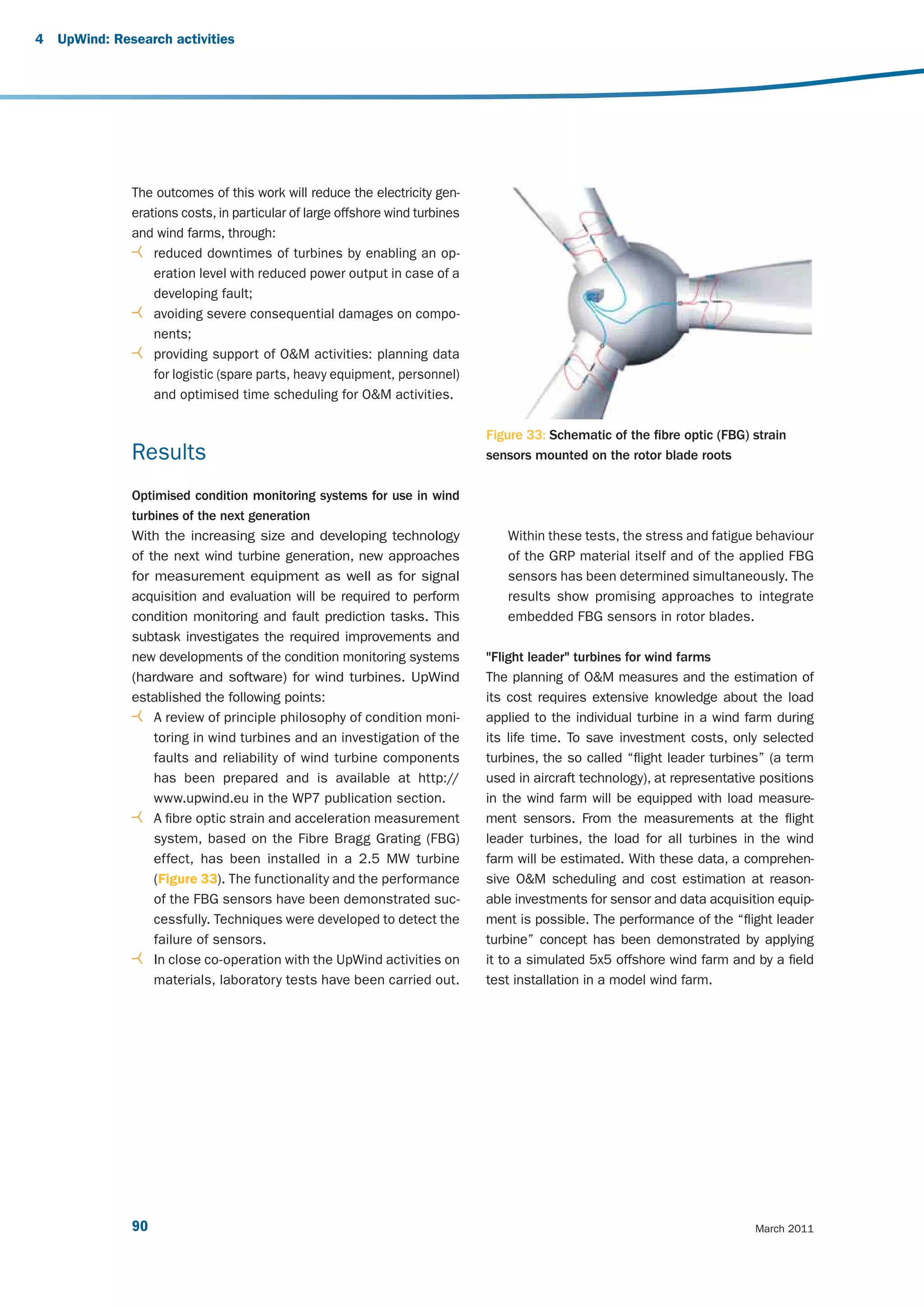
![Annual downtime [days] remaining life time [%]
0
20
40
60
80
100
120
Ge
0
ar
0
0,1
0,2
0,3
0,4
0,5
0,6
0,7
0,8
0,9
1
b
Bl ox
Ge e ad ot
he
Ge arb bea r
ne ox rin
ra be g
to ar
r b in
e g
M ari
ai ng
0,2
Ro n
to sh
r a
Ge bea ft
ar rin
Break down
wh g
e
Az Ge els
im ar
Drive Train
ut rin
(∑ 2,6 days)
Components
In be g
te
0,4
rm Co arin
ed up g
Dr iat ling
ive e S s
Cyclic
tra ha
in fts
ot
Bl he
Design limits and solutions for very large wind turbines
ad r
e
st
ru
0,6
Bl
ad ctu
Hu es re
b oth
st
r er
Bl uctu
at
e re
Time / MTBF [-]
Hu bolt
b s
To Fou othe
Condition based
0,8
we nd r
Figure 35: Components of variable speed wind turbines and their reliabilities
Structural
Na Hou r in atio
(∑ 1,8 days)
Components
ce sin cl. n
lle g bo
su str lts
pp uc
or tur
tf e
ra
m
Fr
Ge e
eq ner
1
ue ato
nc r
Bl y c oth
ad on er
e ve
Figure 34: Maintenance and repair strategies with respect to condition/reliability based approach
Ge pitc rter
ne h d
Reliability based
ra riv
Sl t e
ip Az or c
rin im oli
Electrical
gs ut s
1,2
(∑ 3,1 days)
Components
/ dri
br ve
us
he
s
91](https://image.slidesharecdn.com/upwindreport-121016072243-phpapp01/75/Upwind-Design-limits-and-solutions-for-very-large-wind-turbines-93-2048.jpg)
![References
[1] Caselitz P., Giebhardt J., "Rotor Condition [9] Tavner; P.; et al.: ‘Influence of wind speed on
Monitoring for Improved Operational Safety of wind turbine reliability‘; Wind Engineering;
Offshore Wind Energy Converters", Journal of Volume 30; No. 1; 2006.
Solar Energy Engineering, Pages 253 - 261,
New York, May 2005.
[10] Final public report of the EC project
OffshoreM&R, Brussels, 2006; (Web-Link:
[2] Faulstich, S. et al; ‘Appropriate failure statistics http://www.iset.uni-kassel.de/osmr/download/
and reliability characteristics‘; DEWEK 2008; FinalPublicReport_OSMR.pdf).
Bremen
[11] Research project ‘Offshore~WMEP’;
[3] Institut für solare Energieversorgungstechnik www.offshore-wmep.de; funded by the Federal
(Hrsg.), Faulstich et al, ‘Windenergie Report for the Environment, Nature Conversation and
Deutschland 2008’, Kassel, 2008. Nuclear Safety.
[4] Faulstich S., Hahn B.: ‘Comparison of different [12] Standard IEC61500-25, Parts 1 to 6,
wind turbine concepts due to their effects on http://www.iec.ch/, 2010, Geneva, Switzerland.
reliability’, UpWind, EU supported project nr.
019945(SES6), deliverable WP7.3.2, public report,
Kassel, 2009. [13] Technical Guideline VDI 3834, “Part 1:
Measurement and evaluation of the mechanical
vibration of wind energy turbines and their
[5] Hahn, B.; Jung, H.: ‘Improving wind turbine components - Onshore wind energy turbines
availability by reliability based maintenance’, with gears”, Beuth-Verlag, 2009, Berlin, Germany.
DEWEK 2006, Bremen.
[14] VGB PowerTech (Editor), Richtlinie
[6] Hahn, B.; Giebhardt, J.; ‘Identification of suitable ‘Referenzkennzeichensystem für Kraftwerke
statistics about failure rates, MTBF and resulting RDS-PP – Anwendungserläuterungen für
downtimes for Wind Turbines‘; UpWind, EU Windkraftwerke‘ (Guideline Reference
supported project nr. 019945(SES6), deliverable Designation System for Power Plants, RDS-PP,
WP7.3.1, public report, Kassel, 2007. Application in Wind Turbines), VGB-B 116 D2,
2006.
[7] Obdam, T., Rademakers, L., Braam, H., “Flight
Leader Concept for Wind Farm Load Counting [15] Upwind-Report “Condition Monitoring for Wind
and Performance Assesment”, EWEC 2009, Turbines – State of the Art”, Brussels, 2008
Marseille, France. (Web-Link: http://www.upwind.eu/Shared%20
Documents/WP7%20-20Publications/UpWind-
WP7_SOTA_CMS.pdf ).
[8] Simpson E.H.: The Interpretation of Interaction
in Contingency Tables. In: Journal of the Royal
Statistical Society. Series B (Methodological) 13
(1951), Nr. 2, S. 238–241.
Design limits and solutions for very large wind turbines 93](https://image.slidesharecdn.com/upwindreport-121016072243-phpapp01/75/Upwind-Design-limits-and-solutions-for-very-large-wind-turbines-95-2048.jpg)
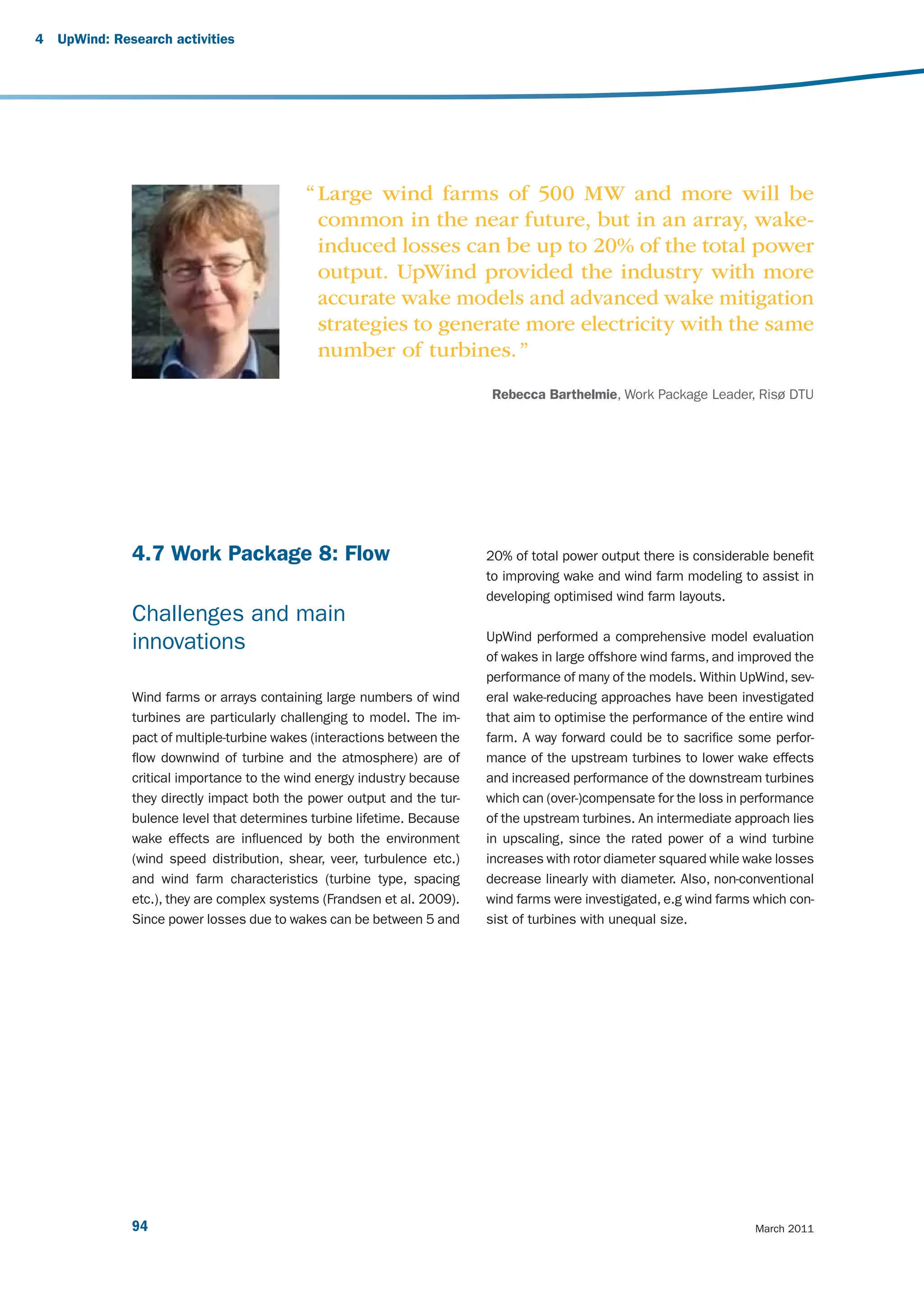
![Results UpWind performed a comprehensive model evalu-
ation of wakes in large offshore wind farms using
An important task in UpWind has been to analyse the data described above and the range of models
data for model verification and to categorise turbine (shown in Table 2). During the course of the project, the
wake losses to identify the most important parameters performance of many of the models was improved
based on SCADA data, which was recorded on three (e.g. (Rathmann et al. 2007, Schlez & Neubert 2009)).
types of wind farms ranging from a small onshore wind An example result is shown in Figure 36 (Barthelmie
farm (five turbines) located in flat terrain, a complex et al. 2010). The main finding can be summarised as
terrain wind farm (43 turbines) and three large offshore acknowledging that wake losses in the centre of large
wind farms (80 turbines, 72 turbines and 36 turbines). wind farms offshore are larger than modeled using
The offshore climate analysis shows a clear correlation standard wind farm model parameterizations but, once
between atmospheric stability, ambient turbulence and corrected, model results were improved in comparison
power deficit (e.g. Hansen et al. 2010). For example, with data from existing data sets.
the maximum power deficit for three different wind
turbines spacing shows a consistent relationship
decreasing with increasing turbulence intensity.
Name Company Type
WAsP Risø DTU Engineering
WindFarmer GH CFD-Ainslie
“Canopy” Risø DTU Under development
Wakefarm ECN Parabolised CFD
CFDWake CENER CFD
CRES-flowNS CRES CFD
NTUA NTUA CFD
Table 2: Wake and wind farm models evaluated in UpWind
90 90
Wind fam efficiency [100%]
Wind fam efficiency [100%]
80 80
70 70
60 Obs. 60
WindFarmer
Wakefarm
WAsP k=0.04
50 Nysted 50 Horns-Rev
NTUA
8.0+0.5ms-1 8.0+0.5ms-1
-15 -10 -5 0 5 10 15 -15 -10 -5 0 5 10 15
Degrees from wake centre Degrees from wake centre
Figure 36: Summary wake model evaluation for specific wind speed of 8.0±0.5 ms-1 and directions at Horns Rev
and Nysted. The wake centre refers to 270o at Horns Rev and 278o at Nysted (according to Barthelmie et al. 2010).
Design limits and solutions for very large wind turbines 95](https://image.slidesharecdn.com/upwindreport-121016072243-phpapp01/75/Upwind-Design-limits-and-solutions-for-very-large-wind-turbines-97-2048.jpg)
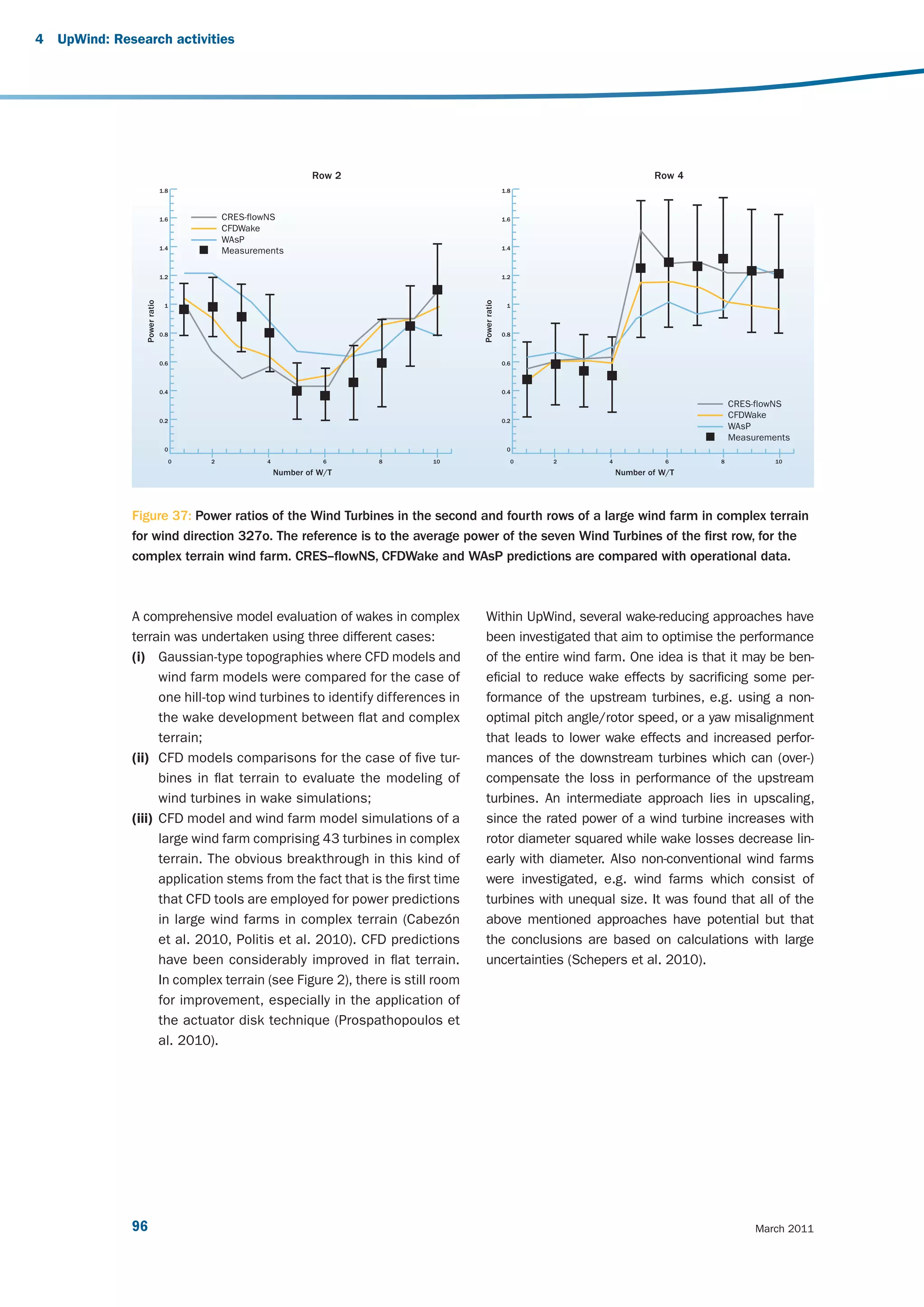
![Typical wind farm layout optimisations operate by using for overall cost including loading, three new key concepts
the energy yield as a target function. While leading to have been implemented. This allows us to optimise the
layouts with maximum energy yield, this can be less than layout of a large wind farm with respect to an economic
optimal for the project economics, due to increased tur- target function, reduce the turbine loads and vary turbine
bine loading and associated cost. To optimise a layout types to find the most economic layout.
References
[1] Barthelmie R.J., Pryor S.C., Frandsen S.T., [5] Politis E., Prospathopoulos J., Cabezón D.,
Hansen K., Schepers J.G., Rados K., Schlez W., Hansen K., Chaviaropoulos P., Barthelmie R.
Neubert A., Jensen L.E., Neckelmann S. (2010) (2010) Modeling wake effects in large wind farms
Quantifying the impact of wind turbine wakes on in complex terrain: the problem, the methods and
power output at offshore wind farms. Journal of the issues. Wind Energy (WE-10-0103, submitted
Atmospheric and Oceanic Technology 27:1302- 2 July 2010).
1317.
[6] Prospathopoulos J.M., Politis E.S., Chaviaropoulos
[2] Cabezón D., Hansen K., Barthelmie R.J. (2010) P.K., Rados K.G., Schepers J.G., Cabezón D.,
Analysis and validation of CFD wind farm Hansen K.S., Barthelmie R.J. (2010 ) CFD
models in complex terrain. Effects induced Modeling of Wind Farms in Flat and Complex
by topography and wind turbines EWEC 2010 Terrain. In: van Kuik G (ed) Proceedings of
scientific proceedings, Warsaw, Poland, April the 2010 European Wind Energy Conference &
2010, p 7. Exhibition, Warsaw, 20-23 April 2010, p 23-27.
[3] Frandsen S., Barthelmie R.J., Jorgensen H.E., [7] Rathmann O., Frandsen S.T., Barthelmie R.J.
Rathmann O., Badger J., Hansen K., Ott S., (2007) Wake modeling for intermediate and large
Rethore P., Larsen S.E., Jensen L. (2009) The wind farms. European Wind Energy Conference
making of a second-generation wind farm and Exhibition, Milan, May 2007, p 8.
efficiency model-complex. Wind Energy 12:431-
444.
[8] Schepers G., Barthelmie R.J., Politis E.S.
(2010) Wake reducing concepts. Upwind WP8
[4] Hansen K.H., Barthelmie R.J., Jensen L.E., Deliverable 8.5, ECN, Petten, p 30.
Sommer A. (2010) The impact of turbulence
intensity and atmospheric stability on power
deficits due to wind turbine wakes at Horns Rev [9] Schlez W., Neubert A. (2009) New developments
wind farm. Wind Energy Submitted 8 September in large wind farm modeling European Wind
2010. WE-10-0149. Energy Conference, Marseille, p 8.
Design limits and solutions for very large wind turbines 97](https://image.slidesharecdn.com/upwindreport-121016072243-phpapp01/75/Upwind-Design-limits-and-solutions-for-very-large-wind-turbines-99-2048.jpg)
![adjustable
P [MW]
110% power
gradient
P/PN
0% t [min]
Grid- Active Power Regulation
Operators
WT-
Manufacturer
Operational Requirements Grid integration Requirements Technical Developments
Fault-Ride-Through-Options Reactive Power regulation Extended Operative Ranges
Grid- P +20%x 57Hz
power P/P
fault with FRT
- 0,9 + 0,9 U/Ux =50Hz
without FRT
-Q +Q -20%x 43Hz
time
Figure 38: Summary of grid integration requirements for wind turbines
UpWind investigates operational as well as statistical Results
aspects of wind farm reliability with a focus on offshore
wind farms. Operational aspects include grid code re- The UpWind activities in this field are purely analytical
quirements, extreme wind conditions and specific wind and focus on the main subjects of reliability modeling
farm control options. The statistical aspects will be cov- and design criteria of future large wind turbines and
ered by the development of a database and by statisti- on the subject of improved grid integration. To a large
cal modeling. degree, the results are provided as results of modeling
and simulation.
UpWind considers future large wind turbines turbines
of 5, 10 and 20 MW in very large offshore wind farms Wind farm reliability
of hundreds of MW. Significant upscaling will have an Power producing units can be considered in two re-
impact on electrical design and may have significant spects: the availability of the individual wind farm
influence on reliability and availability. Upscaling trends itself and the impact on the reliability on the overall
for cost modeling and technical and economical barri- electrical power system.
ers in relation to electrical design of the wind turbine
as well as the design of large offshore wind farms are The initial problem to be solved is to provide adequate
investigated. general models and accurate data for the reliabil-
ity and risk assessments of wind turbines and wind
farms. These models are essential to enable compari-
son of different electrical-design and grid-connection
options.
Design limits and solutions for very large wind turbines 99](https://image.slidesharecdn.com/upwindreport-121016072243-phpapp01/75/Upwind-Design-limits-and-solutions-for-very-large-wind-turbines-101-2048.jpg)


UpWind explored the design limits of upscaling wind turbines through an integrated research project. A key goal was determining if a 20 MW turbine was feasible. Through scientific integration and technology development across nine work packages, UpWind found that a 20 MW turbine is feasible and continued innovation could lead to more cost effective onshore and offshore wind energy. This would help the EU meet ambitious wind energy targets of supplying 20% of electricity by 2020 and 33% by 2030.


