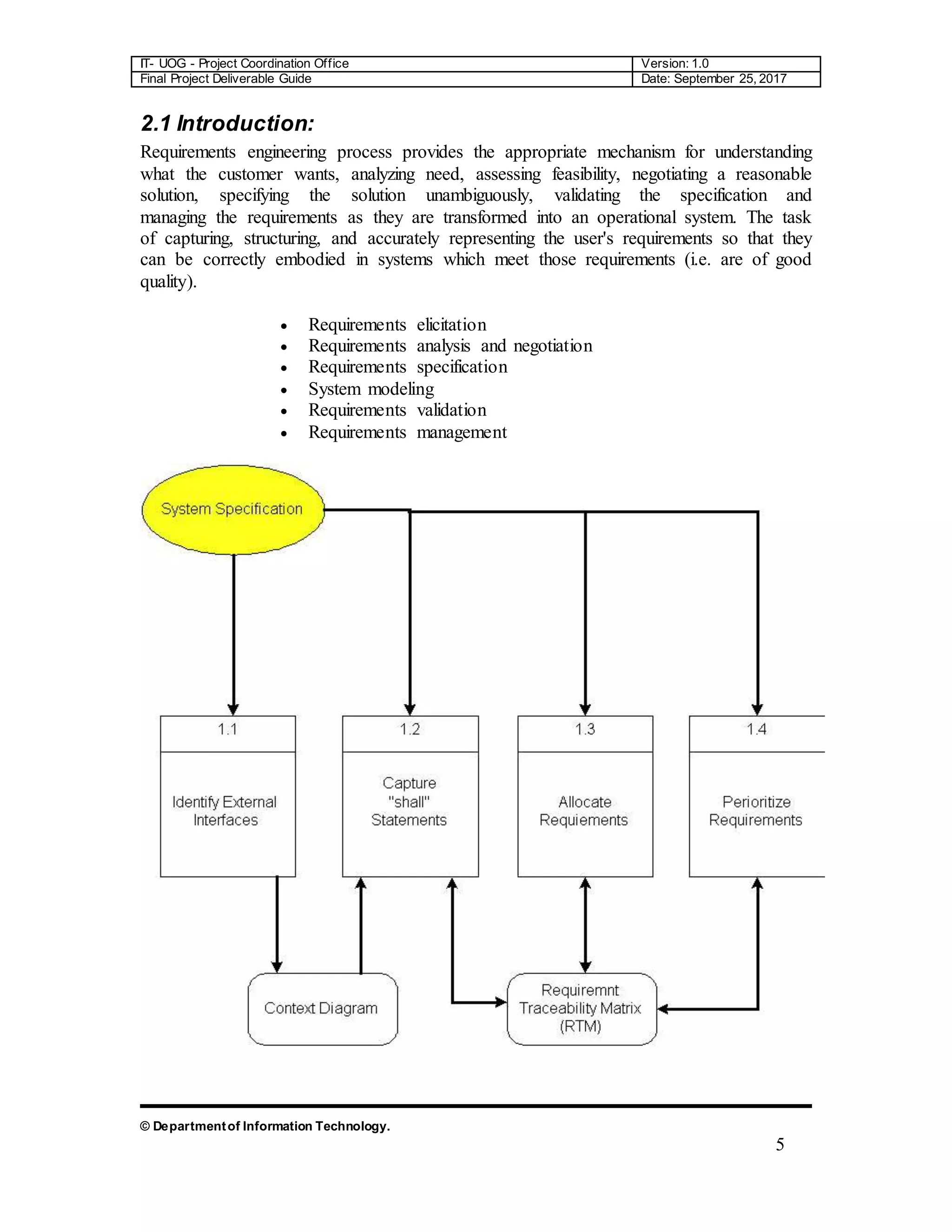
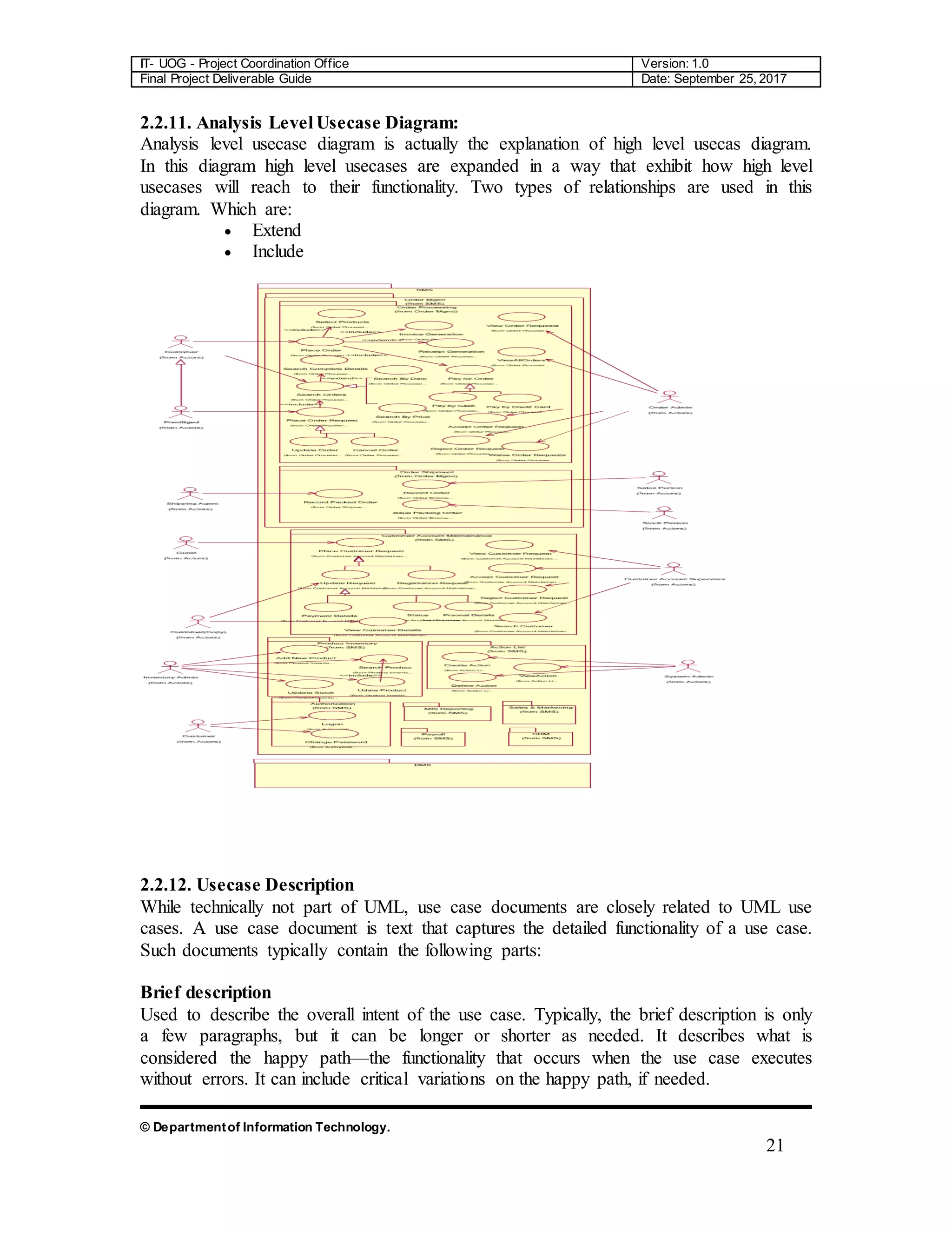
The document is a comprehensive final project deliverable guide for the Department of Information Technology at the University of Gujrat, detailing the project coordination for an object-oriented approach. It covers system requirement specifications, identifying external entities, use case diagrams, and design documentation crucial for developing an automated system for the Green Wood Company, which manufactures and sells sports goods. The guide outlines requirements engineering processes and emphasizes accurate requirement capturing for enhancing operational efficiency.


![IT- UOG - Project Coordination Office Version: 1.0
Final Project Deliverable Guide Date: September 25, 2017
© Departmentof Information Technology.
27
Lifelines
Lifelines are vertical dashed lines that indicate the object's presence over time.
Destroying Objects
Objects can be terminated early using an arrow labeled "< < destroy > >" .
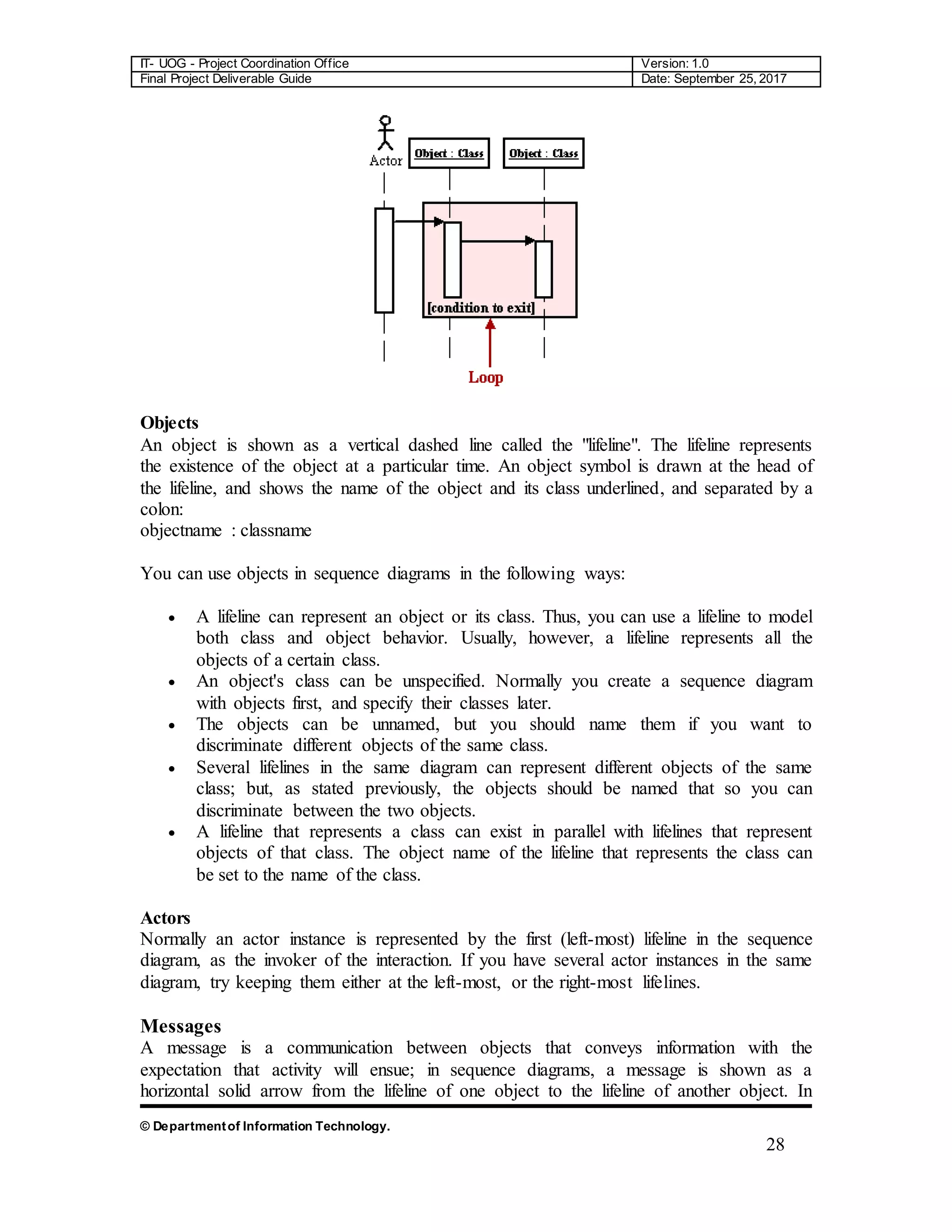
Loops
A repetition or loop within a sequence diagram is depicted as a rectangle. Place the
condition for exiting the loop at the bottom left corner in square brackets [ ].](https://image.slidesharecdn.com/32182-200209113518/75/University-of-Gujrat-Lahore-sub-Campus-Documentation-FYP-27-2048.jpg)


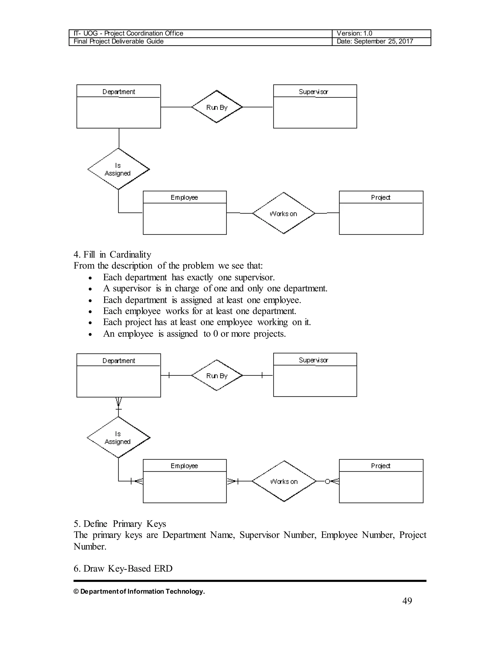
![IT- UOG - Project Coordination Office Version: 1.0
Final Project Deliverable Guide Date: September 25, 2017
© Departmentof Information Technology.
45
that Frame does not know anything about Window. Once again note the name on the
role. This relationship will almost certainly be implemented with a pointer of some kind.
What is the difference between an aggregation and an association? The difference is one
of implication. Aggregation denotes whole/part relationships whereas associations do not.
However, there is not likely to be much difference in the way that the two relationships
are implemented. That is, it would be very difficult to look at the code and determine
whether a particular relationship ought to be aggregation or association. For this reason, it
is pretty safe to ignore the aggregation relationship altogether. As the amigos said in the
UML 0.8 document: “...if you don’t understand [aggregation] don’t use it.” Aggregation
and Association both correspond to the Has-by-reference relationship from the Booch-94
notation.
Dependency
Sometimes the relationship between a two classes is very weak. They are not
implemented with member variables at all. Rather they might be implemented as member
function arguments. Consider, for example, the Draw function of the Shape class.
Suppose that this function takes an argument of type Drawing Context.
Figure shows a dashed arrow between the Shape class and the DrawingContext
class. This is the dependency relationship. In Booch94 this was called a ‘using’
relationship. This relationship simply means that Shape somehow depends upon
DrawingContext. In C++ this almost always results in a #include.
Interfaces
There are classes that have nothing but pure virtual functions. In Java such entities are not
classes at all; they are a special language element called an interface. UML has
followed the Java example and has created some special syntactic elements for such
entities. The primary icon for an interface is just like a class except that it has a special](https://image.slidesharecdn.com/32182-200209113518/75/University-of-Gujrat-Lahore-sub-Campus-Documentation-FYP-45-2048.jpg)