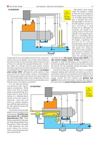
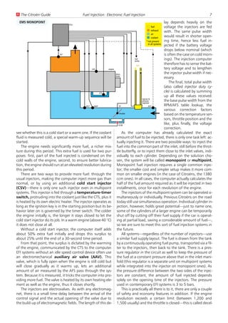
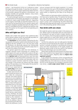
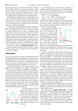
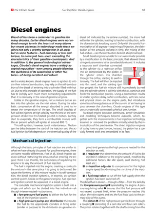
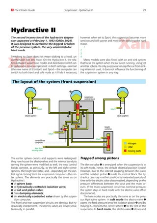
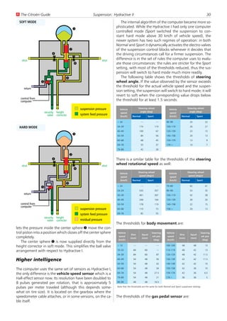
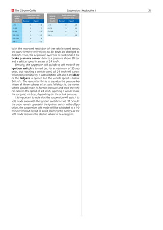
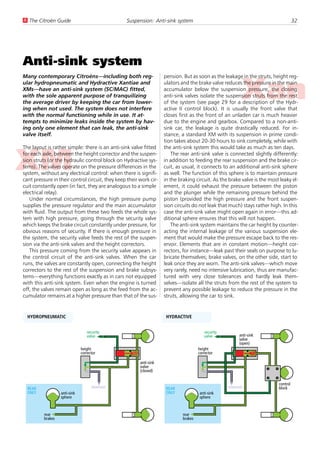
Željko Nastasic —
              ´
Gábor Deák Jahn


 The Citroën
 Technical Guide
There are many car manufacturers, makes, models
and versions on the road today but—as we all
know—none of them compares to Citroën in its
engineering excellence, especially regarding
suspension comfort, roadholding, and stability.

In this book we tried to describe how the various
subsystems work. We never intended to replace
service manuals or similar technical instructions.
Illustrations are schematic, focusing on the
principles of operation rather than on minute
details of implementation.

This guide is not linked to any specific Citroën
model but describes all systems and solutions
used on a large number of cars from the glorious
line of DS, ID, CX, GS, GSA, BX, XM, Xantia, Xsara
and the C5.
Table of Contents
Fuel Injection                                                                        Self-steering Rear . . . . . . . . . . . . . . . . . 42

  Electronic Fuel Injection . . . . . . . . . . . . . . . 5                          Brakes
  Diesel engines . . . . . . . . . . . . . . . . . . . 10
  Electronic Diesel Control . . . . . . . . . . . . . . 15                            Standard braking system. . . . . . . . . . . . . . 44
  Diesel Direct Injection . . . . . . . . . . . . . . . 17                            Anti-lock Braking System. . . . . . . . . . . . . . 45

Suspension                                                                           Electrical Systems
  A Suspension Primer . . . . .     .   .   .   .   .   .   .   .   .   .   .   19    Multiplex network . . . . . . . . . . . . . . . . . 47
  Hydropneumatic Suspension         .   .   .   .   .   .   .   .   .   .   .   20
  Hydractive I . . . . . . . . .    .   .   .   .   .   .   .   .   .   .   .   24   Air Conditioning
  Hydractive II . . . . . . . . .   .   .   .   .   .   .   .   .   .   .   .   29
  Anti-sink system . . . . . . .    .   .   .   .   .   .   .   .   .   .   .   32    Air conditioning . . . . . . . . . . . . . . . . . . 50
  Activa Suspension . . . . . .     .   .   .   .   .   .   .   .   .   .   .   33
  Hydractive 3. . . . . . . . .     .   .   .   .   .   .   .   .   .   .   .   35   Appendix
Steering                                                                              ORGA number . . . . . . . . . . . . . . . . . . 53

  Power Assisted Steering . . . . . . . . . . . . . . 38                             Index
  DIRAVI Steering . . . . . . . . . . . . . . . . . . 40
Fuel Injection
U The Citroën Guide                           Fuel Injection: Electronic Fuel Injection                                             5


Electronic Fuel Injection
The Otto engine needs a mixture of fuel and air                       up, the mixture can return to normal, but the temperature
for its operation. It would be the task of the fuel                   of the incoming air still plays a significant role: the cooler
supply—carburetor or injection—to provide the                         the air, the denser it becomes, and this influences the
engine with the ideal mixture. Unfortunately,                         lambda ratio as well.
there is no such thing as an ideal mixture.                              All these requirements are impossible to satisfy with sim-
                                                                      pler mechanical devices like carburetors. Electronic fuel in-
Perfect combustion, as chemistry calls it, would require air          jection provides a system that can measure the many cir-
and fuel in proportion of 14.7 parts to 1 (this is the                cumstances the engine is operating in and decide on the
stochiometric ratio). While this might be satisfactory for the        amount of fuel (in other words, the lambda ratio) entering
scientists, the real-life conditions of a vehicle call for slightly   the engine. By carefully adjusting the internal rules of this
different characteristics.                                            device, manufacturers can adapt the characteristic of the
    We use the ratio of actual mixture to the stochiometric           fuel injection to the actual requirements: a sporty GTi
mixture, called lambda (l), to describe the composition of            would demand rather different settings than a city car; be-
the mixture entering the engine: l=1 denotes the chemi-               sides, catalytic converters have their own demands that, as
cally ideal mixture, l<1 means rich, l>1 is lean.                     we will later see, upset the applecart quite vehemently.
    The best performance would require a slightly rich mix-              Earlier, fuel injection systems only knew about fuel, the
ture, with the lambda around 0.9, while fuel economy                  ignition was supplied by traditional methods. Later on,
would need a slightly lean one, between 1.1 and 1.3. Some             these systems (now called engine management systems)
harmful components in exhaust gas would reduce in quan-               took on the duty of generating the sparks as well. But even
tity between lambda values of 1 to 1.2, others below 0.8 or           with this second incarnation, the fuel injection part re-
above 1.4. And if this is not yet enough, a cold engine re-           mained practically the same, thus the following section ap-
quires a very rich mixture to keep running. After warming             plies to both kind of systems.


 Fuel injection
The two most important inputs describing the actual oper-                       Amount of fuel        Engine loadup, like the one il-
                                                                                  injected       0%   5%      …     100%
ating condition of the engine, thus determining the fuel de-                                                     lustrated here (of
mand are the engine speed (revolution) and engine                              idle       3    3      …      3
                                                                                                                 course, this is an il-
                                                                       Engine speed


load. The engine speed can be measured easily on systems                     850 rpm      4    5      …      5
                                                                                                                 lustration only, the
using traditional ignition: the ignition primary circuit gener-              900 rpm      5    6      …      7
                                                                                                                 actual values mean
ates pulses with their frequency proportional to engine                         …        …     …      …     …
                                                                                                                 nothing here), and
                                                                            6,000 rpm     9    8      …     10
speed (the tachometer uses this same signal to show the                                                          for any pair of in-
rpm to the driver). When the injection system provides the            coming engine speed and load values the necessary fuel
ignition as well, it cannot at the same time rely on it, so an        amount can be determined. By keeping the pressure of fuel
additional sensor is used instead.                                    constant behind the injector valves, the amount of fuel in-
    The engine load is usually determined by measuring the            jected depends solely on the time period the injectors are
quantity of air the engine tries to suck in. There are various        opened for, hence, the table can contain injector opening
methods of attaining this: earlier systems used a flap which          times.
is deflected by the air flowing through the sensor—the an-                An this is exactly how it is done in modern injection sys-
gle of deflection is proportional to the amount of air pass-          tems: the controlling microcomputer keeps a lookup table
ing through (air flow sensor, AFS). Later systems used a              like this to determine the base pulse width. Earlier systems
pressure sensor measuring the pressure inside the inlet man-          were constructed from discrete, analog elements, not like a
ifold (manifold absolute pressure, MAP sensor). Yet an-               small computer; a more or less equivalent circuit made of
other system (although not used on Citroëns) heats a plati-           various hybrid resistance arrays and semiconductors were
num wire and lets the incoming air passing around cool it;            used for the same purpose.
by measuring the current needed to keep the wire tempera-                 Chip tuning, by the way, is the simple operation of replac-
ture at a constant value above the temperature of the in-             ing the said table with another one, yielding different char-
coming air, the mass of air can be determined. Some sim-              acteristics (usually to gain power, allowing for worse fuel
pler systems do not even measure the amount of air but use            economy). As the computer stores this table in a program-
a pre-stored table in their computer to approximate it                mable memory—similar in function to the BIOS in desktop
based upon the engine speed and the position of the throt-            computers—, replacing it is possible. The earlier systems
tle pedal—not that accurate but certainly much cheaper.               with analog circuits cannot be modified that easily.
    Under ideal conditions, these two inputs would already                So, we obtained the base pulse width from the table but
be enough to control the engine. A large table can be set             as the operating conditions of automotive engines are
U The Citroën Guide                                         Fuel Injection: Electronic Fuel Injection                                                                           6
  EFI MONOPOINT                                                                                                                             Idle speed is more compli-
                                                ECU
                                                                                                                           fuel       cated: the throttle is closed,
                                                                                                                           exhaust
                                                                                                                                      so there has to be a bypass to
                                                                                                                           air
                                                                                                                           coolant
                                                                                                                                      let the engine receive fuel to
                                                                                                                      * not present   run. In simpler systems this by-
                                                                                                                        in all systems
                                                                                                                                      pass is constant (but manu-
                                                                                                                                      ally adjustable to set the cor-
                             OS*                                                                                                      rect idle speed) in a warm en-
                                                                                                    fuel
                                                                                                    pump
                                                                                                                                      gine, providing a fixed
                                                                                                      fuel
                                                                                                                                      amount of air, although the
                                                                        engine                                                        computer can decide on a
                                                                               distri-                                                varying amount of fuel to be
                                                                               butor
                                                                                                                                      injected. Later systems gener-
                                                                                                                                      ally use a controlling device
                                                                                                                                      changing the cross section of
                                                           CTS
                                                                                                                                      the bypass, regulating the
                                                                                                                                      amount of air coming
                                                                                                              injector &
                                                                                                              pressure                through (these systems often
                                                                                                              regulator
                                             ATS*      MAP                          TP                                ATS*            have no facility to adjust the
                                                                                                                                      idle speed, the computer
                                                                                    throttle
                                                                                                                                      knows the correct revolution
                                                                                                                                      and maintains it without any
                                                                                   ISCM
                                                                                                                                      help from mechanical de-
                                                                                                                                      vices). The controlling device
hardly ideal for any reasonable amount of time, several cor- can either be an idle speed control valve (ISCV) or an
rections have to be applied. Our air flow meter measures idle control stepper motor (ICSM). The first one can
the volume of the air but we would need to know the mass only open or close the idle bypass, so any regulation must
of the air to calculate the required lambda ratio—remem- be done by rapidly opening and closing it by the computer,
ber, colder air is denser, thus the same volume contains the second one can gradually change the bypass, hence
more gas, requiring more fuel to provide the same mixture. fine tuning is easier and smoother.
To accomplish this, the injection system uses an air temper-                            Just like the choke on carburetors, there is a complete
ature sensor (ATS)—although on some systems it mea- subsystem dealing with cold start and warm up, as the re-
sures not the air but the fuel-air mixture—and lengthens quirements under such circumstances are so different from
the injector pulse width according to this input (except for the normal operation that they cannot be fulfilled by the
the case of the airflow meter using a heated wire, this one regular control. The ECU monitors the ignition key
takes the air temperature into account automatically, conse- switch to learn when the engine is started, then looks for
quently, there is no need for correction).                                      the input from the coolant temperature sensor (CTS) to
    It is not only the external
circumstances that require EFI MULTIPOINT
                                                                                     ECU
special consideration. While                                                                                                                                            fuel
most of the time an engine                                                                                                                                              exhaust
works under partial load, so it                                                                                                                                         air
                                                                                                                                                                        coolant
makes sense to spare fuel by                                                                                                                                       * not present
basing on a relatively leaner                                                                                                                                        in all systems
mixture across this range of
operation, cold start and                                                OS*
warm-up, modest decelera-
tion and fully depressed throt-
tle, idle speed all require dif-                                                                                               engine
ferent treatment.                  fuel                                                                                                 distri-
    The position of the throttle pump                                                                                                   butor

pedal is communicated to the fuel
                                                              fuel rail
computer by a throttle posi-                                                          injectors
tion switch (TS) or throttle
                                                                                                                        CTS
potentiometer (TP). These                      pressure
                                               regulator
devices signal both fully open                                                                                             AAV
and fully closed (idling) throt-                                                                CSV*
                                                                                                                TS                                      AFS    ATS
tle positions. When the pedal
is fully depressed, the com-                                                                                      throttle

puter makes the mixture
richer to provide good acceler-
                                                                                                         idle speed                               idle mixture
ation performance.
U The Citroën Guide                         Fuel Injection: Electronic Fuel Injection                                                           7
  EMS MONOPOINT                                                                                                    lay depends heavily on the
                                   ECU
                                                                                                       fuel        voltage the injectors are fed
                                                                                                       exhaust
                                                                                                                   with. The same pulse width
                                                                                                       air
                                                                                                       coolant
                                                                                                                   would result in shorter open-
                                                                                                  * not present    ing time, hence less fuel in-
                                                                                                    in all systems
                                                                                                                   jected if the battery voltage
                                                                                                                   drops below nominal (which
                             OS*                                                                                   is often the case on cold morn-
                                                                                              fuel
                                                                                              pump
                                                                                                                   ings). The injection computer
                                                                                                fuel
                                                                                                                   therefore has to sense the bat-
                                                     CAS           engine                                          tery voltage and to lengthen
                                                                            distri-                                the injector pulse width if nec-
                                                                            butor
                                                                                                                   essary.
                                                                                                                       The final, total pulse width
                                                                                                                   (also called injector duty cy-
                                                             CTS
                                                                                                                   cle) is calculated by summing
                                                                                                                   up all these values received:
                                                                                                     injector &
                                                                                                     pressure      the base pulse width from the
                                                                                                     regulator
                                              ATS*     MAP                       TP                          ATS*  RPM/AFS table lookup, the
                                                                                                                   various correction factors
                                                                                 throttle
                                                                                                                   based on the temperature sen-
                                                                                                                   sors, throttle position and the
                                                                                ISCM
                                                                                                                   like, plus finally, the voltage
                                                                                                                   correction.
see whether this is a cold start or a warm one. If the coolant                      As the computer has already calculated the exact
fluid is measured cold, a special warm-up sequence will be                   amount of fuel to be injected, there is only one task left: ac-
started.                                                                     tually injecting it. There are two possible ways: to inject the
    The engine needs significantly more fuel, a richer mix-                  fuel into the common part of the inlet, still before the throt-
ture during this period. This extra fuel is used for two pur-                tle butterfly, or to inject them close to the inlet valves, indi-
poses: first, part of the fuel injected is condensed on the                  vidually to each cylinder. Depending on the solution cho-
cold walls of the engine, second, to ensure better lubrica-                  sen, the system will be called monopoint or multipoint.
tion, the engine should run at an elevated revolution during                 Monopoint fuel injection requires a single common injec-
this period.                                                                 tor; the smaller cost and simpler setup makes it more com-
    There are two ways to provide more fuel: through the                     mon on smaller engines (in the case of Citroëns, the 1380
usual injectors, making the computer inject more gas than                    ccm ones). In all cases, the computer actually calculates the
normal, or by using an additional cold start injector                        half of the fuel amount required as it will be injected in two
(CSV)—there is only one such injector even in multipoint                     installments, once for each revolution of the engine.
systems. This injector is fed through a temperature-timer                           The injectors of the multipoint system can be operated si-
switch, protruding into the coolant just like the CTS, plus it               multaneously or individually. Previous Citroëns on the road
is heated by its own electric heater. The injector operates as               today still use simultaneous operation. Individual cylinder in-
long as the ignition key is in the starting position but its be-             jection, however, holds great potential—just to name one,
havior later on is governed by the timer switch. The colder                  some of the cylinders of a larger engine can be temporarily
the engine initially is, the longer it stays closed to let the               shut off by cutting off their fuel supply if the car is operat-
cold start injector do its job. In a warm engine (above 40 °C)               ing at partial load, saving a considerable amount of fuel—,
it does not close at all.                                                    so we are sure to meet this sort of fuel injection systems in
    Without a cold start injector, the computer itself adds                  the future.
about 50% extra fuel initially and drops this surplus to                            All systems—regardless of the number of injectors—use
about 25% until the end of a 30-second time period.                          a similar fuel supply layout. The fuel is drawn from the tank
    From that point, the surplus is dictated by the warming                  by a continuously operating fuel pump, transported via a fil-
of the engine, communicated by the CTS to the computer.                      ter to the injectors, then back to the tank. There is a pres-
EFI systems without an idle speed control device often use                   sure regulator in the circuit as well to keep the pressure of
an electromechanical auxiliary air valve (AAV). This                         the fuel at a constant pressure above that in the inlet mani-
valve, which is fully open when the engine is still cold but                 fold (this regulator is a separate unit on multipoint systems
will close gradually as it warms up, lets an additional                      while integrated into the injector on monopoint ones). As
amount of air measured by the AFS pass through the sys-                      the pressure difference between the two sides of the injec-
tem. Because it is measured, it tricks the computer into pro-                tors are constant, the amount of fuel injected depends
viding more fuel. The valve is heated by its own heating ele-                solely on the opening time of the injectors. The pressure
ment as well as the engine, thus it closes shortly.                          used in contemporary EFI systems is 3 to 5 bars.
    The injectors are electrovalves. As with any electromag-                        This is practically all there is to it, there are only a couple
net, there is a small time delay between the arrival of the                  of safety and economy features in addition. If the engine
control signal and the actual opening of the valve due to                    revolution exceeds a certain limit (between 1,200 and
the build-up of electromagnetic fields. The length of this de-               1,500 usually) and the throttle is closed—this is called decel-
U The Citroën Guide                             Fuel Injection: Electronic Fuel Injection                                                                                 8
eration—, the momentum of the car is sufficient to rotate                vacuum increases with the engine revolution, its sucking
the engine through the wheels. To save fuel, the injection is            force rotates the inner part of the distributor slightly away
cut off. As soon as the engine speed drops below the limit               from its original position, causing all its timing devices
or the throttle is opened, the injection is reintroduced—sup-            switch earlier, as required by the value of the timing ad-
posedly smoothly and gradually, however, many drivers                    vance.
complain about some jerkiness.                                              Clever systems can get away without a distributor: some
   To avoid prolonged operation at revolutions exceeding                 CXs have such an ignition setup. This systems has two igni-
the specification of the engine, the injection is cut off above          tion coils, both serving two spark plugs at the same time.
a maximum engine speed (6,000-7,000 rpm, depending                       These two spark plugs belong to cylinders whose pistons
on the engine). And finally, to avoid the hazard of fire in a            move in unison: one is compressing, the other exhausting.
crash and the fuel squirting from the injection system with              Although both plugs generate sparks at the same time, the
the engine stopped or possibly destroyed, the relay of the in-           one in the exhausting cylinder will be wasted.
jectors is controlled by the ECU, allowing fuel injection only
when the ignition (or the signal of the corresponding sen-               Two birds with one stone
sor) is present.
                                                                         We made the ignition seem too simple in the previous sec-
Who will light our fire?                                                 tion. While it works as described, there are many factors to
                                                                         be considered if we want to build a modern ignition sys-
Models with simpler fuel injection have traditional (elec-               tem. For instance, the timing advance depends not only on
tronic) ignition systems which are practically equivalent to             engine speed but on many other factors as well: engine
the solution used on cars with carburetors.                              load, engine temperature and to some extent, the air tem-
   The distributor has two purposes: generating the driv-                perature.
ing signal for the ignition system and to distribute the high               Just like the carburetor was not really good at deciding
voltage to the four cylinders in turn. This two parts inside             the amount of fuel required by the engine, the traditional
the distributor are electrically separate but mechanically               ignition is similarly not perfect in estimating the timing ad-
coupled—both are driven by the camshaft to keep them in                  vance and other characteristics of the sparks needed. An
sync with the strokes of the engine.                                     electronic system similar to the one used for fuel injection
   The ignition signal thus starts from the distributor. A               shows clear advantages over any earlier system.
magnetic induction sensor (consisting of a rotating four-                   And as they use about the same sensors and rely on each
sided magnet and a pick-up coil) sends a pulse to the igni-              other, what could be more logical than to integrate them
tion module at each firing point. This pulse will be switched            into a common system, elegantly called an engine man-
to the ignition coil (an autotransformer; auto here does                 agement system?
not mean that it is manufactured for automotive use, auto-                  If we compare the schematics of the corresponding EFI
transformers have their primary and secondary coils con-                 and EMS systems, they look almost the same. There are two
nected) by a power transistor inside the module. The cur-                notable differences: the small arrow on the line connecting
rent change in the primary coil induces very high voltage                the ECU to the distributor has changed its direction and a
spikes in the secondary circuit. These spikes then go back to            new sensor, a crank angle sensor (CAS) has appeared.
the HT part of the distributor
which in turn sends them to EMS MULTIPOINT
                                                                          ECU
the spark plug of the actual                                                                                                                                     fuel
                                                                                       CO pot
cylinder requiring the spark.                                                                                                                                    exhaust
   It takes some time for the                                                                                                                                    air
                                                                                                                                                                 coolant
spark to ignite the fuel-air mix-                                                                                                                           * not present
ture inside the combustion                                                                                                                                    in all systems
chamber: this means that the
spark has to arrive slightly be-                                   OS*
fore the piston reaches its top
position (top dead center,
TDC), so that it will receive the                                                               CAS      KS         engine
downward force of the deto- fuel
                                                                                                                             distri-
nation in the right moment. pump                                                                                             butor

However, as the engine speed fuel
                                                         fuel rail
increases, so does the speed                                               injectors
of the piston or the distance it
                                                                                                          CTS
travels during a given period                  pressure
                                               regulator
of time. Therefore, the exact                                                                                 AAV
time of the spark has to be ad-                                                                  TS                                         AFS       ATS
vanced as the revolution in-
creases. Traditional systems                                                                      throttle

do this by adding a vacuum
line connecting the inlet mani-
                                                                                                  ISCV                                 idle mixture
fold to the distributor. As the
U The Citroën Guide                         Fuel Injection: Electronic Fuel Injection                                           9
Both changes have to do with the fact that the enhanced                By using platinum (Pt) or rhodium (Rh) as a catalyst—a
system, whose new task is to generate the ignition signals         catalyst is a substance whose presence is required to enable
as well, cannot at the same time build on them as inputs.          (or to boost) a chemical transformation while it does not
This new sensor—practically a replacement for the induc-           take part in the process itself, remaining intact—the follow-
tion magnet in the distributor of earlier systems—informs          ing processes can be carried out:
the computer of both engine speed and camshaft position.               2 CO + O2 W 2 CO2 (oxidation)
   The flywheel has steel pins set into its periphery. As it ro-       2 C2H6 + 7 O2 W 4 CO2 + 6 H2O (oxidation)
tates, the inductive magnet of the CAS sends pulses to the             2 NO + 2 CO W N2 + 2 CO2 (reduction)
computer. Two of the pins are missing and this hole passes         These precious metals are applied in a very thin layer to the
before the sensor just as the first piston reaches its TDC posi-   surface of a porous ceramic body with thousands of holes
tion. The missing pins cause a variance in the sensor output       to make the surface contacting the exhaust gases much
that can be read by the ECU easily.                                greater. Actually, a converter does not contain more than 2
   The rest is the same: the base pulse width is calculated        or 3 gramms of these metals.
based on the CAS and AFS/MAP sensors. The correction fac-              If you compare this diagram         %
tors—air temperature, idle or full load, starting, warming         with the previous one, you will                             NO
                                                                                                                               x

up, battery voltage—sum up into an additional pulse                see that the real gain is the
width. Besides, the same input signals (AFS, CAS, CTS and          supression of nitrogen-oxides.           CO

TS/TP) are used for another lookup in a table, yielding the        CO and CmHn will be reduced as
correct dwell time and timing advance for the ignition. The        well, although to a much lesser
dwell period remains practically constant but the duty cycle       extent. Nevertheless, the overall       CH
                                                                                                           n   m


varies with the chaging engine speed. The ignition signal is       reduction in polluting byprod-
amplified and sent to a distributor containing only second-        ucts is quite high, amounting
ary HT components: it does not create the ignition signal          up to 90 percent. Lead sub- 0.9               0.99 1.0   1.1 V

only routes the HT current to each spark plug in firing order.     stances are not considered as
   Some systems also have a knock sensor (KS), sensing             lead must not reach the converter anyway, it would clog the
the engine vibration associated with pre-ignition (so-called       fine pores of the converter in no time. The fuel used in cars
pinking). If this occurs, the ignition timing is retarded to       equipped with a catalytic converter has to be completely
avoid engine damage.                                               free of lead.
                                                                       But there is something of even greater consequence de-
Think green                                                        picted on the diagram: to keep the amount of pollutants
                                                                   down, the lambda has to be kept inside a very small value
As we saw, fuel injection and engine management systems            range, practically at l=1 all the time. If the lambda drops
are capable of determining the ideal amount of fuel to be in-      just a fraction below 1, the CO emission rises sharply, while
jected, depending on the conditions of operation and sev-          a small step above 1 skyrockets the NOx emission. The main
eral other factors in the engine. It is capable of deciding on     task of the fuel injection is therefore to ensure that the air-
lean mixture for general, partial load to save fuel, or on rich    fuel mixture sticks to the stochiometric ratio all the time.
mixture when performance considerations call for this.             This means higher consumption than the one of a car with
    Unfortunately, this is not what such systems are used for      fuel injection without a converter to start with.
today. With the proliferation of catalytic converters, the             There are situations where this lambda cannot be ob-
only concern of our systems is the welfare of the converter.       served. A cold engine will simply stall without a much richer
    Ideal combustion would not generate polluting materi-          mixture, thus the cold start mechanism does not obey the
als in the exhaust gas. Fuel is a mixture of various hydrocar-     lambda control. The catalytic converter does not work at all
bons (CnHm), which when burned together with the oxygen            below 250 °C, so this is not a significant compromise (its
(O2) of the air, should transform to carbon-dioxide (CO2)          normal operating temperature is 400 to 800 °C, above
and water vapor (H2O). However, combustion is never ideal,         800 °C is already harmful; unburned fuel getting into the ex-
besides, fuel contains many additives: the exhaust gas, in         haust and detonating inside the converter could cause over-
addition to the products mentioned, has various byprod-            heating, thus ignition and similar problems has to be recti-
ucts as well, some of them toxic: carbon-monoxide (CO),            fied as soon as possible in catalytic cars).
various unburned hydrocarbons (CnHm), nitrogen-oxides                  Dynamic acceleration (full throttle) is also something not
(NOx) and lead (Pb) in various substances coming from the          observing the welfare of the converter. Reducing pollution
anti-knock additives found in the fuel.                            might be a noble cause but to be able to end an overtaking
                                The relative amount of these       is even more important…
    %                        byproducts depend on the                  The system uses an oxygen sensor (OS, also called
                             lambda ratio of the air-fuel mix-     lambda sensor) which measures the oxygen content of the
                NO
                x
                             ture burned. As shown on the di-      exhaust gas. It is located between the engine exhaust and
                             agram, a value between 1.2 and        the catalytic converter. Similarly to the converter, it is not
      CH
                             1.3 would give a relatively low       functional below 300 °C, hence it has its own heating ele-
    n   m
                             percentage of toxic byproducts        ment to make it reach its operating temperature faster.
     CO                      while, as we can recall, being a          The computer uses the input from this sensor to keep the
                             lean mixture would be in the          mixture injected always as close to l=1 as possible. If the
                             right direction towards fuel          sensor is still too cold to give accurate input, the computer
  0.8       1.0    1.2 1.3 V economy.                              can ignore it safely.
U The Citroën Guide                              Fuel Injection: Diesel engines                                              10


Diesel engines
Diesel oil has been a contender to gasoline for                    diesel oil, indicated by the cetane number), the more fuel
many decades. Earlier diesel engines were not re-                  will enter the cylinder, leading to harsher combustion, with
fined enough to win the hearts of many drivers                     the characteristic knocking sound. Only with the careful har-
but recent advances in technology made these en-                   monization of all aspects—beginning of injection, the distri-
gines not only a worthy competitor in all areas                    bution of the amount injected in time, the mixing of the
but in some features—fuel economy or low end                       fuel and air—can the combustion be kept at optimal level.
torque, to name just two—even exceeding the                            Small diesel engines suitable for cars were made possible
characteristics of their gasoline counterparts. And                by a modification to the basic principle, that allowed these
in addition to the general technological advan-                    stringent parameters to be considerably relaxed. It includes
tages, Citroën’s diesel engines have a widely ac-                  a separate swirl chamber connected
cepted reputation—even among people blaming                        to the cylinder via a restrictor orifice.
the quirkiness of its suspension or other fea-                     The air compressed by the piston in
tures—of being excellent and robust.                               the cylinder enters this chamber
                                                                   through the orifice, starting to swirl in-
As it is widely known, diesel engines have no ignition to initi-   tensively. The fuel will then be injected
ate their internal combustion, they rely on the self-combus-       into this swirl, and the starting igni-
tion of the diesel oil entering into a cylinder filled with hot    tion propels the fuel-air mixture still incompletely burned
air. Due to this principle of operation, the supply of the fuel    into the cylinder where it will mix with the air, continue and
has to comply with much more demanding requirements                finish the combustion process. Using a prechamber results
than it is necessary in the case of gasoline engines.              in smaller ignition delay, softer combustion, with less noise
    Unlike in the gasoline engine, not a mixture but air en-       and physical strain on the engine parts, but introduces
ters into the cylinders via the inlet valves. During the adia-     some loss of energy because of the current of air having to
batic compression all the energy absorbed is used to in-           pass between the chambers. Citroën engines of this type
crease the temperature of the gas. The small droplets of           use a tangentially connected spherical prechamber.
fuel will be injected at high velocity near the end of the com-        As diesel engine evolution continued, better simulation
pression stroke into this heated gas still in motion. As they      and modeling techniques became available, which, to-
start to evaporate, they form a combustible mixture with           gether with the improvements in fuel injection technology,
the air present which self-ignites at around 800 °C.               lessened or removed the problems initially solved by the in-
    This self-ignition, however, is not instantaneous. The lon-    troduction of the prechamber. The direct injection engines
ger the delay between the start of the injection and the ac-       of today have no prechamber, instead, the piston has a spe-
tual ignition (which depends on the chemical quality of the        cially formed swirl area embedded in its face.


 Mechanical injection
Although the basic principles of fuel injection are similar to           gines) and generates the high pressure needed for the
what we have already discussed for gasoline engines, there               injection as well;
are some notable differences. First of all, diesel engines op-        U a regulator that determines the amount of fuel to be
erate without restricting the amount of air entering the en-             injected in relation to the engine speed, modified by
gine: there is no throttle, the only means of regulating the             additional factors like idle speed, cold starting, full
engine is to vary the amount of fuel injected.                           load, etc.;
   The fuel is injected into the engine, creating a combusti-         U an injection adjuster to compensate for the higher
ble mixture in the same place it is going to be burned. Be-              engine speed by advancing the start time of the injec-
cause the forming of this mixture results in its self-combus-            tion;
tion, the diesel injection system is, in essence, an ignition         U a fuel stop valve to cut off the fuel supply when the
control system. Unlike on the gasoline engine, fuel injection            ignition has been switched off.
and ignition cannot be separated in a diesel engine.               The diesel fuel is drawn—through a filter—from the tank by
   The complete mechanical injection system is built into a        the low pressure pump 1 operated by the engine. A pres-
single unit which can be divided into five individual—al-          sure regulating valve 2 ensures that the fuel pressure will
though interconnected—subsystems:                                  not exceed a preset limit; when the pressure reaches this
   U a low pressure fuel pump to deliver the fuel for the          value, the valve opens and lets the fuel flow back to the pri-
      rest of the injection system;                                mary side of the pump.
   U a high pressure pump and distributor that routes                 The piston 6 of the high pressure part is driven through
      the fuel to the appropriate cylinders in firing order        a coupling 4 consisting of a cam disc and four cam rollers.
      (similar in purpose to the distributor on gasoline en-       The piston rotates together with the shaft coming from the
U The Citroën Guide                                      Fuel Injection: Diesel engines                                                                  11
                                                                                     ß
      fuel from/to tank                                                       full             idle                                          accelelator
                                                                                                                                             pedal
      low pressure                                        regulator
      high pressure                                                                               Ý            Þ
      adjusting screws
                                                                                                               9       fuel
                                                                                          å                            to tank
                                                                                                       Ü
                            fuel                                                                  á                              fuel stop
                                                                          8                   æ
                                                                                                                                     valve

                                   2         fuel pump                                                             ã
                                                          3
                                                                                                                        â                     ignition
                                                                                                                                               switch
                                                 1                                                             Û
                                                                                 4
 engine
                                                                                                                                                   6
                                                                                                                                   6

                                                                                                                       ä
                                                                                                           5                      7

                                                                                                                                             injectors
                  injection                                           à                  high pressure pump
                  adjuster                                                               and distributor


engine but the coupling adds a horizontal, alternating                             As the piston 6 moves to the right, at some point the
movement as well: for each turn, the shaft and the piston 6                    side outlets will emerge from under the regulator col-
performs four push-pull cycles.                                                lar 5—the fuel injection into the real output will stop imme-
    It is the pushing movement of this piston 6 that creates                   diately, and the rest of the fuel stored in the chamber will
the high pressure and sends the fuel to the injectors. The                     leave through this path of lesser resistance. This is phase 4,
fuel, provided by the pump 1 arrives through the fuel stop                     the end of the injection cycle.
electro-valve â, which is constantly open while the ignition                       Actually, this operation is repeated four times for each
switch is on but cuts the fuel path when it is turned off.                     revolution of the incoming shaft. There are four high pres-
    First, the piston 6 is pulled back by the coupling 4,                      sure outlets radially around the piston, each serving a given
letting the fuel enter the chamber and the longitudinal bore                   cylinder. As the outlet slot ä of the piston turns around, it al-
inside the piston. As the side outlets are blocked by the regu-                lows only one of the outlets to receive the fuel.
lator collar 5, the fuel stays inside the chamber (phase 1).                       The pressure valves 7 serve to drop the pressure in the in-
    In the next phase, the piston rotates and closes the in-                   jector lines once the injection cycle is over. To reduce the cav-
gress of fuel from the stop valve â. On the other side of the                  itation caused by the pressure waves generated by the rapid
piston, the high pressure outlet opens but as the fuel is not                  closing of the injector valves, a ball valve minimizing the
yet under pressure, it will stay in the chamber.                               back flow is also used.
    In phase 3 the piston is energetically pushed by the cam                       The length of phase 3, thus the amount of fuel injected
disc and rollers of the coupling 4, injecting the fuel stored                  depends on the position of the collar 5. If it is pushed to the
in the chamber into the output line with a significant force.                  right, it will cover the side outlets for a longer time, result-
                                                                               ing in a longer injection phase, and vice versa. If it stays in
  PHASE 1                              PHASE 2                                 the leftmost position, no fuel will be injected at all.
                                                                                   And this is exactly what the regulator part does: it
                                                                               moves this collar 5 to the left and to the right, as the actual
    5                                   5                                      requirements dictate. The lever 9 attached to the collar is ro-
                            6                             6
                                                                               tated around its pivot by several contributing forces. The
                                                                               two main inputs are the position of the accelerator pedal
                                                                               as communicated through a regulator spring Ý and the ac-
                                                                               tual engine speed, driving a centrifugal device 8 via a pair
                                                                               of gears 3. The higher the engine speed, the more the
  PHASE 3                              PHASE 4                                 shaft å protrudes to the right, pushing on the lever Û.
                                                                                   When the engine is being started, the centrifugal device
                                                                               8 and the shaft å are in their neutral position. The starting
    5                                   5                                      lever Û—pushed into its starting position by a spring Ü—
                            6                             6
                                                                               sets the position of the collar 5 to supply the amount of
                                                                               fuel needed for the starting.
                                                                                   As the engine starts to rotate, a relatively low speed will
                 injector                                                      already generate a large enough force in the centrifugal de-
                                                                               vice 8 to push the shaft å and overcome the force of the
U The Citroën Guide                                      Fuel Injection: Diesel engines                                                   12

  STARTING                              IDLE SPEED                           The excess fuel will finally leave the pump unit through
            pedal                                pedal
                                                                          an overflow valve ã, flowing back to the fuel tank.
    ß                                    ß
                                    9                                 9   Something needs to be corrected…
                        Ý           Þ                    Ý            Þ   The chemistry involved in the combustion dictates some pa-
                                                                          rameters of fuel injection, the most important being the
                                                                          smoke limit, the maximum amount of fuel injected into a
                    å                                    å                given amount of air, that results in combustion without re-
                            Ü                                    Ü        sulting in soot particles. Although gasoline engines also
        8                                                                 have this limit, they normally operate with a constant fuel
                                             8
                        Û                                    Û            to air mixture that automatically places the amount of fuel
                                                                          below this critical limit. Diesel engines, in contrast, operate
                                                                          with a variable fuel to air mixture, using this very variation
                                5                                 5       for power regulation. With diesel fuel observing the smoke
                                                                          limit is a much stricter task because once soot starts to de-
                            6                                    6
                                                                          velop, this changes the character of the combustion itself,
                                                                          resulting in a sudden and huge increase in the amount of
rather weak spring Ü. This will rotate the lever Û, moving                particulates—a bit like a chain reaction.
the collar 5 to the left, setting the amount of fuel required                 Because the maximum amount of fuel injected depends
for idling. The accelerator pedal is in the idle position as              on how far the lever Û is allowed to rotate counter-clock-
well, dictated by the adjustment screw ß. The idle spring Þ               wise, the inability of the pump to inject too much fuel,
keeps the regulator in equilibrium.                                       thereby crossing the smoke limit, is insured by an end stop
    Normally, the amount of                                               æ for this lever. This very basic means of smoke limit correc-
fuel will be regulated by the DECREASE/INCREASE                           tion, adjusted for worst case conditions, was developed fur-
position of the pedal as both               pedal                         ther on turbocharged engines, and still further on electroni-
springs Ü and Þ are fully             ß                                   cally controlled injection systems.
compressed and do not take                                  9                 Timing is of enormous importance in a diesel engine.
an active part in the process.                                            During the stroke of combustion, several events take place
                                                   Ý         Þ
When the driver pushes on                                                 in close succession: the fuel injection system starts its deliv-
the pedal, the regulating                                                 ery, then the fuel is actually injected (the time elapsed be-
spring Ý stretches, both le-                                              tween these two is the injection delay), slightly later the fuel
                                                  å
vers 9 and Û rotate and                                                   will self-ignite (this delay is the ignition delay), then the injec-
                                                        Ü
move the collar 5 to the                                                  tion will stop but the combustion is still raging, first reach-
right, to allow the maximum              8                                ing its maximum, then dying away slowly (on the scale of
                                                     Û
amount of fuel to be in-                                                  milliseconds, that is).
jected. As the actual engine                                                  Just like in a gasoline engine, the ignition delay remains
speed catches up, the centrif-                                            constant while the engine speed changes. The fuel has to ig-
ugal device 8 opens up,                                  5                nite before the piston passes its TDC position, but with the
pushing the shaft å to the                              6                 increasing engine speed, the distance the piston travels dur-
right, countering the previ-                                              ing a given period of time becomes longer. Therefore, the in-
ous force, gradually return-                                              jection has to be advanced in time to catch the piston still in
ing the collar 5 towards the no fuel position, until the point            time. The injection adjuster à feeds on the fuel pressure
is reached where the amount of fuel injected maintains the                provided by the pump 1, proportional to the engine speed.
equilibrium. When the driver releases the pedal, the inverse                  This will move the piston, which in turn, through the le-
of this process takes place. During deceleration—pedal at                 vers, modifies the relative position of the cam rollers to the
idle, engine rotated by the momentum of the car—the fuel                  cam disc inside the coupling 4, increasing or decreasing
is cut off completely.                                                    the phase difference between the revolutions of the engine
    Without such regulation, if enough fuel is provided to                and the rotating-alternating movement of the distributor
overcome the engine load, it would continue accelerating                  piston 6.
until self-destruction (this is called engine runaway). Speed                 Some engines also have additional minor correction
regulation is a feedback mechanism comparing the actual                   mechanisms á that modify the idle speed and timing de-
speed of the engine to the one dictated by the gas pedal                  pending on engine temperature, to provide better cold
and modifies the amount of fuel as necessary. If either the               start performance. The engine temperature is measured in-
engine speed changes (because of varying load, going over                 directly, through the coolant acting on cylinder and piston-
a hill, for instance) or the driver modifies the position of the          like elements filled with paraffin. As the paraffin expands or
accelerator pedal, the regulation kicks in, adding more or                contracts as the coolant temperature dictates, the trans-
less fuel, until a new equilibrium is reached. If the engine is           formed mechanical movement, coupled through cables to
powerful enough to cope with the load, keeping the pedal                  two movable end stops for both the lever 9 and the injec-
in a constant position means constant cruising speed in a                 tion adjuster à, modifies the idle speed and the injection
diesel car; gasoline vehicles need speed regulated fly-by-                timing of the engine. Because correct timing depends on
wire systems or cruise controls to achieve the same.                      temperature, the corrections, although relatively slight, in-
U The Citroën Guide                                Fuel Injection: Diesel engines                                               13
sure that the amount of fuel injected as well as the timing          increase in engine speed, the rotational speed of the tur-
provide better combustion and lower pollution when the               bine (note the quadratic relationship) would become exces-
engine is started and operated at low temperatures. They             sively high. When the turbine blade speed approaches the
do not have any effect once the engine reaches the normal            speed of sound, a supersonic wave effect occurs that can
operating temperature.                                               abruptly leave it without any load, at which point runaway
                      Now that the correct amount of fuel is care-   would occur, resulting in severe damage to the turbine.
   HP fuel        fully determined and the necessary high pres-          On the other hand, if the turbine was dimensioned so
           return
                  sure generated by the pump, it has to be in-       that even at the highest engine speed it is still operating
     1            jected into the swirl chamber. The pressurized     within safe limits, it would not be useful at all in the middle
                  fuel entering the injector through a filter 1      range where the engine is most often used. A compromise
        3         tries to press the piston 2 upwards but a          can be achieved using an overpressure valve, the waste-
                  spring 3 counters this force. As soon as the       gate valve 5. The turbo pressure is constantly monitored
            2     pressure exceeds the force of the spring           by this valve opening above a set pressure limit, letting the
                  (which can be adjusted by placing appropri-        exhaust escape through a bypass. This avoids turbo run-
                  ately sized shims behind it), the piston jumps     away by making the turbo rotational speed proportional to
                  up and the fuel rushes into the swirl chamber      that of the engine, once the limit pressure is reached. This
through the small orifice now opened. After the injection            way the quick spin-up resulting from the quadratic relation-
pump closes its pressure valve at the end of the injection pe-       ship can be preserved while the turbocharging effect is ex-
riod, the spring 3 pushes the piston 2 back, closing the ori-        tended over a significant percentage of the usable engine
fice until the next injection cycle.                                 speed range—typically the higher 70-80%. But it comes at
    Each swirl chamber has its own glow plug whose only              a price: because of the simplicity of such a regulation, the
purpose is to heat up the chamber in cold weather. They              limit pressure is dictated by the maximum turbine speed,
start to glow when the ignition key is turned into the first         which is usually calculated for maximum engine speed plus
position and stay glowing for some time afterwards unless            a safety margin. The maximum pressure is already reached
the starting was unsuccessful.                                       at lower engine and turbine speeds, where the turbine
                                                                     could conceivably still provide more pressure because of a
Turbo                                                                lesser demand for air volume. Although with a simple
                                                                     wastegate a certain amount of the turbocharging potential
More power requires                                                  is lost, the increase in power output is still substantial.
more fuel. An efficient                       4                          Citroën is a pioneer in implementing variable wastegate
way to boost the perfor-                                             limit pressure using a controllable wastegate valve, to tap
                                                              5
mance is to provide                                                  into this previously unused turbo potential.
                                        2
both more air and fuel                         3                         Essentially, a turbocharged diesel engine runs in two dif-
to the engine. The ex-                                               ferent modes: atmospheric pressure or turbo-charged. The
haust gases rushing out                                              atmospheric pressure mode prevails while the exhaust gas
                                                          air
from the engine waste                                                produced is not yet sufficient to power the turbine (below a
                                       1                  exhaust
a great deal of energy; a                                            given engine speed and load). Once this limit is crossed and
turbocharger 4 spun                                                  the turbine starts generating higher than atmospheric pres-
by the exhaust flow taps into this source of energy to pro-          sure, the engine is running in turbocharged mode.
vide added pressure in the air inlet. Diesel engines are partic-                                        The injection pump regula-
ularly well suited for turbocharging. Gasoline engines may                                          tor needs to know about the
                                                                                turbo
not have the inlet pressure raised too much because the air                     pressure            changes in the inlet pressure,
and fuel mixture may subsequently self-ignite when it is not                                    æ because those changes mean
supposed to, and instead of burning controllably, detonate.               pedal       ç             differences in the amount of
In a diesel such a situation is not possible because the fuel is      ß                             air entering the engine. And
injected only when combustion should actually happen in                                      9      this also means that the upper
the first place. As a result, relatively high inlet pressures can                                   limit of fuel injected needs to
                                                                                              Þ
be used, considerably improving the power output of a die-                                          be changed correspondingly.
sel engine, and with proper attention to the subtleties of                         Ý                These injection systems are
the design, engine efficiency and fuel consumption.                                                 tuned for the turbo producing
   On its own, once the amount and pressure in the ex-                                              the rated waste pressure (also
haust manifold reaches a level high enough to power it,                                             known as full boost). How-
with the engine fully loaded, the turbine would spin propor-         ever, the amount of fuel injected during the atmospheric
tionally to engine speed squared, because both the pres-             mode of the engine—before the turbo kicks in—has to be
sure and the volume of the air pumped into the engine are            reduced in order to avoid crossing the smoke limit. The
increasing.                                                          turbo pressure drives a limiter in the injection pump: with
   Because the engine is required to deliver as much torque          the increasing pressure the piston æ moves down. Its vary-
as possible at the widest possible range of engine revolu-           ing diameter forces the lever ç rotate around its pivot,
tion, the requirements on the turbine are somewhat contra-           which then acts as a stop to limit the allowed range of oper-
dictory. If the turbo is made very small and light, it will spin     ation of the regulator lever 9, limiting the amount of fuel to
up very quickly due to its low mass and inertia, ensuring its        be injected.
full benefit already at low rpms. However, with a moderate               Intercooler
U The Citroën Guide                            Fuel Injection: Diesel engines   14
Towards a cleaner world

Exhaust Gas Recycling (EGR) systems were used—depend-
ing on the market—as add-on units. An electronic unit mea-
suring the coolant temperature and the position of the gas
pedal control on the pump (with a potentiometer fitted to
the top of the control lever) controls a valve which lets part
of the exhaust gas get back into the inlet.
    Post-glowing is also used as a pollution reducing mecha-
nism. A definite post-glow phase, lasting for up to minutes
is usually controlled by a combination of a timer and the en-
gine coolant temperature: either the timeout of 4 minutes
runs out or the engine reaches 50 °C. An additional mecha-
nism prevents post-glowing if the engine was not actually
started.
U The Citroën Guide                                  Fuel Injection: Diesel engines                                                                     15

 Electronic Diesel Control
Just like it is the case with gasoline engines and carburetors,         stances and conditions in and around the engine (air, en-
a mechanical device—even one as complicated as a diesel                 gine and fuel temperatures), the injection system can
injection pump—cannot match the versatility and sensibil-               achieve better characteristics, lower fuel consumption and
ity of a microcomputer coupled with various sensors, apply-             less pollution.
ing sophisticated rules to regulate the whole process of fuel               All in all, the electronically controlled injection pump not
injection.                                                              only adds precision to the injection process as its gasoline
    The only input a mechanical pump can measure is the en-             counterpart does but introduces completely new methods
gine speed. The amount of air entering into the engine, un-             of regulation; therefore it represents a much larger leap for-
fortunately, is far from being proportional to engine speed,            wards than fuel injection in gasoline engines. In spite of
and the turbo or the intercooler disturbs this relationship             this, it is quite similar to its mechanical predecessor. From
even further. As the injection always has to inject less fuel           the five subparts, four remain practically the same, only the
than the amount which would already generate smoke, the                 regulator is replaced with a simple electromagnetic actua-
mechanical pump—capable only of a crude approximation                   tor that changes the position of the same regulator collar 5
of what is actually going on in the engine—wastes a signifi-            as in the mechanical pump, in order to regulate the amount
cant amount of air, just to be of the safe side.                        of fuel to be injected.
    The satisfactory combustion in diesel engines relies on                 The real advantage over the former, mechanical pumps
the exhaust as well—if this is plugged up, more of the ex-              is that an electronic device, a small microcomputer can han-
haust gases stay in the cylinder, allowing less fresh air to en-        dle any complex relationship between the input values and
ter. A mechanically controlled injection pump has no feed-              the required output. With mechanical systems, only simple
back from the engine (except for the engine speed)—it will              correction rules are possible, and as the rules get more com-
simply pump too much fuel into the engine, resulting in                 plicated, the mechanics quickly becomes unfeasible. In con-
black smoke. An electronically controlled injection pump,               trast to this, the ECU just have to store a set of characteristic
on the other hand, can tell how much air has actually en-               curves digitized into lookup tables, describing the amount
tered by using a sensor (although only the latest systems               of fuel to be injected using three parameters: engine
use such a sensor).                                                     speed (measured by a flywheel inductive magnet), cool-
    There are also other factors never considered by a me-              ant temperature (measured by a sensor protruding into
chanical system. The details of the combustion process de-              the coolant liquid), air temperature (measured by a sen-
pend heavily on the chemical characteristics of the fuel. The           sor in the air inlet).
ignition delay, as we have already seen, depends on the                     The newer HDi engines use an air mass sensor using a
cetane number of the diesel oil. In spite of the fact that cor-         heated platinum wire (as that mentioned on page 5). Hav-
rect timing has a paramount influence on the performance                ing the exact amount of air to enter the engine, these latest
and the low pollutant level of a diesel engine, the mechani-            EDC systems can deliver true closed loop regulation.
cal system can have no information about this very impor-                   A potentiometer attached to the accelerator pedal
tant input factor. Less essential but still important is the tem-       sends information about the pedal position to the com-
perature of the incoming air. With measuring all the circum-            puter. This signal is used as the main input, conveying the in-

                                                                                  ECU
      fuel from/to tank                                                                                                              accelelator
                                                        vehicle speed                                                                pedal
      low pressure
                                                        engine speed                                                                 temperatures
      high pressure                                                                                                                  (air, fuel, coolant)
                                                        atmospheric
      adjusting screws                                  air pressure                                                                 air quantity

                                                                                 regulator                     fuel
                                                                                  position                     to tank

                                                                                                                         fuel stop
                          fuel                                                                                               valve
                                                                                               8
                                 2       fuel pump                                                         ã
                                                                                    actuator
                                                                                                                â
                                            1                                                          Û
                                                                        4
 engine
                                                                                                                                                    6
                                                                                                                           6

                                                                                                               ä
                                                                                                   5                      7

                                                                                                                                            injectors
                  injection                                     à           ß   high pressure pump
                  adjuster                                                      and distributor
U The Citroën Guide                                Fuel Injection: Diesel engines                                                  16
tentions of the driver. The ECU uses this sensor to learn             tem ease the compromise between the turbo pressure and
about special conditions like idle speed or full load as well.        turbine speed: the pressure is kept at the usual value for
   Air temperature is measured by a sensor in the inlet mani-         higher engine speeds (limited by the maximum turbine
fold (but if the air mass is measured by a heated platinum            speed) but is allowed to go higher than that in the middle
wire sensor, this already provides the necessary air tempera-         rpm ranges, adding a significant amount of torque in the
ture correction, thus there is no need for an additional sen-         range where it is most needed.
sor).
   The ECU stores the basic engine characteristics, the intrin-       Green versus Black
sic relationship between the air intake and the engine
speed (plus the manifold pressure if a turbo is fitted). The          Diesel oil, just like gasoline, is a mixture of various hydrocar-
values obtained from this table are corrected according to            bons (CnHm), and burned together with the oxygen (O2) of
the inputs of the various sensors, in order to arrive at a basic      the air, transforms to carbon-dioxide (CO2) and water vapor
timing and smoke limit value. The actual amount of fuel in-           (H2O). However, as the combustion is never ideal, the ex-
jected and the accurate timing are a function of these                haust gas also contains various byproduct gases: carbon-
results and the position of the accelerator pedal.                    monoxide (CO), various unburned hydrocarbons (CnHm), ni-
   The final amount of fuel calculated will be used to con-           trogen-oxides (NOx). The relatively high lambda value a die-
trol the electric actuator 8 which—by moving a lever Û—               sel engine is operating with reduces the hydrocarbon and
changes the position of the regulating collar 5. To ensure            carbon-monoxide content to 10–15%, and the amount of
the necessary precision, the factual position is reported             nitrogen-oxides to 30–35% of the corresponding figures
back to the computer using a potentiometer.                           measured in gasoline engines without a catalytic converter.
   As we have already mentioned, the exact timing of the in-          The sulphur content of the fuel—drastically reduced during
jection is of utmost importance in a diesel engine. The elec-         the recent decades—is responsible for the emission of sul-
tronic system uses a needle movement sensor built into                phur-dioxide (SO2) and sulphuric acid (H2SO4).
one of the injectors (the other are assumed to work com-                 Conversely, these engines emit 10–20 times more par-
pletely simultaneously) notifying the computer about the              ticulates—or black soot—than gasoline engines. These are
precise time of the beginning of the injection. Should there          unburned or incompletely burned hydrocarbons attached
be any time difference between the factual and designated             to large particles of carbon. These substances are mainly al-
opening times, the electro-valve ß of the injection ad-               dehydes and aromatic hydrocarbons; while the first only
juster à will receive a correction signal until the difference        smells bad, the second is highly carcinogenic.
disappears. If the electro-valve is completely open, the injec-          The much higher amount of particulates is due to the dif-
tion start will be delayed, if it is closed, the start time will be   ferent combustion process. The various aspects of mixture
advanced. To achieve the timing required, the valve is                formation, ignition and burning occur simultaneously, they
driven with a modulated pulse signal, with the duty cycle             are not independent but influence each other. The distribu-
(on-off ratio) determined by the ECU.                                 tion of fuel is not homogenous inside the cylinder, in zones
   The input from this sensor is also used for compensating           where the fuel is richer the combustion only takes place
calculations on the amount of fuel injected, and to provide           near the outer perimeter of the tiny fuel droplets, produc-
the on-board computer with the exact amount of fuel used              ing elemental carbon. If this carbon will not be burned later
up so that it can calculate the momentary and average con-            because of insufficient mixing, local oxygen shortage (large
sumption.                                                             fuel droplets due to insufficient fuel atomization, caused by
   The computer has extensive self-diagnostic functionality.          worn injectors) or the combustion stopping in cooler zones
Many sensors can be substituted with standard input val-              inside the cylinder, it will appear as soot in the exhaust. The
ues in case of a failure (serious errors will light up the diag-      diameter of these small particles is between 0.01 and
nostic warning light on the dashboard). Some sensors can              10 mm, the majority being under 1 mm. Keeping the
even be simulated using other sensors—for instance, the               amount of fuel injected below the smoke limit—the
role of a failing engine speed sensor might be filled in by           lambda value where the particulate generation starts to rise
the signal generated from the needle movement sensor.                 extremely—is essential.
   As there is no standalone ignition in a diesel engine, the            Similarly to gasoline engines, the exhaust gas can be
only way to stop it is to cut off the fuel supply. The mechani-       post-processed to reduce the amount of pollutants even fur-
cal default position of the actuator 8 is the position where          ther. There are two different devices that can be used:
no fuel enters the injectors at all; this is where it returns         U Soot burning filter: as the diesel engine always oper-
when the computer receives no more voltage from the bat-                 ates with excess air (its lambda is above 1), there is
tery, the ignition switch having turned off.                             enough oxygen in the exhaust gas to simply burn the car-
   As it has already been mentioned, the inlet pressure is               bon soot present. The burning filter is manufactured
one of the principal EDC parameters for a turbocharged en-               from ceramic materials that can withstand the resulting
gine. Later Citroën turbocharged diesels—starting with the               high temperatures (up to 1200 °C). As the diesel engine
2.5 TD engine of the XM—pioneered variable turbo pres-                   is very sensitive to excessive back pressure, the filter has
sure technology. The wastegate on these turbines has sev-                to be able to self-regenerate. This is solved by the addi-
eral actuators, fed with the turbo pressure through electric             tion of organic metal substances.
valves. The ECU, based on the relevant engine operation pa-           U Catalytic converter, identical to the simpler ones used
rameters obtained from the sensors, controls these actua-                on gasoline engines before the proliferation of three-
tors in various combinations, providing a selection of two               way, controlled converters. It reduces the carbon-monox-
or three different wastegate limit pressures. This lets the sys-         ide and hydrocarbon content of the exhaust gas.
U The Citroën Guide                              Fuel Injection: Diesel engines   17

 Diesel Direct Injection
I think that at this point, soot burning filters will have to be
cut out of the PDF and put in at a similar ecological section
under DI/HDI—since that is the only system that actually
makes soot burning practical, and the only system that im-
plements it.
    Soot burning was experimented with a lot but was never
made practical before HDI due to a too low exhaust temper-
ature. The particle filter would need heating to a very high
temperature and that was deemed to be too dangerous.
Even with cerine additives, essentially, there would have to
be a separate small burner to heat up the filter, which is
again another system that can go wrong. HDI essentially in-
tegrates a burner by alowing post-injection, something
that is simply impossible for injection systems derived from
a classical pump due to teh timing required. I think that for
soot management it is enough to write that the smoke limit
control is vastly improved by the better regulation of the
EDC.
    Other things like controlled swirl and multi-valve technol-
ogy, also pioneered by Citroën (XM 2.1 TD!) should be men-
tioned. The catalytic converter section remains unchanged.
    And, of course, there should be an "In addition to the pol-
lution management implemented on mechanical injection
systems" sentence somewhere in there, since proper cold
start corrections and EGR are implemented in EDC units by
default.
Suspension
U The Citroën Guide                           Suspension: A Suspension Primer                                                   19


A Suspension Primer
From the early days of the automobile—and even                         When a deflected spring is released again, the energy
before, in the time of horse-drawn carts—it was                    stored in it will be released but as there is no actual load for
already well known that the body of the car, hous-                 this energy, the elastic element, the mass of the suspension
ing both the passengers and the load, has to be                    and the vehicle form an oscillatory system, causing a series
decoupled from the unevenness of the road sur-                     of oscillations to occur instead of the spring simply return-
face.                                                              ing to its neutral position.
                                                                       Any vertical jolt would thus cause such oscillations: the
This isolation is much more than a question of comfort. The        upward ones are transmitted to the car body while the
vertical force of the jolts caused by the repeating bumps          downward ones make the wheels bounce, losing contact
and holes of the road surface are proportional to the square       with and adhesion to the road surface. The first is only dis-
of the vehicle speed. With the high speeds we drive at to-         comforting, but the second is plainly dangerous. In addi-
day, this would result in unbearable shock to both people          tion, it’s not only the spring that oscillates; the tires contain
and the mechanical parts of the car. Jolts in the body also        air which is a highly elastic spring medium. Oscillation in it-
make it more difficult to control the vehicle.                     self causes unwanted motion but when the corrugation of
    Consequently, there has to be an elastic medium be-            the road surface happens to coincide with the period of the
tween the body and the wheels, however, the elasticity and         suspension oscillations, it might lead to synchronous reso-
other features of this suspension medium are governed by           nance, a detrimental situation leading to serious damages
many, mostly contradicting factors.                                in the suspension elements.
    The softer, more elastic the spring, the less the sus-             Mass in motion can also be viewed as a source for kinetic
pended body will be shaken by various jolts. For the sake of       energy; because of this, moving parts of the suspension are
comfort, we would thus need the softest spring possible.           often reduced in weight to decrease this portion of the
Unfortunately, too soft a spring will collapse under a given       stored energy, and this in turn eases the requirements on
weight, losing all its elasticity. The elasticity of the spring    the dampers as they have to dissipate less unwanted energy
would need to be determined as a function of the weight            as heat. This solution, however, often shifts the frequency
carried but the weight is never constant: there is a wide          of the self-oscillation of the suspension upwards. Unfortu-
range of possible load requirements for any car. On one            nately, occupants are more sensitive to higher frequencies
hand, a hard suspension will not be sensitive to load varia-       reducing comfort (mostly adding noise), so this is an area
tions but being hard, will not fulfill its designated purpose,     where compromise is needed.
either. A soft suspension, on the other hand, is comfortable           Conventional suspension systems use a second element,
but its behavior will change significantly on any load varia-      a shock absorber to dampen these oscillations. The ab-
tion. To cope with this contradicting requirements, an elas-       sorber uses friction to drain some of the energy stored in
tic medium of decreasing flexibility would be required: such       the spring in order to decrease the oscillations. Being an ad-
a spring will become harder as the weight to be carried in-        ditional element presents new challenges: the characteris-
creases.                                                           tics of both the spring and the absorber have to be
    When the spring is compressed under the weight of the          matched carefully to obtain any acceptable results. The ab-
load, it’s not only its flexibility that changes. The spring de-   sorber ought to be both soft and hard at the same time: a
flects, causing the clearance between the car and the road         soft absorber suppresses the bumps of the road but does
surface decrease, although a constant clearance would be a         not decrease the oscillations satisfactorily while a hard ab-
prerequisite of stable handling and roadholding. At first          sorber reduces the oscillations but lets the passengers feel
sight, this pushes us towards harder springs: soft springs         the unevenness of the road too much. Due to this contradic-
would result in excessive variations of vertical position — un-    tion, conventionally suspended cars have no alternative but
less, of course, we can use some other mechanism to en-            to find a compromise between the two, according to the in-
sure a constant ground clearance.                                  tended purpose of the car: sport versions are harder but of-
    In addition to the static change caused by load varia-         fer better roadholding, luxurious models sacrifice roadhold-
tions, the deflection of the spring is changing constantly         ing for increased comfort. This contradiction clearly calls for
and dynamically when the wheels roll on the road surface.          a unified component serving both as a spring and an
The body of the vehicle dives, squats, rolls to left and right     absorber, harmonizing the requirements.
as the car goes over slopes, holes and bumps in the road,
corners, accelerates or decelerates.
U The Citroën Guide                       Suspension: Hydropneumatic Suspension                                               20


Hydropneumatic Suspension
As we saw, the ideal suspension would require                        The volume changes are controlled by hydraulics, a tech-
elasticity decreasing with the load, constant                     nology in widespread use in every branch of the industry. As
ground clearance, shock absorbers integrated                      liquids are non-compressible, any amount of liquid intro-
into the suspension—all these beyond the obvi-                    duced at one end of a hydraulic line will appear immedi-
ous independent suspension for all wheels. And                    ately at the other end (this phenomenon was first formu-
this is exactly what Citroën’s unique hydropneu-                  lated by Blaise Pascal). Using this principle, motion can be
matic suspension offers.                                          transmitted, multiplied or divided (according to the relative
                                                                  sizes of the operation cylinders), with velocity increased or
According to the Boyle–Mariotte formula defined in the            decreased (using varying cross sections in the tubing), to
17th century, the pressure and the volume of a mass of gas        any distance desired, over lines routed freely.
are inversely proportional at a constant temperature. There-         Hydraulics are immensely useful, very efficient, reliable,
fore, by keeping the mass of the gas constant and changing        simple to use, and—due to their widespread deployment—
the volume of its container, its pressure can be controlled       relatively cheap. It is no wonder that it is used for many pur-
(the usual pneumatic suspensions operate on the opposite          poses even in the most conventional vehicles: shock absorb-
principle: air is admitted or withdrawn from the system by        ers, brake circuit and power assisted steering being the
compressors and exhaust valves, modifying its mass while          most trivial examples; however, Citroën is the only one to
keeping the volume constant).                                     use it for the suspension.


 The First Embodiment
The Citroën DS, introduced at the 1955 Paris Motor Show,          dampers becomes much smaller and this fact makes the
was radically different from any of its competitors on the        use of a simple damper element very effective.
market at that time: suspension, running gear, steering,             This basically constant suspension resonance frequency
brakes, clutch, body, aerodynamics were all unique, not           also contributes to the consistent behaviour independent
only in details but in the main operating principles as well.     of the load. In essence, it ensures that both the road con-
   The hydropneumatic spring-absorber unit uses an inert          tact and the feeling transmitted to the driver remains al-
gas, nitrogen (colored blue on the illustrations) as its spring   ways the same. This is something absolutely unique: all con-
medium, resulting in very soft springing. The flexibility of      ventional suspensions have an optimum point around aver-
the gas decreases as the increasing load compresses the sus-      age load; when carrying more or fewer passengers or load
pension pistons, reducing the vol-                                                          than this average value, the han-
ume of the gas and adding to its                                                            dling characteristics change, not sel-
pressure. The damping effect is ob-                                                         dom so radically that the car be-
tained by forcing the fluid (colored                                                        comes utterly dangerous to drive.
in green) pass through a two-way                                                               Another advantage is the limited
restrictor unit between the cylinder                                                        but very useful anti-dive behav-
and the sphere. This effect provides                                                        ior: this is essential for efficient
a very sensitive, fast and progres-                                                         braking with a basically very soft
sive damping to reduce any un-                                                              suspension. The center of mass of
wanted oscillations.                                                                        the car moves much less than
   There are many great advantages to this hydropneu-             usual, hence the braking force is distributed more evenly.
matic suspension. First, by adding or removing fluid from         Manufacturers of cars with conventional suspension and
the suspension units (practically, by adjusting the length of     braking only start to add brake force distributors to their ve-
the hydraulic strut), ground clearance can be kept con-           hicles these days. The first DS did have a force distributor
stant under any load variations. Although this might              but Citroën later realized that the suspension, with the addi-
not seem very important at first sight, it means that the sus-    tion of a single pipe, can fulfill its role entirely.
pension geometry is also constant—in other words, the                The height correction and the constant connection be-
handling of the car does not depend on the load.                  tween the left and right side of the suspension has another
   The compressed gas has a variable spring effect, becom-        important implication: lower difference in forces on the
ing harder as the load increases. This compensation for the       wheels. Coupled with variable damping this keeps the
increasing load keeps the resonance frequency of the sus-         wheels in contact with the road at all times, which in
pension nearly constant. As a consequence, the same excita-       turn maximizes the tractive forces on the tires—braking
tion in the suspension moves the same amount of fluid             while turning still leaves the vehicle with the grip of all four
through the dampers regardless of load (which is not the          wheels: this is essential for security in low adherence condi-
case with conventional springs). The working range of the         tions, such as ice, snow, rain, mud.
U The Citroën Guide                        Suspension: Hydropneumatic Suspension                                               21
    The steady connection between the sides requires an ex-         pension on Citroëns. In a spring system, there is a consider-
ternal management of body roll. Ideally, for any vertical           able amount of interaction, a significant flow of energy in
movement of the car body, the two sides of the suspension           both directions between the suspension and the bar. The
should be connected, while for any movement that results            shock absorbers have to provide the damping for the anti-
in different displacements of each wheel, they should ide-          roll bar, introducing yet another interaction (in the hydrau-
ally be separate. This second movement can be viewed as a           lic setup this is catered for by the damping inside the con-
rotation around the longitudinal or transversal axis.               nection line between the sides).
    For instance, if the front wheels run into a pothole and            Consequently, the hydropneumatic suspension has
the rear wheels go over a bump, the car will rotate around          much less interdependence and compromise between
its transversal axis. The angle of rotation remains relatively      damping, countering roll, squat and dive. In addition, it can
small as the length of the car is its largest dimension; the        provide solutions which are simply unfeasible mechanically
higher weights like the engine bay are far from the centre of       in a conventional suspension. Cars with steel springs always
mass, resulting in a large inertial torque to counter outside       have roll, including diagonal one, induced by undulations
forces. If all suspension elements of the wheels were con-          of the road—their anti-roll bar represent a constant me-
nected hydraulically, the vehicle would absorb the bumps            chanical connection between the sides, unable to differenti-
very efficiently (the rear struts compressed by the bump            ate between bumps and curves. Citroëns, on the other
would deliver fluid into the front struts, resulting in immedi-     hand, have a varying interconnection depending on fluid
ate compensation: the rear would sink, the front would              movement—this is very easy to accomplish with hydraulics
rise, restoring the horizontal position of the car). Unfortu-       but extremely complicated with springs.
nately, this would also lead to slow transversal (dive and              The only disavantage is that damping occurs further
squat) oscillations, made even worse by acceleration, decel-        from the source of the disturbance, and due to the good
eration and varying distribution of weight inside the cabin.        conductivity of sound via the hydraulic lines, this results in
    As the inertia of the car body around its transversal axis is   slightly more noise. The same effect makes the hydropneu-
basically sufficient to counter the effect of longitudinal          matic suspension somewhat noisier than a conventional
bumps, the front and rear suspension circuits are sepa-             one. However, good sound insulation inside the cabin can
rated. The active height correction of the system acts as a         help overcome this small annoyance.
further a non-linear stabilizer both countering dive and                This suspension layout reduces the sensitivity to under-
squat, and solving weight distribution problems.                    inflated or blown tires and cross-wind. Even with largely un-
    On the other hand, if the bumps are transversal—for in-         even braking forces on the two sides the car will not pull to
stance, a pothole under the right wheel and a bump under            either side.
the left one—, the car will rotate around its longitudinal              Although the hydropneumatic spring-absorber unit is an
axis. Being much less wide than long, the angle of rotation         integrated unit from a technical point of view, hydraulics
will be higher and the inertial torque is considerably lower        make it possible to place some hydraulic parts (for instance,
to counter this kind of rotation. Completely independent            the center spheres on Hydractive systems) in different loca-
sides would result in very little damping of roll movements:        tions, reducing the amount of sprung mass. Conven-
the low inertia provided by the body would find the reac-           tional springs have a considerable mass of their own while
tion of the suspension too stiff. Hence, the two sides in the       the mass of the nitrogen in the spheres is practically negligi-
hydropneumatic suspension are interconnected, providing             ble. Even adding the mass of the fluid moving around in the
a push-pull operation of the two sides. The interconnection         system, the sum remains much below that of a steel spring.
has special damping elements which react differently to dif-        Hydropneumatic struts can be kept relatively small by in-
ferent fluid movements between the sides: to quick suspen-          creasing the operating pressure, which decreases the diam-
sion movements caused by potholes and bumps, or to                  eter of the struts. The automatic height correction reduces
slower changes occuring when driving in a curve.                    the mass further because the basic suspension mechanics
    To counter body roll resulting from the second, an addi-        can be simpler, without requiring multilinks and similar
tional element, an anti-roll bar is also needed. The effects        components.
of roll could be eliminated if the center of the roll could be          The brakes share the mineral fluid with the suspension.
identical to the center of the mass. As this is not possible,       This fluid boils at a very high temperature, therefore it pro-
the opposite approach of moving the center of roll away             vides great resistance to vapor lock. Due to the propor-
from the center of mass could also help overcome body roll          tional regulation a hydropneumatical Citroën can keep brak-
by increasing the opposing torque. This is the role of the          ing as long as there is anything left of the brake pad. Even if
anti-roll bar: similarly to a bike leaning into a curve, it lifts   the liquid starts to boil, there will be no vapor lock as the
the inner side of the wheel, using the force on the outer           pressure is automatically released and remains proportional
edge, and this moves the center of roll outwards. In other          to the braking effort applied by the driver.
words, the wheels and suspension elements do have roll,                 This system is often criticized for being overly compli-
the role of the anti-roll bar is to isolate this roll from the      cated and prone to error, none of which accusations is true.
body which should remain, ideally, horizontal. To accom-            The suspension is actually quite simple when considering its
plish this, the bar cannot be completely rigid (it has to ab-       extra services in comparison to a conventional system and
sorb the road undulations without transfering them to the           experience shows that the whole system is very reliable. The
body), a torsion spring is the usual solution.                      perfect functioning of the system relies mainly on the pre-
    Such anti-roll bars are used on conventional spring sus-        scribed cleaning of the system and the change of the hy-
pension systems as well, however, there are substantial dif-        draulic fluid—adhering to these simple prescriptions can
ferences in the way the bar interacts with the rest of the sus-     make the system very reliable.
U The Citroën Guide                                          Suspension: Hydropneumatic Suspension                                                   22

 A typical example: the BX
               rear strut & sphere          rear brake                                                        front brake     front strut & sphere


                                                                           brake valve
                                                                                                                   main accumulator &
                                                                                                                   pressure regulator


                                                LHM feed                                        security valve
                                                front suspension                                                            HP pump
                                                rear suspension
                      height                                                                      height
                      corrector                 front brakes                                      corrector
                                                rear brakes
                                                                                                                        reservoir
                                                operational return
                                                leakage return


               rear strut & sphere          rear brake                                                        front brake     front strut & sphere


   Finally, there are no forces in the suspension when the cir-                     task of a pressure regulator—built into the same unit
cuit is depressurised, allowing very easy and safe servic-                          with the accumulator—to admit fluid into the accumulator
ing of the relevant suspension and transmission parts.                              as soon as the pressure drops below the minimum value of
   Modern spring suspension systems are in fact capable of                          145 bar; as soon as the pressure reaches 170 bar, the regula-
achieving some of these results. For instance, variable diam-                       tor closes and the fluid continues its idle circulation from
eter or pitch springs coupled with hydraulic shock absorb-                          the pump, immediately back to the reservoir.
ers (incidentally, with a similar internal geometry as the                                                          On simpler models the out-
damper elements used in Citroën spheres) behave similarly                             OFF                           put marked with an asterisk
to these hydropneumatic units. The main difference is that                                                          is omitted and it goes to the
even if these elements would be practically identical, all                                                          return ouput inside the regu-
other functionality that comes either for free or at a small                                                        lator unit instead, as shown
                                                                                             5
additional cost in Citroën systems—constant height, anti-                                             2             by the dashed line. On mod-
                                                                                     pump       1             feed els fitted with power assisted
dive, brake force regulation and so on—, require complex
and expensive additional systems.                                                                         6         steering (DIRASS) this inter-
                                                                                      flow
   The illustration shows the basic layout of the suspension                          distr*                        connecting line is missing
(differences on models fitted with power steering or ABS                                                       rtrn and both outputs are used in-
                                                                                                 3 4
will be described in the corresponding chapters). Most com-                                                         dependently.
ponents have an output line to collect leakage (which is in-                            The spring below the piston 1 is calibrated so that it will
tentional to keep the elements lubricated) and return it to                         collapse only when pushed down with a pressure exceed-
the reservoir—although the outputs are indicated, the lines                         ing the cut-in threshold (145 bar). While the pressure in the
themselves are omitted for the sake of clarity. In reality, they                    main accumulator remains inferior, the piston stays in the
are grouped together and go back to the reservoir.                                  upper position, allowing the pump to deliver fluid into the
   The high pressure supply subsystem consists of a five-pis-                       accumulator through the ball valve 5: the unit is switched
ton volumetric high pressure pump drawing the mineral                               on. The piston 2 also remains in the upper position (its
suspension liquid called LHM from the reservoir. The fluid                          spring is calibrated to the cut-out pressure, 170 bar), letting
under pressure is stored in the main accumulator. It is the                         the entering fluid fill up the chamber 3 as well. This, in
                                                                                    turn, ensures that the piston 1 stays in the upper position:
 ON                                              TRANSITION                         the fluid pressure in this chamber plus the force of the
                                                                                    spring counters the downward pressing force even if the
                                                                                    pressure in the accumulator rises well above 145 bar.
                                                                                        The fluid supplied by the pump raises the pressure in the
           5                                             5
               1      2                                       1                     accumulator; as soon as it reaches 170 bar, its pressing
 pump
                                  feed
                                                                   2                force will exceed the retaining force of the spring under the
                            6                                          6            piston 2, forcing it to the lower position. In this moment,
  flow
  distr*                             rtrn
                                                                                    the high pressure line coming from the another piston will
               3      4                                       3    4                be cut off and the fluid from the chamber 3 can escape
                                                                                    back to the reservoir (yellow in the illustration).
U The Citroën Guide                         Suspension: Hydropneumatic Suspension                                                23
    With the back pressure now vanished from behind the              rod do not change the position of the height corrector, only
piston 1, the pressing force of the accumulator fluid drives         those are large enough to exceed this free play. In addition,
it down at once: the regulator is switched off now. The fluid        the corrector has its internal (albeit low) resistance, besides,
supplied by the pump returns back immediately: on PAS-               all rods are somewhat elastic, so in the end, all these factors
equipped cars, to the flow distributor, on other vehicles,           make the height correction system filter out the higher fre-
straight back to the LHM reservoir through the internal con-         quency components of the suspension movement.
nection (dashed line).                                                   Observing an initial threshold which has to be crossed be-
    Shortly, as the suspension and braking circuits start to         fore any correction occurs not only reduces the strain and
use up the pressure in the main accumulator, the piston 2            wear on the correctors but also prevents the system from
will return to its original position. Once there, the regulator      developing self-oscillation. A powered system provides am-
is ready to start a new cycle.                                       plification and any feedback mechanism with a delay—
    The characteristic ticking which can be heard in Citroëns        such as the height correction—could potentially result in os-
is the sound of the regulator pistons quickly moving one af-         cillations. The initial threshold ensures that there is no feed-
ter the other, in quick succession: 2 down, 1 down, 2 up.            back, and consequently, no oscillation when the required
The opposite tick—1 up, when the regulator is switched on            correction is too small.
to replenish the accumulator—is much softer.                             The next circuit is the rear suspension. Its layout and op-
    The interconnection 6 is normally closed. Opening it lets        eration is identical to the front one, having its own height
all the fluid stored under pressure return back to the LHM           corrector.
reservoir—this is the way the system is depressurized when               The first circuit, as already mentioned, feeds the front
any of the suspension elements need servicing.                       brakes. The liquid under pressure flows into the brake
    The liquid—supplied to the rest of                               compensator valve, operated by the brake pedal. In its
the system from the main accumula- front               brake         neutral position, the brake circuits are connected to the re-
tor—passes through a security valve                                  turn lines to ensure that the brakes are not under pressure.
whose task is to ensure safety by feed-                              When the driver pushes on the pedal, this moves the first
ing the brake circuits first. The front                    warning   piston, closing the return output and opening up the outlet
                                                           lamp
brake circuit is always open but the                                 going to the front brake cylinders.
other two outputs are blocked by a pis- rear           feed              This piston and a spring behind it pushes the second pis-
ton. If the pressure in the main circuit exceeds 100 bar, the        ton which works similarly for the rear brakes, although
fluid pushes the piston back against the force of the spring,        those are not fed directly from the security valve but receive
opening up the suspension outputs as well. The electrical            their supply from the rear suspension (later brake valves
switch for the low hydraulic pressure warning lamp on the            have three pistons but their method of operation is practi-
dashboard is built into this valve as well. This way, a sudden       cally the same). In consequence, the braking force at the
failure of the pump or the belt driving it will not leave the        rear depends on the load: the more the back of the car is
car without sufficient braking power.                                loaded, the stronger the rear brakes work. Actually, on a
                                                                     Citroën mostly used to carry only its driver, without much
  STABILIZED            RAISING                LOWERING              load in the trunk, the rear brake pads and disks wear much
                                                                     slower than those in the front.
    feed                 feed
                                                                         The damping elements in the
   struts               struts                struts                 sphere supports consist of a central
  return                                     return                  hole which is always open and addi-
                                                                     tional small holes closed and opened
The second circuit fed from the security valve is the front sus-     by a spring as the flow of the hydraulic
pension. The fluid goes to the front height corrector.               liquid dictates. Slower suspension
When the vehicle height is stabilized, the piston inside the         movements like body roll, squat or
corrector blocks the inlet of fluid, isolating the struts from       dive result in a slower flow of the liquid and the smaller dy-
the rest of the suspension. Body roll is limited by the damp-        namic pressure differences are not sufficient to bend the
ing effect of the restrictors built into the sphere supports         spring cover open over the additional holes. The damping
and by forcing the fluid to run from the left to the right           effect is therefore only determined by the diameter of the
strut through a connection line. If the movement of the              center hole.
front anti-roll bar dictates that the front of the vehicle               The abrupt jolts caused by road irregularities, in contrast,
should be raised, the connecting linkage moves the piston            cause faster flow. With the increasing pressure difference
upward, opening the inlet and letting additional fluid enter         the fluid will open the spring cover and use the additional
the front struts. When an opposite movement is required,             holes as well. This increased cross section results in a lower
the piston moves downward, letting the fluid at residual             damping effect.
pressure flow back from the struts to the LHM reservoir.                 The additional holes are located in a circle around the
Both directions of flow are stopped and blocked when the             center hole. There are two spring covers, one on each side,
height corrector piston resumes its middle position.                 but they do not cover all the holes equally. Half of the holes
   The mechanical connection between the anti-roll bar               (actually, every second one) are slightly enlarged on one
and the height corrector is not a rigid linkage but has some         side, the remaining half on the other side. By carefully ad-
free play. Just before the height corrector, the connecting          justing the size of the holes, the designers could fine tune
rod coming from the anti-roll bar hooks into a small win-            the damping factors independently for both directions of
dow on the corrector side. Small movements of the control            strut travel.
U The Citroën Guide                                    Suspension: Hydractive I                                                                24


Hydractive I
The Hydractive I suspension system appeared                              During normal driving, the computer keeps the suspen-
with the XM. Unlike the simpler hydropneumatic                        sion in soft mode most of the time but—based on the input
suspension used on the DS, GS/GSA, CX, BX and                         provided by many sensors (steering wheel, accelerator
some XMs, this one has two modes of operation,                        pedal, body movement, road speed and brake), including
soft and hard. The suspension functions in soft                       the Sport/Comfort switch on the dashboard—the suspen-
mode but it will be switched to the hard mode                         sion ECU decides when to switch to hard mode; in other
when the computer deems this necessary for the                        words, when to deactivate the additional spheres for extra
sake of roadholding and safety.                                       roadholding and safety.
                                                                         When the driver selects the Sport setting, the suspension
To achieve this, the first hydractive system adds two spheres         is switched to hard mode constantly. This setting is not
(one for each axle) and an electric valve to the struts and           what any Citroën driver would call comfortable… The suc-
spheres of the standard hydropneumatic setup.                         cessor system, Hydractive II overcomes this limitation.


 The layout of the system (front suspension)

                                                            1
                                                                          suspension
                                                                          control block


                                                                      2
                                   return                   4             4                               return


                  strut & sphere                                                                                   strut & sphere
                                    return


 rear                                                             3                                height
 suspension                                                                                        corrector

                               5
 feed from                                                                                return
 security valve           electro-valve      control from
                                             computer                                                                           nitrogen
                                                                                                                                LHM
                                                                                                                                moving parts

The illustration only depicts the differences to the standard         5 An electrically controlled valve driven by the suspen-
hydropneumatic layout already presented in the previous                 sion ECU. In order to reduce heat build-up, the computer
section:                                                                uses pulse width modulation to achieve a constant cur-
1 A standard Citroën sphere base which fits a sphere                    rent through the coil. The initial voltage is higher to
   without a damper block. The sphere volume and pres-                  make the valve react quicker but it is reduced to a smaller
   sure differ for the front and rear, as well as according to          value once the inductive effects have been overcome,
   the model of the car;                                                should the valve stay on for a long enough time. The
2 A hydraulically controlled isolation valve that con-                  valve is capable of being on indefinitely when driven with
   nects or isolates the sphere from the rest of the suspen-            this sustained current.
   sion, modifying the string constant of the suspension;             The front and rear suspension circuits are identical and the
3 A ball and piston valve arrangement that limits fluid               same electrovalve serves both subsystems.
   cross-flow between the left and right suspension struts
   in case of body roll. This valve is disabled for suspension        Soft, hard, soft, hard…
   height corrections, in order to guarantee that the fluid
   pressure in the corner struts remains equalized;                   The default electrical mode of the suspension, when the
4 Two damping elements similar to those used on the                   electro-valve 5 is not energized, is hard.
   corner spheres, acting as dampers for the center one;              ???
U The Citroën Guide                                Suspension: Hydractive I                                                    25
  SOFT MODE                                                       ing, movement due to uneven surface—or the vehicle
                                1                                 height altered by the driver), the computer equalizes the
                                                                  pressure periodically by enabling the control block to as-
        suspension pressure
                                                                  sume the soft position for a short period of time.
        system feed pressure
                                                                      Hard mode serves three reasons. First, it provides higher
                                                                  resistance to body roll. The cross-flow of LHM from one
                                           2                      strut to the other has to pass through both damper blocks
                                4              4                  as in soft mode, but it is additionally limited using the pis-
               strut                                      strut   ton and ball valve 3, now switched into the hydraulic circuit
                                                                  between the damper elements instead of the center sphere.
                       return                                     The ball is positioned in the fluid so that any cross-flow
                                                                  moves the ball and thus limits the flow, dampening the
                                    3                             body roll as well.
 rear                                                                 Second, it limits dive and squat by helping out the height
                                                   control from   correctors. A stiffer suspension damps the vertical motion
                 5                                 computer
                                                                  and therefore reduces the amount of correction required.
 security                                               height        Third, hard mode not only limits the suspension travel be-
 valve                                                corrector
                                                                  tween the body to the road but between the suspension ele-
While the computer keeps the suspension in soft mode,             ments and the body. Its aim is to reduce suspension move-
the electro-valve 5 is energized by the ECU, opening the          ment at the cost of comfort but to gain safety, limiting the
feed pressure onto the isolation valve piston 2 and by mov-       influence of the body movement to
ing it, connecting the center sphere 1 to the rest of the sus-    steering, very important in extreme sit-
                                                                                                               strut          strut
pension. The fluid in the suspension has to pass through          uations like a flat tire.
two damping elements 4 (one for each strut connection).               When the vehicle is making a sharp
When both struts move in unison, the center sphere be-            left turn, tending to roll to the right,
haves as a standard sphere with a damper hole twice as            the right strut will be compressed and height
large as a single damper element, but when the car starts to      the left one expanded. The fluid is corrector
roll, the fluid has to move from one strut to the other, pass-    then forced from the compressed strut to the expanded
ing through both damper elements consecutively. In addi-          one, moving the ball in the valve towards the outlet of the
tion to this double damping, the sphere 1 itself acts as a        left strut; as soon as it reaches and covers the outlet orifice,
damping string, absorbing quick changes in pressure be-           it closes off any further cross-flow. The corner spheres are
tween the two dampers. This dampens the body roll to              now isolated and has to provide all the damping them-
some extent even in soft mode.                                    selves.
                                                                      At the same time when the body roll is present, the car
  HARD MODE                                                       might need to change the ground clearance as well: for in-
                                1                                                         stance, when braking in a curve. The
                                                                                          valve 3 therefore has an additional pis-
        suspension pressure                                        strut            strut
                                                                                          ton which lets the LHM flow between
        system feed pressure
                                                                                          the circuits of the struts and of the
        residual pressure                                                                 height corrector. If the body has to be
                                           2                         height               raised, the pressure in the height
                                4              4                     corrector            correctors will be higher than that in
               strut                                      strut                           the suspension. This higher pressure
                                                                  pushes the piston, which in turn dislodges the ball and the
                       return                                     pressure will raise equally in both struts (without dislodging
                                                                  the ball, only one of the struts would receive the fluid, result-
                                    3                             ing in incorrect operation).
 rear                                                                 If the body has to be lowered, the
                                                   control from                                                strut          strut
                                                                  higher pressure in the struts will dis-
                 5                                 computer
                                                                  lodge the ball again, opening the pis-
 security                                               height    ton towards the return line ad the
 valve                                                corrector
                                                                  fluid will escape from both struts, low- height
   Whenever the computer feels it necessary to switch to          ering the vehicle.                             corrector
hard mode, it closes the electro-valve 5, not allowing the
main feed pressure to move the isolation piston 2. The pres-      Sensory perceptions
sure inside the center sphere 1, always higher than that of
the return path under normal operating conditions, will           The computer of the suspension system takes its input sig-
move the control piston into a position which closes off the      nals from the various sensors and based on a set of rules, dy-
center sphere completely. The remaining pressure in this          namically activates the electric valve.
sphere remains unknown but as the main circuit pressure              There are eleven inputs to the ECU. First, the Comfort/
might change while the suspension is in hard mode (due to         Sport switch on the dashboard, enabling the driver to
either the dynamics of the suspension—acceleration, brak-         choose between the two settings. The status light on the in-
U The Citroën Guide                                  Suspension: Hydractive I                                                    26
strument panel informs about the setting selected (it does               The brake pressure sensor is a simple pressure acti-
not indicate the mode the suspension is currently in).               vated switch located on a hydraulic conduit connector
   The second input comes from a vehicle speed sensor.               block, right next to the ABS block, at the bottom of the left
This inductive magnet tachogenerator generates 4 pulses              front wing, in front of the wheelarch, under the battery.
per rotation, that is approximately 5 pulses per meter trav-         The switch makes contact at 35 bars of braking pressure.
eled (although this depends somewhat on tire size). It is lo-            The door/tailgate open switches are located on the
cated on the gearbox where the speedometer cable atta-               door frame and in the boot latch. The door switches are all
ches, or in some versions, on the cable itself. The ECU deter-       wired together in parallel and connected to one input line
mines the acceleration of the car by evaluating changes in           (and routed to the interior light dimmer and timer as well).
vehicle speed for the duration of one second.                        The tailgate switch is connected to the other input line (and
   Another input arrives from the steering wheel angle               routed to the boot light and the tailgate opened detection
and speed sensor, an optoelectronic device consisting of             input for the status display on the dashboard, too; the door
two infrared light beams, interrupted by a rotating disc             open and bonnet open signals for the status display are gen-
with 28 holes. The ECU senses the quadrature signal                  erated by a separate set of switches, independent of the
changes of both sensors to effectively increase the resolu-          ones used for the suspension).
tion of the sensor (28 pulses per steering wheel revolution)             The usual ignition switch provides a power-on signal,
by a factor of four. This produces one edge change every             triggering and internal reset and self diagnostic run in the
3.214 degrees of steering wheel rotation. The direction of           ECU. Turning the ignition on and off also triggers internal
turning can be determined by the sequence of the edge                events that guarantee proper pressure equalization be-
changes.                                                             tween the center and corner spheres.
   To make decisions, the computer needs to know the
straight ahead position of the steering wheel. The sensor            The brain behind the suspension
does not have a built-in zero position (as it would not al-
ways work, due to misalignment and wear in the mechani-              The ECU is a small microcomputer sensing the input signals
cal components). The computer uses heuristics instead:               coming from the various sensors. A very interesting and im-
   First, the straight line position is assumed if the vehicle       portant aspect of the system is that it uses the driver of the
speed is above 30 km/h and the steering wheel position               car as a major part of its intelligence, making the operation
was not changed (an error margin of up to 4 pulses is al-            very simple but effective. To achieve this, most of the sen-
lowed) for the last 90 seconds. Second, we know the maxi-            sors read the controls the driver operates.
mum number of pulses in both directions from the center                 The software contains the description of various condi-
(lock to lock angle divided by two). If the steering wheel is        tions (status of the input lines and internal timers) govern-
found to turn more than this value (an error of up to 4              ing when to activate-deactivate the electrovalve switching
pulses is accepted here, too), this is a clear indication of an      the suspension to either hard or soft mode. These condi-
incorrect center reference: in this case the center position         tions can be formulated as rules.
will be adjusted by the surplus.                                        Every main input sensor has an associated rule: when the
   The rotational speed of the steering wheel is determined          value collected from the sensor exceeds a specific thresh-
by measuring the time elapsed between the individual                 old, the suspension is put into hard mode and the com-
pulse edges coming from the sensors.                                 puter starts a timeout counter. For the suspension to return
   A similar sensor informs the computer about the move-             to soft mode at the end of the timeout period, the thresh-
ment of the car body. Two infrared beams, the disc hav-              old must not be exceeded again during this time. If it was ex-
ing 45 notches, similarly quadrupled by the ECU. Exces-              ceeded, the suspension stays in hard mode and the timeout
sively long intervals are considered coming from slow                starts all over again.
height changes resulting from the driver selecting a differ-            There are four additional rules overriding the normal op-
ent height setting, and are consequently discarded.                  eration—even if the sensor inputs call for a generic rule to
   The sensor is connected to the front anti-roll bar, to the        be applied, these four conditions are checked first:
right of the height corrector linkage. Due to its location, it is    U the computer puts the suspension into soft mode when
capable of detecting both squat and dive, and to some ex-               the ignition is turned on or off. This setting prevails until
tent, body roll. But as the sensor is mounted off-center, its           30 seconds elapse or the vehicle speed exceeds 30 km/h,
sensitivity to roll is about three times less than the sensitivity      whichever comes first;
to squat and dive. In all directions, it can measure both            U if the computer determines any problem with its own op-
movement amplitude and speed of movement, using the                     eration or any of the input or output devices (including
same process as the steering wheel sensor does.                         inconsistent values like no body movement but a vehicle
   The throttle pedal position sensor is located below                  speed above 30 km/h), the suspension will be switched
the dashboard, right next to the pedal mechanism, where                 to hard mode and stay there until the ignition is turned
the pedal can operate its sprung lever as it moves. The sen-            off or the doors are opened with the vehicle speed below
sor is a potentiometer with an integrated serial resistor in            30 km/h. The ECU does run a self-diagnostic routine
the wiper’s circuit.                                                    when the ignition is turned on but some sensors cannot
   The entire travel of the potentiometer is quantized into             be tested at this time, only during normal use;
256 steps by the analog-digital converter inside the ECU.            U whenever the suspension stays in hard mode for more
The 5 V reference is supplied by the ECU itself. Due to the             than one minute, the computer switches to soft mode
gas pedal initial position and maximum travel, about 160                momentarily to assure the equalization of pressures in
to 220 steps out of 256 are being actually used.                        the corner and center spheres. If the circumstances still
U The Citroën Guide                                    Suspension: Hydractive I                                                                 27
   call for hard mode, the suspension will revert within                   U body movement amplitude remains under the modi-
   50 ms and restart the one-minute timeout period;                             fied threshold until the correction timeout elapses;
U below 30 km/h opening the doors or tailgate overrides                    U suspension selector is set to the Sport setting;
   any other rules and puts the suspension into soft mode                  U the vehicle accelerates above 159 km/h;
   to equalize the pressures in the spheres.                               U the steering wheel angle exceeds the threshold value
As already mentioned, the steering wheel sensor is used                       dependent on vehicle speed as specified in the follow-
to derive two inputs values: steering wheel speed and an-                     ing table.
gle. These values are treated separately with the purpose of            Once any of these conditions are met, the suspension will re-
calculating the lateral acceleration of the vehicle (vehicle            vert to normal operation, with thresholds restored accord-
speed, steering angle) and the potential change in this ac-             ing to the table. Exceeding any of these thresholds will
celeration (vehicle speed, steering wheel speed). It is seem-           force the suspension into hard more. The computer checks
ingly done this way to save memory which would otherwise                every 0.8 seconds whether the conditions forcing the sus-
be required for a full three-parameter lookup (based on ve-             pension into hard mode are still present, and if so, the sys-
hicle speed, steering wheel angle, steering wheel speed).               tem stays in hard mode.
The steering wheel sensor rules actually give a measure of                 Suspension down > 13 pulses, timeout 1 sec
potential body roll. Body roll is significantly reduced in hard            Suspension up > 9 pulses, timeout 1 sec
mode, consequently, the rules were set up to ensure that                   Suspension change speed between 30 and 50 ms AND
the body roll is minimized when there is potential for it, still        Durchfederung > 3 pulses, timeout 1 sec
the suspension stays soft to absorb bumps when there is no
body roll caused by the vehicle changing direction.                      Vehicle
                                                                                    Dive     Squat
                                                                                                     Steering   Vehicle
                                                                                                                            Dive   Squat
                                                                                                                                           Steering
   If the acceleration or deceleration (braking) of the ve-              speed
                                                                                   (mm)      (mm)
                                                                                                     wh pos     speed
                                                                                                                           (mm)    (mm)
                                                                                                                                           wh pos
                                                                         (km/h)                       (deg)     (km/h)                      (deg)
hicle exceeds 0,3 g (approximately 3 m/s²) while the actual
speed is above 30 km/h, the suspension will be switched to              < 30             —     —         —      < 30         —       —          —

hard mode and a timeout of 1.2 seconds begin.
   The table below shows the thresholds of steering                     The values delivered by the throttle pedal sensor are
wheel angle and rotating speed. If any of these values                  used with reference to the vehicle speed in order to antici-
exceed the threshold for the actual vehicle speed, the sus-             pate the vehicle dynamics as a result of acceleration or de-
pension will switch to hard mode; it will revert to soft when           celeration. The rules for this sensor represent a reaction to
the corresponding value drops below the threshold for at                probable vehicle squat (on acceleration) or dive (on deceler-
least 1 second if the switching was triggered by the steering           ation). Both are significantly reduced when the suspension
wheel angle and 2 seconds if triggered by the rotational                is in hard mode.
speed:                                                                      The suspension ECU quantizes the pedal position into
                                                                        five discrete steps: 0, 30, 40, 50 and 60 percent of the com-
  Vehicle speed
                  Steering wheel
                                      Vehicle speed
                                                      Steering wheel    plete pedal travel. The computer measures the time elapsed
                      angle                                speed        as the pedal travels from one step to the next in either direc-
     (km/h)                              (km/h)
                       (deg)                              (deg/s)
                                                                        tion. If this time is inside the intervals shown in the table,
< 30                  always soft   < 30                  always soft   the suspension will switch to hard mode. It will revert to
31–40                        130    31–60                        196
                                                                        soft if the pedal movement becomes slower for at least the
41–60                        100    61–100                       167
                                                                        duration of the timeout specified:
61–80                         52    101–120                      139
81–100                        40    121 >                        128       Pedal press         Timeout             Pedal release      Timeout
                                                                           speed (ms)             (s)               speed (ms)           (s)
101–120                       18
121–140                       15                                        < 100                            1       < 100                          1
141 >                          8                                        101–150                          2       101–200                        2


The body movement amplitude and speed is derived from                   The brake pressure sensor detects the pressure in the
the output of the body movement sensor, although the                    front brake hydraulic circuit. Since this is a fixed threshold
two values are used in a different way.                                 sensor, the suspension setting rule is simple: if the vehicle
   The body movement speed is used as the parameter for                 speed exceeds 30 km/h and the pressure is above 35 bar in
the activation of two types of corrections:                             the brake circuit, the suspension switches to hard mode.
  U Flat tire correction: if the body movement speed ex-                The system stays so to prevent excessive dive when brakes
      ceeds 300 mm/s, the suspension switches to hard                   are applied while any of these two conditions are met (the
      mode, and all thresholds are modified to 60 mm. The               timeout value is one second).
      timeout of the correction will be 0.4 s.                             Without ignition and electrical feed to the suspension
  U Excessive body movement correction: if the body                     computer, the electro-valve would immediately return to
      movement exceeds 60 mm more than three times                      hard mode. Loading or unloading the car, people getting in
      within three seconds, the suspension will switch to               or out would induce pressure differences in the hydraulic
      hard mode, and all thresholds are modified to 60 mm.              system. These differences would equalize abruptly when
      The timeout of this correction will be 0.4 s.                     the system is started again, causing the car to jump or sink
The previous corrections stay enforced until one or more of             vehemently. In order to avoid this, the computer allows an
the following conditions are satisfied:                                 additional 30 seconds of timeout starting when any of the
                                                                        doors is opened or closed (as communicated by the door
U The Citroën Guide                                  Suspension: Hydractive I   28
and tailgate open sensors) , leaving the electro-valve en-
ergized for the duration of the timeout.
   It is important to note that the suspension will switch to
soft mode even with the ignition switch turned off. Early
cars did not have this feature built directly into the com-
puter but used an additional relay and circuits. On those
models, the constantly energized electro-valve can drain
the battery if the doors remain open for a long time.
Starting with the H2 suspension computer (from
ORGA 4860, February 28, 1990) the door sensors are ob-
served by the ECU itself and the operation is enhanced with
a 10-minute timeout period. After this interval, the electro-
valves will always return to the hard, non-energized state.
   Changing the state of the ignition switch provokes a
transition to soft mode for a maximum of 30 seconds;
reaching a vehicle speed of 30 km/h will cancel this mode
prematurely. When the ignition is turned on, the ECU also
runs a self-test diagnostic sequence lasting three seconds.
   When the suspension selector switch is set to the
Sport setting, all sensor inputs except for the vehicle speed
sensor are ignored. Below 30 km/h the car stays in soft
mode and switches to permanent hard mode above this
speed. The suspension status light in the instrument
panel has two functions:
   U when the ignition switch is turned on and the suspen-
       sion set to Comfort, it will light up for the duration of
       the ECU self test. If the computer detects any mal-
       function in the course of this test, the light will flicker
       one or more times during this period;
   U when the suspension is set to Sport, the status light
       will remain lit to inform the driver of the setting cho-
       sen. The status light actually lights up or extinguishes
       only when the suspension rules have been changed in
       response to the mode select switch. This takes a short
       while because the internal timeouts are reset and
       some of the sensors are recalibrated. Because of this
       the light changing state is slightly delayed from the
       mode switch changing state.
U The Citroën Guide                                 Suspension: Hydractive II                                                                29


Hydractive II
The second incarnation of the hydractive suspen-                    however, when set to Sport, the suspension becomes more
sion appeared at February 1, 1993 (ORGA 5929).                      sensitive and will sooner and more often switch to the hard
It was designed to overcome the biggest problem                     mode.
of the previous system, the very uncomfortable                         1
hard mode.                                                          2
                                                                    3
Switching to Sport does not mean sticking to a hard, un-            4
comfortable ride any more. On the Hydractive II, the rela-             Many models were also fitted with an anti-sink system
tion between suspension modes and dashboard switch set-             that locks the system when the car is not running, using yet
tings became more complicated: in both settings—Normal              another sphere. Its only purpose is to keep the car from sink-
(the new name of Comfort) and Sport—the computer can                ing when not used, it does not influence the functioning of
switch to both hard and soft mode as it finds it necessary,         the suspension system in any way.


 The layout of the system (front suspension)

                                                          1
                                                                        suspension
                                                                        control block


                                                                    2
                             return                                                                     return


            strut & sphere                            4                 4                                        strut & sphere


                                                                3                                height
                                                5                                                corrector

                                       return

                                                                                        return
                        control from
                        computer                                                                                              nitrogen
                       feed from                                                                                              LHM
                    security valve                                                                                            moving parts

The center sphere circuits and supports were redesigned:            Trapped among pistons
they now house the electrovalves and the internal conduits
serving the sphere were modified as well; the new control           The electro-valve 5 is energized when the suspension is in
blocks connect, as previously, to the left and right corner         its soft mode, hence, the default electrical position is hard.
spheres, the height corrector, and—depending on the con-            However, due to the indirect coupling between this valve
trol signal coming from the suspension computer—the cen-            and the isolation piston 2 inside the control block, the hy-
ter sphere. The elements are practically the same as on             draulics can stay in either position for extended periods of
Hydractive I:                                                       time with the electric valve disconnected, depending on the
1 A sphere base;                                                    pressure differences between the strut and the main cir-
2 A hydraulically controlled isolation valve;                       cuits. If the main suspension circuit has nominal pressure,
3 A ball and piston valve;                                          the system stays in hard mode with the electric valve off or
4 Two damping elements;                                             disconnected.
5 An electrically controlled valve driven by the suspen-                The two modes are practically the same as on the previ-
   sion computer.                                                   ous Hydractive system: in soft mode the electro-valve 5
The front and rear suspension circuits are identical but hy-        opens the feed pressure onto the isolation piston 2 and by
draulically independent. The electro-valves are driven simul-       moving it, connects the center sphere 1 to the rest of the
taneously, in parallel.                                             suspension. In hard mode, the electro-valve 5 closes and
U The Citroën Guide                                           Suspension: Hydractive II                                                                                   30
  SOFT MODE                                                                    The internal algorithm of the computer became more so-
                                                                            phisticated. While the Hydractive I had only one computer
                                                1
                                                                            controlled mode (Sport switched the suspension to con-
                                                                            stant hard mode above 30 km/h of vehicle speed), the
                                                                            newer system has two such regimes of operation: in both
                                                                            Normal and Sport it dynamically activates the electro-valves
                                            2                               of the suspension control blocks whenever it decides that
                            4                                               the driving circumstances call for a firmer suspension. The
   strut                                                            strut   difference is in the set of rules the computer uses to evalu-
                                                4                           ate those circumstances: the rules are stricter for the Sport
                                                                            setting, with most of the thresholds reduced, thus the sus-
                                                                            pension will switch to hard mode much more readily.
                                        3                                      The following table shows the thresholds of steering
                 5                                                          wheel angle. If the value observed by the sensor exceeds
                                                                            the threshold for the actual vehicle speed and the suspen-
     return
                                                                            sion setting, the suspension will switch to hard mode; it will
                                                                            revert to soft when the corresponding value drops below
  control from
  computer                                                                  the threshold for at least 1.5 seconds:

                                                    suspension pressure       Vehicle            Steering wheel                Vehicle            Steering wheel
                     security   height                                        speed                angle (deg)                 speed                angle (deg)
                       valve    corrector           system feed pressure      (km/h)       Normal             Sport            (km/h)       Normal             Sport

                                                                            < 34                    —                  —     90–99                   33                 22

  HARD MODE                                                                 34–39                 174                 119    100–119                 26                 27
                                                                            40–49                 100                  67    120–139                 23                 15
                                                1                           50–59                   84                 56    140–158                 20                 13
                                                                            60–68                   68                 45    159–179                 13                  9
                                                                            69–78                   55                 37    179 >                   10                  7
                                                                            79–89                   42                 28

                                            2
                            4                                               There is a similar table for the thresholds of the steering
   strut                                                            strut
                                                                            wheel rotational speed as well:
                                                4
                                                                              Vehicle            Steering wheel                Vehicle            Steering wheel
                                                                              speed               speed (deg/s)                speed               speed (deg/s)
                                                                              (km/h)       Normal             Sport            (km/h)       Normal             Sport
                                        3
                 5                                                          < 24                    —                  —     79–89                   62                 41

                                                                            24–29                 535                 357    90–99                   53                 35
     return                                                                 30–39                 401                 267    100–119                 42                 28
                                                                            40–49                 246                 164    120–139                 30                 20
  control from                                                              50–59                 178                 119    140–158                 22                 15
  computer
                                                    suspension pressure     60–68                 110                  73    158 >                   20                 13

                                                    system feed pressure    69–78                   82                 55
                     security   height
                       valve    corrector           residual pressure
                                                                            The thresholds for body movement are:
lets the pressure inside the center sphere 1 move the con-
trol piston into a position which closes off the center sphere               Vehicle
                                                                                          Dive      Squat
                                                                                                                 Steering    Vehicle
                                                                                                                                          Dive       Squat
                                                                                                                                                                  Steering
completely.                                                                  speed                               wh pos      speed                                wh pos
                                                                                         (mm)       (mm)                                 (mm)        (mm)
                                                                             (km/h)                               (deg)      (km/h)                                (deg)
   The center sphere 1 is now supplied directly from the
height corrector in soft mode. This simplifies the ball valve               < 10            —            —             —     100–109        48            48            13

arrangement with respect to Hydractive I.                                   10–33          84            60            —     110–119        48            42            13
                                                                            34–39          84            60            87    120–129        48            42           11.5

Higher intelligence                                                         40–49          54            48            50    130–139        42            42           11.5
                                                                            50–59          54            48            42    140–149        42            42            10

The computer uses the same set of sensors as Hydractive I,                  60–68          54            48            34    150–158        42            36            10

the only difference is the vehicle speed sensor which is a                  69–78          54            48           27.5   159–179        42            36            6.5

Hall-effect sensor now. Its resolution have been doubled to                 79–89          54            48            21    179 >          36            36             5

8 pulses generated per rotation, that is approximately 5                    90–99          48            48           16.5
                                                                            Note that the thresholds are the same for both Normal and Sport suspension settings
pulses per meter traveled (although this depends some-
what on tire size). It is located on the gearbox where the
speedometer cable attaches, or in some versions, on the ca-                 The thresholds of the gas pedal sensor are:
ble itself.
U The Citroën Guide                                               Suspension: Hydractive II   31
  Vehicle      Pedal press rate           Vehicle      Pedal release rate
  speed         (steps/25 ms)             speed          (steps/25 ms)
  (km/h)    Normal       Sport            (km/h)    Normal          Sport

< 14                 2            1.3   < 19                 10             6.6
15–49                3             2    20–78                 5             3.3
50–99                4            2.6   79–168               6               4
100–134              5            3.3   168 >                7              4.6
135–199              6             4
199 >                7            4.6


With the improved resolution of the vehicle speed sensor,
the rules formerly referencing to 30 km/h are changed to
24 km/h. Thus, the suspension switches to hard mode if the
brake pressure sensor detects a pressure above 30 bar
and a vehicle speed in excess of 24 km/h.
    Similarly, the suspension will switch to soft mode if the
ignition switch is turned on, for a maximum of 30 sec-
onds, but reaching a vehicle speed of 24 km/h will cancel
this mode prematurely. It will switch to soft also if any door
or the tailgate is opened but the vehicle speed is below
24 km/h. The reason for this is to equalize the pressure be-
tween all three spheres of an axle. Without it, the center
sphere would retain its former pressure and once the vehi-
cle exceeds the speed of 24 km/h, opening it would make
the car jump or drop, depending on the actual pressure.
    It is important to note that the suspension will switch to
soft mode even with the ignition switch turned off. Should
the doors remain open with the ignition switch in the off po-
sition, the suspension soft mode will be subjected to a 10-
minute timeout period to avoid draining the battery as the
soft mode requires the electric valves to be energized.
U The Citroën Guide                               Suspension: Anti-sink system                                                          32


Anti-sink system
Many contemporary Citroëns—including both reg-                      pension. But as soon as the leakage in the struts, height reg-
ular hydropneumatic and Hydractive Xantiae and                      ulators and the brake valve reduces the pressure in the main
XMs—have an anti-sink system (SC/MAC) fitted,                       accumulator below the suspension pressure, the closing
with the sole apparent purpose of tranquilizing                     anti-sink valves isolate the suspension struts from the rest
the average driver by keeping the car from lower-                   of the system (see page 29 for a description of the Hydr-
ing when not used. The system does not interfere                    active II control block). It is usually the front valve that
with the normal functioning while in use. It at-                    closes first as the front of an unladen car is much heavier
tempts to minimize leaks inside the system by hav-                  due to the engine and gearbox. Compared to a non-anti-
ing only one element that can leak, the anti-sink                   sink car, the leakage is quite drastically reduced. For in-
valve itself.                                                       stance, a standard XM with its suspension in prime condi-
                                                                    tion takes about 20-30 hours to sink completely, while with
The layout is rather simple: there is an anti-sink valve fitted     the anti-sink system this would take as much as ten days.
for each axle, between the height corrector and the suspen-             The rear anti-sink valve is connected slightly differently:
sion struts (or the hydraulic control block on Hydractive sys-      in addition to feeding the rear suspension and the brake cir-
tems). The valves operate on the pressure differences in the        cuit, as usual, it connects to an additional anti-sink sphere
system, without any electrical control: when there is signifi-      as well. The function of this sphere is to maintain pressure
cant pressure in their control circuit, they keep their work cir-   in the braking circuit. As the brake valve is the most leaky el-
cuit constantly open (in fact, they are analogous to a simple       ement, it could exhaust the pressure between the piston
electrical relay).                                                  and the plunger while the remaining pressure behind the
   Under normal circumstances, the high pressure pump               piston (provided the high pressure and the front suspen-
supplies the pressure regulator and the main accumulator            sion circuits do not leak that much) stays rather high. In this
with fluid. The output from these two feeds the whole sys-          case the anti-sink valve might open again in error—this ad-
tem with high pressure, going through the security valve            ditional sphere ensures that this will not happen.
which keeps the brake circuit constantly under pressure, for            The anti-sink system maintains the car height by counter-
obvious reasons of security. If there is enough pressure in         acting the internal leakage of the various suspension ele-
the system, the security valve feeds the rest of the suspen-        ment that would make the pressure escape back to the res-
sion via the anti-sink valves and the height correctors.            ervoir. Elements that are in constant motion—height cor-
   This pressure coming from the security valve appears in          rectors, for instance—leak past their seals on purpose to lu-
the control circuit of the anti-sink valves. When the car           bricate themselves; brake valves, on the other side, start to
runs, the valves are constantly open, connecting the height         leak once they are worn. The anti-sink valves—which move
correctors to the rest of the suspension and brake subsys-          very rarely, need no intensive lubrication, thus are manufac-
tems—everything functions exactly as in cars not equipped           tured with very close tolerances and hardly leak them-
with this anti-sink system. Even when the engine is turned          selves—isolate all the struts from the rest of the system to
off, the valves remain open as long as the feed from the ac-        prevent any possible leakage to reduce the pressure in the
cumulator remains at a higher pressure than that of the sus-        struts, allowing the car to sink.


  HYDROPNEUMATIC                                                     HYDRACTIVE


                                  security                                               security
                                  valve                                                  valve            anti-sink
                                                                                                          valve
                                                                                                          (open)
                               height                                                 height
                               corrector                                              corrector

                                                        anti-sink
                                                        valve                                                         3   4
                                                        (closed)
                                                                                                                      5   4
                                                                                                                              control
  REAR                               reservoir                       REAR                           reservoir                 block
  ONLY             anti-sink                                         ONLY             anti-sink
                   sphere                                                             sphere


          rear                                                               rear
          brakes                                                             brakes
U The Citroën Guide                               Suspension: Activa Suspension                                                             33


Activa Suspension
The Activa suspension—used only on some Xantia                        An additional Activa sphere in the front acts as an extra
models—creates mixed feelings. Drivers requiring                   accumulator but the rear sphere can be connected or de-
sporty handling and roadholding praise it be-                      coupled electrically. Depending on the position of the pis-
cause this car turns into curves without turning                   ton inside the electro-valve, the high pressure feed is ei-
a hair: it stays completely horizontal and neutral.                ther allowed to reach the piston 2 inside the control block,
However, this comes at the expense of ride                         pushing it up and connecting the sphere 1 to the rest of
comfort.                                                           the circuit (dashed line on the illustration), or the residual
                                                                   pressure in the sphere moves the piston 2 down, isolating
The Activa system operates in two distinct steps. The first        the sphere 1.
one is controlled mechanically by a roll corrector (the com-          When the Activa sphere is open to the rest of the system,
ponent is identical to the height correctors used in the sus-      roll correction is applied through a spring element formed
pension, see the details on page 23).                              by the accumulator and the Activa sphere. The supply side
   The corrector is connected by an L-shaped spring to the         of the stabilizing cylinder pistons have half the area of
bottom wishbone. When the car takes a sharp left turn, its         the other side, connected to the Activa sphere 1 with the
front left wheel will be forced down by the body roll caused       valve 2 open. Changes in the length of the linkage is there-
by centrifugal force. As the wheel moves down, so does the         fore not transmitted directly to the roll bar. Upon the influ-
end of its wishbone, pulling the linkage to the corrector.         ence of external forces like body roll, the movement of the
The piston inside the roll corrector moves upwards, open-          piston compresses the gas content in one sphere and at the
ing the pressure feed into the stabilizing cylinders. These        same time, expands it in the other.
two cylinders are attached to the wheel suspension differ-            The stabilizing cylinder works as a spring with asymmetri-
ently: in the front, the piston pushes the left wheel upwards      cal characteristics: its effective hardness is smaller around
while in the rear, the right wheel will be forced downwards.       the corrected position, but it hardens progressively as the
This diagonal correction counteracts the roll of the body.         piston is forced out of that position.
   Turning to the other side result in an inverse operation:          The Activa system has two operating modes, depending
the roll corrector opens the connection from the stabilizing       on the position of the electro-valve 2. In the first mode roll
cylinders back to the reservoir. The front left wheel moves        correction is always active because the roll corrector is up-
downwards, the rear right one upwards, once again coun-            set. The resulting flow of fluid will tend to move the active
tering the effect of body roll.                                    linkage upsetting the balance of presssure in the two extra


  STRAIGHT-AHEAD                                                     ECU                                                   front
                                        Activa sphere
                                        with control block                                                                 stabilizing cylinder
                                                                                       vehicle speed
                                    1                                                  steering wheel angle
                                                                                       steering wheel speed


                                                 2
                                                                            electro-                                       anti-roll
  RIGHT TURN                                                                valve                                          bar


                                                                                                                  Activa
                                                                                             pressure feed        sphere

                                                                                                      roll
                                                                                                      corrector


  SHARP RIGHT TURN

                                                                reservoir

                                                                                   feed pressure
                                                                                   work pressure
                                        rear
                                        stabilizing cylinder                       leakage return
U The Citroën Guide                            Suspension: Activa Suspension                                                              34
spheres, and making the coercive force be applied through
                                                                    deg
a spring element which becomes progressively stiffer the
more correction is needed.
                                                                                                          Hydractive soft
    The ECU controling the electro-valve uses sensors identi-         3
cal to the Hydractive system. The values of vehicle speed,                                                    Hydractive hard
steering wheel rotation angle and speed determine when
                                                                      2
the second mode of anti-roll behavior has to be enforced.
Similary to the operation of the suspension computer, the
Activa ECU also uses the driver as the input to determine             1
the motion of the vehicle body: if the roll is caused by the
                                                                                         Activa
unevenness of the road surface, the steering wheel will not
be rotated. In curves, the computer calculates the maxi-
mum potential lateral acceleration (vehicle speed is mea-                          0.5            1.0              1.5            2.0 s
sured by its sensor, the turning radius is communicated by
the steering wheel angle sensor, the mass of the car is a         mode, the maximum roll angle stabilizes around 2.5 de-
known constant—the centrifugal force can be calculated            grees while in soft mode it reaches 3 degrees.
from these values) and decides wether the spring element             The second diagram depicts the relation between the lat-
formed by the two spheres needs to become rigid to make           eral acceleration and the roll angle. The hydraulical-mechan-
the system compensate for the body roll.                          ical roll bar of the Activa starts the same as the Hydractive
    In this mode the Activa sphere is isolated from the rest of   system with minimum lateral acceleration. But, while the
the system, the fluid line between the roll corrector and the     Hydractive stays almost linear—the sharper you turn, the
active linkage is blocked at both ends, making the linkage        bigger the body roll angle will be—, the Activa compen-
completely rigid. Even if the roll collector end is open, the     sates by keeping the body roll angle at a constant below 0.5
linkage remains quite rigid (providing for a very hard spring     degree up to a lateral acceleration of 0.6 g (by providing an
coupled with high damping); only half of the displacement         effectively infinitely stiff roll bar setup). But even when the
escapes from the additional accumulator sphere through a          limits of the roll bar are reached, having contracted or ex-
restrictive regulator.                                            tended it as far as it can go, the effective roll bar remains
    The additional damping of the Activa sphere is now            quite stiff: the roll angle will increase only moderately, up to
switched off, the correction is applied only through the very     a maximum of 1 degree.
hard roll-bar. When the possible range of correction is ex-          …
hausted (strut linkage extends or contracts as far as it can),    …
at about 0.6 g lateral acceleration, only the very hard roll-
bar remains functional.
                                                                    deg
    The diagrams showing the kinetic characteristics of an
Activa car reveal the details. The first diagram shows the re-
lationship between time and roll angle for a constant lateral         3
acceleration. It can be observed clearly that the Hydractive
system can only limit roll damping, not roll angle. Note that                                             Hydractive hard
                                                                      2
the initial slope of both Hydractive curves—the section up
to 0.4–0.6 seconds— is practically the same in both soft
and hard mode. This slope represents the combined                     1
hardness of the roll bar and the associated hydraulic compo-
                                                                                                          Activa
nents. Yet, the reaction time is longer in the soft mode (0.8
seconds versus 0.6, indicated by the last bend when the
                                                                                                        0.5                 0.8      g
curve turns into a horizontal line). As the corner spheres are
isolated and their combined gas volume is less in hard
U The Citroën Guide                                          Suspension: Hydractive 3                                                           35


Hydractive 3
The new C5 has a new suspension system, doing                                      rpm) operating independently of the engine, running
away with many solutions used on Citroëns for                                      only when necessary;
several decades, yet offering the same or even                                 U the hydraulic units, including an accumulator 2 to even
better comfort than before. Recent developments                                    out the pressure pulsations of the pump, four electro-
in electronics and computics made it possible to                                   valves 3 and 4 and two hydraulic valves 8 serving the
delegate many functions previously solved by me-                                   height regulation and anti-sink behavior, some in-line fil-
chanical-hydraulical components to electronic                                      ters 5 and an overpressure valve 7 (taking the role of the
units.                                                                             pressure regulator of previous systems).
                                                                               U the electronic computer 6, communicating with other
This third generation suspension system retains the same                           computers across the multiplex network to read the in-
basic functioning as the previous systems. It also comes in                        puts of various sensors and to control both the HP pump
two flavors: a simpler Hydractive 3 reminiscent of the origi-                      motor and the electrovalves.
nal hydropneumatic suspension of the DS–GS–BX–CX and                           In contrast to the height correctors of previous systems, op-
a slightly more complicated Hydractive 3+, building upon                       erated mechanically via a linkage coupled to the anti-roll
the former Hydractive I and II (actually, Hydractive 3 is not                  bars, the new system used electronic sensors to learn the ac-
hydractive in the sense we used this term before, its only                     tual height of the suspension and electric actuators to mod-
special activity is to adjust the road clearance depending on                  ify the ground clearance whenever needed. The main advan-
speed and road condition).                                                     tage of using them is that the ECU can implement very so-
   Although the basic functioning is practically the same,                     phisticated algorithms to derive and apply height correc-
the actual layout underwent significant changes. Most im-                      tion, what were impossible with the mechanically linked
portantly, the previously mechanically operated height                         feedback with simple thresholds.
correctors became electronically controlled hydraulic units.                       The computer 6 is connected to the CAN multiplex net-
And all hydraulic units except for the spheres—which were                      work, providing access to the messages sent by the BSI and
redesigned to give unlimited life expectancy—are now                           its fellow computers controlling the engine and the ABS.
housed in a single unit, the Built-in Hydroelectronic In-                      The inputs the suspension ECU uses comprise of rear and
terface (BHI). This compact unit has three main parts:                         front body height, brake pedal, vehicle speed and accelera-
U the high pressure for the new synthetic fluid (called LDS,                   tion, open-closed status of the doors (including the tail-
   orange in color) is generated by a five-piston hydraulic                    gate), plus the steering steering wheel angle and rotating
   pump 1, driven by an electric motor (rotating at 2,300                      speed on the Hydractive 3+.


           rear strut & sphere                                    steering wheel                  rear      front        front strut & sphere
                                                                    angle sensor                  height    height
                                                                        (3+ only)                 sensor    sensor


                                                                                6

              Engine ECU         ABS ECU
                                                                           5                                     5
                                                                                3       4             4     3
                    height setting                     BSI                                                                       BHI
                    button                                                  5           5         5         5
                    instrument
                    panel
                                                                                                                        1
                    doors and
                    tailgate
                    Sport switch                                                                      2
                    (3+ only)
                    brake                                              7


                                       LSD feed                     anti-sink valves???                              reservoir
                                       front suspension             inlet valves with non-return valve???
                                       rear suspension
                                       operational return
           rear strut & sphere         leakage return                                                                    front strut & sphere
U The Citroën Guide                                Suspension: Hydractive 3                                                     36
   As usual with Citroëns, the driver can select from four         HARD MODE
height settings (although the selector is no longer mechani-
                                                                                                      1
cally coupled with the hydraulics, it is a simple electronic
switch sending signals to the computer): high, track (plus
40 mm), normal and low. The selected setting is displayed
on the multifunction screen in the dashboard. The com-
puter also prevents unsuitable settings being selected. The                                       2
high option is not available when the car is traveling faster                                         3
than 10 km/h and neither track nor low mode can be se-              strut                                                strut
lected above 40 km/h.                                                                       3
   In addition to the manual settings, the system adjusts
the ground clearance automatically. Below 110 km/h on
well surfaced roads the ride height remains standard but as
soon as this speed is exceeded, the vehicle will be lowered                       4
by 15 mm at the front and 11 mm at the rear. This change
                                                                      return
lowers the center of gravity, improving stability, lowering
fuel consumption (by reducing drag) and reducing the sen-
sibility to crosswinds. The car resumes the standard ride          control from
                                                                   computer
height when its speed drops below 90 km/h.
   On poorly surfaced roads (the computer learns about                                                    suspension pressure
the road quality by monitoring data on vehicle speed,                                 BHI
                                                                                                          system feed pressure
height and movement of the suspension) the ride height
will be increased. The maximum increase would be 20 mm           opens the feed pressure onto the isolation piston 2 and by
but this setting is only used on very poor roads and with the    moving it, connects the center sphere 1 to the rest of the
vehicle traveling below 60 km/h.                                 suspension, switching the suspension to soft mode. of the
   The general height of the vehicle (filtering out rapid        suspension. Closing the electro-valve 4 obstructs the hy-
movements due to suspension travel) is checked, and if nec-      draulic supply coming from the BHI; the residual pressure in
essary, adjusted every 10 seconds and when any of the            the center sphere 1 moves the isolation piston 2 down-
doors is opened or closed (even with the ignition switched       wards into a position which closes off the center sphere
off).                                                            completely: the suspension switches to hard mode.
                                                                    The suspension has two settings the driver can choose
Hydractive 3+                                                    from, Normal and Sport. The new stiffness regulators to-
                                                                 gether with the center spheres are isolated in hard mode
Just like its predecessor, this system also has two modes,       and re-activated in soft mode in response to the various in-
firm and soft. A stiffness regulator—an additional               puts received and processed by the suspension ECU. The
sphere and a hydraulic control block per axle—isolates or        functioning of the computer is basically similar to the
connects the corner and center spheres. Its functioning is       Hydractive II ECU: it uses tables and rules to set up thresh-
practically equivalent to the similar control block of the       olds on the value on many sensor inputs to determine when
Hydractive II: the computer controlled electro-valve 4           to switch to hard mode. Just like on its predecessor, the
                                                                 Sport setting does not mean constant hard mode, just low-
  SOFT MODE                                                      ered, more sensitive thresholds for the switching.
                                                                    The computer observes the following input parameters:
                                      1
                                                                 the height and sport settings specified by the driver (com-
                                                                 municated by the BSI); the vehicle speed and the longitu-
                                                                 dinal-lateral acceleration of the body (communicated
                                                                 on the CAN), the angle and speed of rotation of the
                                  2                              steering wheel (the type of the sensor depends on
                                      3                          whether the car is equipped with ESP, in this case the sensor
   strut                                                 strut   connects to the multiplex network instead of directly to the
                           3                                     suspension ECU), the speed of suspension travel (using
                                                                 the values of the front and rear height sensors), the open-
                                                                 closed status of the doors (communicated by the BSI) and
                                                                 the movement of the accelerator pedal or butterfly.
                 4
     return


  control from
  computer

                                          suspension pressure
                     BHI
                                          system feed pressure
Steering
U The Citroën Guide                            Steering: Power Assisted Steering                                                   38


Power Assisted Steering
The PAS steering (DIRASS, Direction Assistée)                       On the main illustration, the power assisted steering system
used on Citroëns is not radically different from                    is shown when it operates with the steering wheel in the
similar systems on other cars. Naturally, having a                  straight-ahead position and the pressure regulator is
high pressure hydraulic system at disposal influ-                   switched on. The slide valve 1 inside the flow distributor di-
ences the layout.                                                   vides the mineral fluid coming from the high pressure
                                                                    pump between the main and the steering hydraulic circuits
The fluid requirements of the various hydraulics subsystems         (the main circuit having priority). Both the distributor 4 and
differ significantly: while the brakes require only a very little   the rotor 5 are in neutral position—the torsion bar be-
amount of LHM and the suspension somewhat more, the                 tween the two is not functioning). Both chambers of the
power steering cannot work without large amounts of min-            ram cylinder are fed without pressure. All the fluid arriving
eral fluid provided at a moment’s notice. A flow distribu-          through the distributor flows back to the LHM reservoir.
tor built into the first hydraulic circuit—that of the hydrau-          When the pressure regulator switches off while the steer-
lic pump, the main accumulator and the pressure regula-             ing wheel still is in its straight-ahead position, the pressure
tor—controls the hydraulic pressure between the steering            starts to rise until it reaches 170 bar again and disconnects
circuit and the suspension-brake circuits on PAS cars.              the feed to the main accumulator. The main slide valve of
    The rest is rather simple. A hydraulic ram cylinder is          the pressure regulator is connected to the second feeding
mounted on the rack of a traditional rack-and-pinion steer-         channel of the flow distributor. All the fluid supplied by the
ing gear unit. The pressure of the hydraulic fluid supplied to      HP pump now feeds the flow distributor where the slide
assist the driver in turning the steering wheel is controlled       valve 2 is responsible for limiting the amount of fluid trans-
by the flow distributor and a control valve. The flow dis-          ported by the control valve. The whole amount of fluid still
tributor has the following components:                              returns to the reservoir.
    1 a slide valve to divide the amount of fluid;                      Now let’s assume the driver starts to steer to the right.
    2 another slide valve to limit the amount of fluid;             The rotor 5 starts to rotate with reference to the distri-
    3 a pressure limiting valve to limit the pressure of the        butor 4. The control valve closes the path of the fluid com-
       LHM when the steering wheel is turned completely to          ing from the flow distributor which no longer is allowed to
       lock;                                                        enter the valve. The pressure begins to rise in the circuit be-
The steering control valve has three important elements:            tween the control valve and the flow distributor, moving
    4 a distributor mounted to the pinion;                          the slide valve 1, which in turn modifies the ratio of fluid, fa-
    5 a rotor fixed on the end of the steering rack;                voring the PAS circuit. The fluid will enter the right chamber
    6 a torsion bar between the distributor and the rotor.          of the ram cylinder while the left chamber can be emptied

                                                                                                      pressure
                                                                                                      regulator

                                                                                                                         suspension
                                                                                                                         and brakes
                                                             pump                                                          reservoir

                               1
                            flow distributor
                    3                                                                                                      steering
                                                                    control                                                  wheel
                                                                    valve

                                     2                                        6       5


                                                                      4

     LHM feed
     high pressure
     steering pressure
     steering
     operational return                                                   7                                                    right
                                                                                                                              wheel
     leakage return           steering rack
U The Citroën Guide                           Steering: Power Assisted Steering                                                39
into the reservoir via the rotor of the control   TO LEFT                                   TO RIGHT
valve. This pressure difference moves the pis-               reservoir  flow distributor                reservoir  flow distributor
ton 7 to the left inside the cylinder, helping      control                                    control
the car to make a right turn. If the steering       valve                                      valve
wheel stays at the right lock, the pressure                               5                                 6         5
limiting valve 3 inside the flow distributor                  6
maintains a maximum pressure of
140 bar—when the pressure rises above this             4                                          4
value, the fluid pushes the ball of the valve
backwards, sending the excess fluid back to
the reservoir..
    When the steering wheel is turned to the
left, the rotor 5 rotates in the opposite direc-
tion. It starts by cutting of the return of fluid
                                                       left chamber       right chamber           left chamber       right chamber
to the main reservoir. The pressure will rise
                                                                 piston                                     piston
again in the circuit between the flow distrib-
utor and the control valve. The rotor allows the LHM to en- of the torsion bar 6 disappears, reverting the system to the
ter both chambers of the steering ram, however, the neutral position, stopping the power assistance. When the
pressed area of the left chamber is twice as large as that of driver releases the steering wheel back to the straight-
the right chamber, thus the piston will move to the right, ahead position, an opposite operation will start.
helping the car turn to the left.                                          Later XMs and Xantiae omit this distributor and use a
    The hydraulic assistance is only needed while the driver is two-section high pressure pump with two independent out-
actually turning the steering wheel. When the rotating puts instead: six pistons provide LHM for the power steer-
force on the steering wheel ceases—the driver has finished ing, two pistons for the rest of the hydraulics.
turning the wheel—, the angle difference between the dis-
tributor 4 and the rotor 5, made possible by the flexibility
U The Citroën Guide                                        Steering: DIRAVI Steering                                                    40


DIRAVI Steering
Another gem of engineering, the DIRAVI steering,                         an opposing force, increasing with the vehicle speed. With
made its debut on the SM, excelled in many CXs                           this setup, in spite of the very high gearing, it is very easy to
and the flagship, V6 XMs (left hand only, the                            use it during parking, yet it offers exceptional stability at
small amount sold in the UK never justified the ex-                      high speeds: it actually runs like a train on its rails, requiring
penses of the conversion to RHD).                                        a sensible amount of force on the steering wheel to deviate
                                                                         it from the straight line. And an additional feature: the steer-
The DIRAVI (Direction Rappel Asservi, Steering with Limiting             ing wheel (and the roadwheels, naturally) center them-
Counterforce) steering is as unique as the hydropneumatic                selves even if the car is stationary.
suspension—it was never used by any other manufacturer,                      Second, there is no feeling of feedback from the road
although its excellence over conventional power assisted                 through the steering wheel. Other steering systems have a
systems speaks for itself.                                               constant mechanical connection between the steering
    As usual, it has some quirks confusing the average driver            wheel and the roadwheels, the DIRASS only adds some
during their first meeting. First of all, it is geared very high:        force to the one exerted by the driver. DIRAVI is different:
it only took two turns of the steering wheel from lock to                simply put, the usual path between the steering wheel and
lock (one turn for each side) to steer on the SM. Later mod-             the steering rack is divided into two halves, with a hydraulic
els, the CX and the XM retained this feature although the                unit in the middle. When the driver turns the steering
number of turns was larger (2.5 and 3.3). The gear ratio                 wheel, this only operates the gears and valves in the hydrau-
could have been much higher, the engineers themselves in-                lic unit. The hydraulic pressure then moves the steering cyl-
sisted on a single turn lock to lock for the SM (which would,            inder and the roadwheels. The lower half of the mechanics
interestingly, void the need for a circular steering wheel               works in the opposite direction, as a negative feedback, re-
completely). The final solution was a compromise to reduce               turning the hydraulic system to the neutral position as soon
the initial strangeness of the steering for the drivers already          as the wheels reach the required direction. The hydraulic cyl-
accustomed to traditional systems.                                       inder and the wheels become locked, no bump or pothole
    Certainly, making the gearing so high is not complicated             can deviate them from their determined direction. Note
in itself but a conventional (even power assisted) system                that this neutral position is not always the straight-ahead di-
with such rapid response would be unusable. As the car ob-               rection, the hydraulics return to neutral whenever the steer-
viously has to have a similar turning circle as other cars, too          ing wheel is held at a given angle for any longer period of
responsive a steering would mean that even the slightest                 time. Letting the steering wheel rotate back or turning it fur-
movement of the steering wheel would induce excessive de-                ther in the previous direction will initiate a new mechanical-
viation of the car from the straight line. To avoid this, it uses        hydraulical cycle as described above.


     LHM feed                       centering
                                     pressure                                                                                    gearbox
     steering pressure              regulator
     centering pressure
     operational return                            8                                                             steering
                                                                                                                centering
                                                                                                                   device
     leakage return                                                                          6          Û
     normal steering                     3                       R L
     steering feedback
                                                                                                    7
                                                                                1
                                                                    9
                                                                                         5
                                                       2
                                                                                                                                  steering
                                                                                                                                    wheel
                              steering
                              control
                                                                    4
                              unit
                                                                                                                                  reservoir


                                                adjustment cam                                                                high pressure


                left                                                                                                                 right
                wheel                                                                                                               wheel
                              steering rack
U The Citroën Guide                                  Steering: DIRAVI Steering                                                   41
    Thus, the lower mechanical link, the feedback from the           sponding to the position of the steering wheel; due to the
roadwheels does not extend beyond the hydraulic unit. Ev-            closed valve 3, the steering gear and the roadwheels are hy-
erything the driver feels is generated artificially. One draw-       draulically locked, resulting in high turning stability.
back for uninitiated drivers is the lack of noticeable feed-            To make the steering progressively heavier as the speed
back indicating that the wheels are skidding or driving in a         of the vehicle increases, the steering centering pressure
ditch. The driver has to learn to feel the behavior of the car       regulator—a centrifugal device—is driven by a cable from
via other sensory means and this is probably the main rea-           the gearbox. Its spinning weights open up a slide valve 8 ad-
son why anyone not prepared for a period of learning will            mitting some fluid from the high pressure circuit into the
immediately dislike DIRAVI. But once accustomed to the sys-          centering device, or closes it to drain the extra fluid back to
tem, it is more ergonomic and stress-free than any other             the reservoir.
steering system.                                                        The faster the car runs, the bigger is this hydraulic pres-
    The DIRAVI system uses four main components:                     sure sent to the steering wheel centering device. This
    The steering rack and hydraulic ram cylinder with a              consists of an eccentric cam 5 geared to the steering wheel
piston inside. The areas on which the pressure acts on the           side of the unit, with a ratio making it turn less than a full
left and right sides of the piston are different—the left one        turn while the steering wheel is rotated from lock to lock. A
is twice as large as the right one—, thus to keep the piston         piston 6 forced down by the mentioned hydraulic pressure
in neutral position, the right hand side must have twice as          pushes a roller 7 against this cam. Being eccentric, the only
much hydraulic pressure than the left hand side. As this side        stable position is when the cam is centered. The centering
is fed from the high pressure of the hydraulic system, a con-        force can be regulated by changing the hydraulic pressure
trol unit manipulates the pressure on the other side.                behind the piston.
    This steering control unit is connected to the steering             The hydraulic pressure behind the piston 6—being de-
column. It has a coupling 4 inside which is very loosely con-        pendent on the vehicle speed—represents the progressive
nected, with a significant amount of free play (nearly 30 de-        counter-force needed to make the steering gradually
grees). Under normal circumstances this coupling stays in            heavier at highway speeds. In addition, it returns the steer-
the middle, so the free play is irrelevant but it serves as a me-    ing gear to the neutral, straight-ahead position when the
chanical backup for safety if there would be any failure in          driver releases the steering wheel. While the wheels of a
the hydraulic system. In this case, the car can be steered me-       DIRASS car return to the center themselves, forcing the rack
chanically, although much heavier and with a large free              and steering wheel as well, on DIRAVI the opposite is true:
play on the steering wheel.                                          the force on the angled wheels is attenuated infinitely, hav-
                                                                     ing no influence whatsoever on the steering wheel. This ad-
  TO LEFT                          TO RIGHT                          ditional device returns the steering wheel to the center in-
                                                                     stead, just as if you have turned it back yourself.
                                                                        During the rotation of the steering wheel, the lower pis-
      HP
                        L
                                        HP
                                                          R          ton was pushed up by the roller 7
    rack                              rack                           and the eccentric cam 5. The fluid STEERING
                 reservoir                         reservoir
                                                                     leaves the chamber through the ball
The main illustration shows the steering system with the             valve now opened. While this piston
steering wheel in the straight-ahead position. When the              moves upwards, it compresses the
driver rotates the steering wheel, the steering column turns         spring, which in turn pushes the up-
the gear 1 inside the control unit. The set of levers 9 at-          per piston slightly up, freeing the cali-
tached to this wheel transform the relative rotation (relative       brated bore Û.
to the previous hydraulically stabilized steering wheel posi-           As soon as the driver releases the
tion) of the steering wheel into a horizontal motion: turn-          steering wheel, the opposite of the RETURNING
ing the steering wheel to the left pulls the slide valve 3, let-     previous operation takes place. The
ting the high pressure fluid enter the left chamber of the cyl-      ball valve will be closed by the enter-
inder. The right chamber is constantly at this same pressure,        ing fluid, thus the LHM has to go
however, the area on the left side of the piston is twice as         through the center bore of the upper
large as on the other side, thus the resulting higher force          piston, leaving via the calibrated
will move the steering rack to the right, turning the road-          bore Û. Due to this resistance, it car-
wheels to the left.                                                  ries the upper piston down slightly,
    If the driver rotates the steering wheel to the right, the le-   compressing the spring. This downward force pushes the
vers 9 push the slide valve 3, draining the LHM from the             lower piston together with the roller 7 down, and the
left chamber of the cylinder back to the reservoir. As the           torque exerted on the eccentric cam 5 forces that to rotate
right chamber is still under the constant pressure, the result-      back into its neutral position, returning the complete steer-
ing force moves the rack to the left, thus the car starts to         ing gear to the straight-ahead position. At the end, the
turn to the right.                                                   spring will return the upper piston to its original position in-
    As we have already mentioned, the moving steering rack           side the centering device. The restriction of the bore Û
rotates the pinion and—through the steering feedback—                keeps the steering wheel from returning to the center posi-
the cogwheel 2. The levers linking this gear to the valve 3          tion too fast.
now work in the opposite direction, returning the valve to              The last component is an adjustment cam allowing the
its neutral position, cutting off the LHM supply to the steer-       adjustment of the pinion relative to the disk on the pinion
ing rack. The roadwheels stay in the angled position corre-          end of the steering column.
U The Citroën Guide   Steering: Self-steering Rear   42


Self-steering Rear
sasasa
Brakes
U The Citroën Guide                                       Brakes: Standard braking system                                   44


Standard braking system
dasdsadsa                                                                 a damping ??? is used to smoothen the changes. Bypass
                                                                          ???
3) Back to the suspension and brakes for a second. The rear
sinks imperceptibly or not at all when braking—the amount
of LHM that goes into the rear brakes is infinitesimal—prob-
ably on the order of 1–2 ccm. Most of the LHM that is 'lost'
is the leakage of the brake valve. At best the rear end can
sink until the rear corrector starts replenishing the pressure,
and that's normally about 3 cm maximum, typically half of
that. In other words: this scarcely produces any anti-dive be-
haviour. What does produce anti-dive behaviour is the trail-
ing arm geometry of the rear end. Along with the low pro-
file of such suspension, the anti-dive behaviour is it's main
reason for being. When the brakes bite, in effect they want
to fix the wheel to the trailing arm. If the car is moving for-
ward, this automatically wants to move the point where the
trailing arm attaches to the body, down. Voila, the rear end
goes down. Incidentally, this is why HP Cits brake signifi-
cantly worse going backwards, and also tend to lift the rear
end when doing that.

Stop breaking, please…

CX Breaks have a rear brake force limiter to ensure that
   When there is no pressure in the rear suspension (the sus-
pension is set to low), the force of the spring 4 keeps the
piston in the neutral position, completely closing the feed
to the rear brakes from the brake compensator valve.

  WITHOUT PRESSURE                    BRAKING
              rear     damping                    rear      damping
              brakes   ???                        brakes    ???


                          4                                     4
    1                            2      1                             2


                           3                                    3
       rear   brake    front               rear   brake     front
 suspension   valve    brakes        suspension   valve     brakes

   When the suspension is under normal pressure, the
force 1 supplied by the rear suspension fluid exceeds the
counter force 2 provided by the spring. The piston stays in
the open position, letting the fluid pass to the rear brakes.
As soon as the driver starts braking, the force 2 increases by
the additional pressure coming from the front brakes, enter-
ing through the ball valve 3.
   As soon as the incoming front brake pressure exceeds
the rear suspension pressure by more than 28 bar (in other
words, the combined force of front pressure and that of the
calibrated spring 4 becomes larger than the rear suspen-
sion pressure), the piston moves again to the left, cutting
out the additional pressure to the rear brakes, which will
then continue to brake with this constant pressure. To avoid
a sudden cut-off of pressure, a ball valve 3 combined with
U The Citroën Guide                                  Brakes: Anti-lock Braking System                                                     45


Anti-lock Braking System
Models with higher performance level came fitted                               To actually control the pressure, the system uses a three-
with ABS.                                                                   unit hydraulic block (one block each for the front brakes,
                                                                            one for both rear brakes). All three units comprise two elec-
  rear brake                                              front brake       tro-valves, an inlet 1 and a return 2 valve.
                                                                               During the rising period of normal braking, without the
                                                                            need for the intervention of the ABS computer, the brakes
                                                                            operate in phase 1: the inlet valve 1 is open but the return
                                         ABS                                valve 2 is closed. The braking functions as in a system with-
                                         hydraulic                          out ABS: the incoming hydraulic pressure is directly routed
                                         block
        ECU                                                                 to the brake caliper.
                                                                 return
                                                                               Under constant breaking (phase 2) both valves close to
                                                                            maintain a steady hydraulic pressure in the brake calipers.
                                                                               When the ECU senses the need for intervention, the elec-
                                                                            tro-valves proceed to phase 3: the inlet valve 1 closes
         ...
         ...
         ...


                                                        Brake sphere        while the return valve 2 closes. Hydraulic pressure will be re-
                                                        (CX only)
                                                                            leased from the brake caliper, reducing the braking force.
                                                                            To restore the braking effort, the ECU will return to phase 1
                                                                            in a short while.
                                                                               The ABS computer has a built-in diagnostic feature,
rear                                                          security
suspension                           brake                      valve       checking the components both when the ignition is turned
                                     valve
               wheel                                                        on and during braking. Any failure will be reported by a
               sensor                                                       warning lamp or a warning message of the board com-
                                                                            puter. As you can see from the illustration, the springs in-
  rear brake                                              front brake
                                                                            side the valves are located in such a way that the mechani-
                                                                            cal default mode is phase 1—the normal braking—for all
The principle of operation is the same as on cars with con-                 three hydraulic blocks. Any failure in the ABS system will
ventional braking systems but the layout is much simpler as                 therefore revert it to the usual, non-assisted braking.
all we need to control the operating pressure of the brakes                    Early CXs has a slightly different ABS system. The general
are a few electro-valves.                                                   layout is the same, but the hydraulic block only has three
    During breaking, the ABS computer monitors the                          valves, one for each brake circuit, however, they have three
changes in the rotational speed of each roadwheel, commu-                   positions. Without energizing current, they route the fluid
nicated by inductive magnetic sensors reading the individ-                  coming from the brake accumulator to the brakes. In phase
ual cogs of a toothed wheel fitted inside the cavity of the                 2, a medium current switches them to isolate the brake cali-
brake discs. The computer does not interfere with the brak-                 pers, while a larger current opens it completely to let the
ing if the vehicle speed (as measured with the same sen-                    pressure escape from the brakes into the return lines.
sors) is below 5 km/h.                                                         On XM the hydraulic block has five electro-valves only. I
    If any of the wheels begins to slow at a faster rate than               am not sure how they connect internally, but I suspect that
the others, the ABS reduces the hydraulic pressure fed to                   the valve that closes supply for the front brakes is common
the brake caliper of the wheel in question to avoid the                     for the left and right wheel ???
wheel being locked. Although every wheel has its own sen-
sor, the rear brake calipers receive the same pressure, only
the front ones are fed separately. As soon as road grip is re-
gained, the hydraulic pressure to the brake will be restored.
The computer is capable of cycling the pressure with a fre-
quency of several times a second.


  PHASE 1                                             PHASE 2                                       PHASE 3
                        ECU                                                   ECU                                        ECU


          1                      2       CX valve?           1                         2                   1                      2


               valve    brake   return                              valve    brake    return                    valve   brake    return
Electrical
 Systems
U The Citroën Guide                        Electrical Systems: Multiplex network                                             47


Multiplex network
Circuit layouts already universally adopted in com-                The multiplex wiring first seen on late XMs and later
puters finally made their way into contemporary                 used on newer models like the Xsara Picasso or the C5 intro-
cars. Although their functioning might be fright-               duces a radically different concept: just like in the computer
eningly complex for people used to traditional cir-             used to read this book, there is a central backbone circuit
cuits, they actually make the cabling very simple               called bus which goes around the whole car—actually,
and the addition of component interactions possi-               there are four of them, a Controller Area Network
ble in ways never experienced before.                           (CAN) and three Vehicle Area Networks (VANs), dealing
                                                                with different areas: the CAN is only responsible for the con-
Conventionally, cars used individual wires connecting the       nection between the central unit and the engine, gearbox
various elements—steadily increasing in number—on               and suspension computers, the VANs for the rest of the sys-
board. The huge amount of wires, connectors, wiring har-        tems: the first serves the safety systems like the airbag, the
nesses were a constant source of connection problems. The       second the various doors (including the sunroof) and the
various circuits were largely independent (sharing only the     anti-theft system, the third everything else: the instrumenta-
feed and the ground), although some components had to           tion and the comfort gadgets.
interact (for instance, fog lights should work only when the       The bus—in contrast to the traditional wiring harnesses
headlights are switched on), necessitating connections be-      hosting many individual wires running side by side to serve
tween the various components (usually using some kind of        different components—is a common channel of informa-
a switching logic, relays for simpler tasks and small elec-     tion flow for all components connecting to it. It uses only
tronic modules for more complicated ones).                      two wires which all associated components connect to in
   As various subsystems (engine management, suspen-            parallel (in addition to this, the devices are connected to the
sion, ABS, etc.) came from different manufacturers, some        ground as usual; the two input wires serve as a safety mea-
functions were even built in parallel. Several subsystems       sure, using them both makes the system resistant to any
might rely on the signal sent by a coolant temperature or a     outside interference, and the whole system remains func-
vehicle speed sensor but it was simpler for the manufactur-     tional even if one of the bus wires becomes broken, shorted
ers to fit two or three such sensors into various places, us-   to ground or positive feed). There is no special controller or
ing every one of them only by their respective subsystem,       owner of this bus, each device connecting to it is free to
than to find ways to share the sensors, introducing intercon-   send or receive messages and commands to the others, at a
necting wires and the danger of one failing subsystem to in-    rather high speed (approximately ??? messages per sec-
fluence the others.                                             ond).

 Buses in the C5
           Suspension ECU                                       Door module


           Autobox ECU                                           Sunroof

                              ABS ECU                                                   Diesel additive


                                                                           Anti-theft
                                        Sterring wheel          Aircon
                                        and column
                                        switches
                                                                Navigation

                                                                Radio/CD
                                        Airbag ECU
                                                                Multifunction
                                                                display                                         Parking
           Engine ECU                                                                                           assistance
                                                 BSI            Instrument
                                                                panel                          CAN (engine)
                                                                                               VAN 1 (safety)
                                                                                               VAN 2 (doors)
            fuse box                                            Door module                    VAN Comfort
U The Citroën Guide                        Electrical Systems: Multiplex network                                            48
Each message or command is a sequence of a few num-              messages generated in one network has to be relayed to
bers, specifying:                                                another, just one example is the suspension computer—
  U the sender and the intended recipient of the message         connected to CAN—being interested in messages about
      (every device connecting to the multiplex bus has its      the open or closed position of the doors—communicated
      own address, a unique numerical identifier—for in-         on VAN 2).
      stance, the fuel level sensor has the address 4315, the       In addition to that, the BSI offers an interface to the out-
      instrument panel is 0004);                                 side world as well, a diagnostic socket which can be used to
  U whether the recipient should acknowledge the mes-            check, test and configure the whole system.
      sage as it processes it;                                      The multiplex system switches to an energy-saving low
  U the actual data the message transmits;                       power mode whenever possible.
  U some additional values to check the integrity and va-
      lidity of the message at the receiving end.

Each major unit sends its own data into the network at pre-
determined intervals, marking the message with its own ad-
dress as a sender (some simpler sensors are connected di-
rectly to a computer which sends the messages relating to
their measured values on their behalf). With our example,
the fuel level sensor sends the amount of fuel it measures,
specifying the central unit (BSI) as the intended recipient.
As soon as the BSI sees this message circulating on the net-
work, it processes it by retrieving the data—the value of
fuel level—from the message and comparing it to the previ-
ously known value. As the amount of fuel is not supposed
to change drastically from one moment to the other, it dis-
cards the new value if it differs too much from the previous
one.
   If the new value is acceptable, the BSI emits another mes-
sage of its own, addressed to the instrument panel this
time. As the instrument panel receives this second mes-
sage, it extracts the data representing the amount of fuel
left in the tank and turns this signal into the physical rota-
tion of the gauge needle.
   All devices are constantly observing the bus for mes-
sages addressed to them, ignoring the ones sent to other re-
cipients (although there are special broadcast messages
sent to all devices, without specifying a single addressee)—
actually, the instrument panel saw the original message
coming from the level sensor as well but ignored it, it only
acted when the second message, sent by the BSI and ad-
dressed specifically to it, arrived.
   All components work in a similar way. Some are simple
enough to send a few simple messages (like sensors or
switches) or to receive only a few ones (like electric window
motors). Others are complex subsystems themselves, like
the suspension, observing the input from a large number of
sensors and performing complex operations. But as they
are all connected to a common bus, the possibility of inter-
action is already there. Whether the headlights light up, the
electric windows close and the wiper starts to work in case
of rain, or whether the passenger side external rear view mir-
ror folds down when engaging reverse gear have all be-
come a simple question of software written for the central
unit. Adding a new feature does not require building a sin-
gle extra wire or connection, just to add a few lines to the
software.

Center of Attention

The four networks all connect to the central unit, the Built-
in Systems Interface (BSI). This control unit manages the
flow of information between the networks (many of the
Air Conditioning
U The Citroën Guide                             Air Conditioning: Air conditioning                                                 50


Air conditioning
Once considered pure luxury, air conditioning and
other forms of climate control have became stan-
                                                                             ambient air
dard items on today’s car. After all, creating an
                                                                             cooled air                                    condenser
acceptable environment for the driver is more
than a mere question of comfort, it contributes to
                                                                             refrig. fluid, cool
safety to a great extent.
                                                                             refrig. fluid, warm

There were several climate control systems fitted to our
Citroëns, offering various degrees of automation of keep-
                                                                                                                  compressor
ing the climatic conditions inside the car. The system can be
manual, semi-automatic or automatic. The manual ver-
sion also came with separate settings for driver and passen-
ger.
    The semi-automatic system is rather similar to the man-                                                         pressure
                                                                                                                     release
ual one, the visible difference is that the operating knob on                                                          valve
the dashboard is marked in degrees instead of just blue and
red. The direction and recirculation controls are indentical
to the manual system. The automatic climate control looks                receiver
                                                                            dryer
radically different, with a controlling panel using buttons
                                                                                                                           evaporator
and a digital temperature display.
    The AC system in the XM is fairly simple. If it is on, the air
is always cooled to about 8–10 °C on the inlet side (this is
varied between the air intake from outside and                        densed moisture is collected from the heat exchanger and
recirculation from the inside) and then if you set a higher           let out through to floor of the cabin via a plastic tube.
temperature, it's reheated. The heater also always works, its             As the air always enters through the heat exchanger, and
effect is only regulated by allowing air to flow or not to flow       whether it gets cooled at this point, depends only on
through it (this is what the flap valve does). The air always         whether the compressor is working or not. The tempera-
flows through the AC heat exchanger. As a result, the AC              ture flap only decides which part of the air is going to be
also dries out the air whenever it is on. Once the air passes         taken before or after the heater radiator. This is how the
out of the temperature regulating flap valve, another flap            temperature is regulated.
valve regulates where it goes inside the cabin. That's really             When the compressor is on, is to condense the mois-
all there is to it.                                                   ture out of the air, and then re-heat it as necessary to the
    The AC system itself is almost self-sufficient. It has a radia-   temperature set on the controls. Since the temperature is
tor, compressor, heat exchanger with evaporator, and a con-           regulated by the temperature flap, it has really nothing to
denser—and the connecting pipes. The climate control ECU              do with the compressor at all—the only consequence of the
actually only provides a signal to a relay that switches the          compressor not working (for any reason) is that the system
AC system on by operating the electric clutch on the com-             will obviously not be able to produce a temperature lower
pressor. This same signal switches the radiator fans on to            than ambient.
the low speed. The AC system in turn sends a 'fans to full                There are four sensors providing input. The first one is at
speed' signal to the fan controller, when the coolant temper-         the entrance of the air, before the heat exchanger, the sec-
ature reaches a trip point (this is handled by a different            ond one after the temperature flap, the third one on the
switch section in the same pressure sensitive switch that pre-        roof, and the last one in the heat exchanger. They have very
vents the AC going on without any coolant in the system,              different but sometimes overlapping roles.
described above).                                                         The first three collectively influence temperature regula-
    As far as I know (unless it changed in later versions), the       tion. In particular, the sensors after the temperature flap
AC itself (as oposed to climate control) never had an ECU.            and on the roof determine what the actual temperature is.
                                                                      The sensors before the heat exchanger and after the temper-
   The evaporator has an integrated pressure/tempera-                 ature flap decide how fast the temperature flap will be
ture valve, opening up the pressure line to the return line.          moved to prevent extremely fast changes in temperature in
   After coming through the evaporator, the temperature               the cabin. This does not alway work very well, which is why
of the fluid (more precisely, a mixture of liquid and vapor)          you get a blast of air when the system is set on auto and
suddenly drops because of the drop in pressure. It enters             you leave the car in the sun in summer. Both of these param-
the heat exchanger which operates like a radiator, cool-              eters (temperature and temperature difference) influence
ing the air and heating itself up. The fluid then goes back to        the fan speed.
the drier-radiator-compressor end of the loop. The con-
U The Citroën Guide                             Air Conditioning: Air conditioning   51
    The sensor before and in the heat exchanger as well as
the teperature selection, influence the AC part, i.e. the oper-
ation of the compressor. For instance, the compressor will
not operate below a certain external temperature. Also, it
will not operate if the temperature is set to maximum.
    When the system is cooling the incoming air, it needs to
have the exchanger at a temperature which is lower than
the ambient air temperature, obviously. As the compressor
either runs or not, it cannot cool just a little bit—it always ei-
ther runs on full or does not run. When it starts, it will start
cooling the heat exchanger. How cold it will get, depends
on how hot the incoming air is and how much air is coming
in. In any case, when it gets significantly colder than the in-
coming air, the moisture from the air will start to condense
on the heat exchanger, which is why there is a collector
underneath it and a drip outlet. If the compressor keeps on
working, while the heat that needs to be taken from the air
is lower from the heat transfer ability of the whole system,
the heat exchanger will continue to progressively get
colder. If nothing is done, it will get well below freezing (it
can go as low as –40 °C given proper fluid, and of course
construction designed for this). What will happen then is
that the condensed water from the air will start freezing on
the heat exchanger fins, and eventually, the whole thing
will become a solid block of ice (usually there will be a crack-
ling noise to acompany the event), preventing actual air
flow. If the condition persists, the pressure in the system
will build up until the valve in the evaporator opens, and by
this time it is possible that the fluid actually gets heated up
enough that the remaining part going through the heat
exchanger will actually melt the ice producing a fog (I've
seen it happen!). All of this will be the lucky turn of events,
asuming the ice has not cracked the heat exchanger and
that there is no fluid leak.
    So, obviously, there is a sensor, and that's the fourth one
in this story, which detects the temperature of the heat
exchanger becoming too low. When that happens, the com-
pressor is cut out, until the heat exchanger temperature
rises to an acceptable level. The thermal inertia and differ-
ent cut out and cut in temperatures insure that the compres-
sor doesn't keep switching on and off too quickly, which
would place an undue strain on the electromagnetic clutch.
    The logic in the ECU is done very simply, if the fourth sen-
sor detects that the heat exchanger is too cold, the compres-
sor will switch off, regardless of the AC switch and tempera-
ture set. The only thing it will do, as I said in the earlier mail,
is that it will switch on for about 1 second whenever the AC
switch is turned on, this is probably some ECU feature. The
compressor will never turn on if the gas pressure is insuffi-
cient, and this part is handled by the pressure switch on the
drier, and has nothing to do with the ECU. In fact, the ECU
only gives the whole system a 'go-ahead'.
Appendix
U The Citroën Guide                                       Appendix:                                                               53

 ORGA number
This number shows the day when your car was actually as-               Calculating the production date is very easy using the fol-
sembled on the production line. The dealers and parts               lowing table. Locate the largest number in the table still less
stores use this number (often called ORGA or RP number,             than or equal to your organization number. To see an exam-
the second stands for Replacement Parts) to identify the vari-      ple, let's assume the number is 4859. Then the largest num-
ous parts and components fitted to your car.                        ber will be 4832 in the cell February 1990. Just subtract
   On various models, the ORGA number can be found in               this number from your organization number to get the day
different locations. It is on the top of the left hand suspen-      of the month of the production of your car (in our example,
sion turret on Visas, C15s, AXs and CXs (often hidden by            4859 – 4832=27 yields February 27, 1990).
the wiring harness). BXs and XMs have it stamped on the                If you receive the non-existent date zero (this happens
left hand front door A-pillar, above the courtesy light             when your organization number is not greater than but
switch. On the GSA you find it on the inner right front             equal to the number in the table), simply take the last day
wing. Xantiae switched to the other side: the number can            of the previous month. For instance, for the organization
be found on the bulkhead just in front of the right suspen-         number 5013 the largest number in the table is 5013 in
sion sphere.                                                        the cell August 1990, subtraction results in zero, hence
                                                                    the production date is July 31, 1990.

   Years                                                            Months
              Jan      Feb      Mar       Apr       May       Jun            Jul      Aug      Sep      Oct       Nov       Dec
1982       1879     1910     1938      1969      1999      2030        2060        2091     2122     2152      2183      2213

1983       2244     2275     2303      2334      2364      2395        2425        2456     2487     2517      2548      2578
1984       2609     2640     2669      2700      2730      2761        2791        2822     2853     2883      2914      2944
1985       2975     3006     3034      3065      3095      3126        3156        3187     3218     3248      3279      3309
1986       3340     3371     3399      3430      3460      3491        3521        3552     3583     3613      3644      3674
1987       3705     3736     3764      3795      3825      3856        3886        3917     3948     3978      4009      4039
1988       4070     4101     4130      4161      4191      4222        4252        4283     4314     4344      4375      4405
1989       4436     4467     4495      4526      4556      4587        4617        4648     4679     4709      4740      4770
1990       4801     4832     4860      4891      4921      4952        4982        5013     5044     5074      5105      5135
1991       5166     5197     5225      5256      5286      5317        5347        5378     5409     5439      5470      5500
1992       5531     5562     5591      5622      5652      5683        5713        5744     5775     5805      5836      5866

1993       5897     5928     5956      5987      6017      6048        6078        6109     6140     6170      6201      6231
1994       6262     6293     6321      6352      6382      6413        6443        6474     6505     6535      6566      6596
1995       6627     6658     6686      6717      6747      6778        6808        6839     6870     6900      6931      6961

1996       6992     7023     7052      7083      7113      7144        7174        7205     7236     7266      7297      7327
1997       7358     7389     7417      7448      7478      7509        7539        7570     7601     7631      7662      7692
1998       7723     7754     7782      7813      7843      7874        7904        7935     7966     7996      8027      8057
1999       8088     8119     8147      8178      8208      8239        8269        8300     8331     8361      8392      8422

2000       8453     8484     8512      8543      8573      8604        8634        8665     8696     8726      8757      8787
2001       8819     8850     8878      8909      8939      8970        9000        9031     9062     9092      9123      9153
2002       9184     9215     9243      9274      9304      9335        9365        9396     9427     9457      9488      9518
Index
U The Citroën Guide                                        Index:                                                        55


Index
AAV . . . . . . . . . . . . . . . . . . . . . . . . . . 7       DIRASS . . . . . . . . . . . . . . . . . . . . . . 22, 38
ABS. . . . . . . . . . . . . . . . . . . . . . . . 22, 45       DIRAVI . . . . . . . . . . . . . . . . . . . . . . 40 - 41
   computer. . . . . . . . . . . . . . . . . . . . . . 45       direct injection . . . . . . . . . . . . . . . . . . . . 17
   hydraulic block . . . . . . . . . . . . . . . . . . . 45     distributor
   sensor . . . . . . . . . . . . . . . . . . . . . . . 45         diesel . . . . . . . . . . . . . . . . . . . . . . . . 10
AC . . . . . . . . . . . . . . . . . . . . . . . . . . 50          ignition . . . . . . . . . . . . . . . . . . . . . . . 8
accelerator pedal . . . . . . . . . . . . . . . . . 11, 15      door/tailgate open sensor . . . . . . . . . . . 26 - 27, 31
Activa . . . . . . . . . . . . . . . . . . . . . . 33 - 34      EDC . . . . . . . . . . . . . . . . . . . . . . . . . 15
   computer. . . . . . . . . . . . . . . . . . . . . . 34       EFI . . . . . . . . . . . . . . . . . . . . . . . . . . . 5
   electro-valve . . . . . . . . . . . . . . . . . . . . 33     EGR. . . . . . . . . . . . . . . . . . . . . . . . 14, 17
   roll corrector . . . . . . . . . . . . . . . . . . . . 33    electronic diesel control . . . . . . . . . . . . . . . . 15
   sphere . . . . . . . . . . . . . . . . . . . . . . . 33      EMS . . . . . . . . . . . . . . . . . . . . . . . . . . 8
   stabilizing cylinders . . . . . . . . . . . . . . . . . 33   engine management system . . . . . . . . . . . . . . 8
AFS . . . . . . . . . . . . . . . . . . . . . . . . . 5, 7      engine runaway . . . . . . . . . . . . . . . . . . . 12
air conditioning . . . . . . . . . . . . . . . . . 50 - 51      evaporator . . . . . . . . . . . . . . . . . . . . . . 50
air flow sensor . . . . . . . . . . . . . . . . . . . . . 5     exhaust gas recycling . . . . . . . . . . . . . . . . . 14
air temperature sensor . . . . . . . . . . . . . . . . . 6      flow distributor . . . . . . . . . . . . . . . . . . . . 38
anti-dive behavior . . . . . . . . . . . . . . . . . . 20       fuel cut-off
anti-roll bar. . . . . . . . . . . . . . . . . . . . . . 21        diesel . . . . . . . . . . . . . . . . . . . . . . . . 16
anti-sink . . . . . . . . . . . . . . . . . . . . . . . 32         gasoline . . . . . . . . . . . . . . . . . . . . . . . 7
   sphere . . . . . . . . . . . . . . . . . . . . . . . 32      fuel filter
   valve . . . . . . . . . . . . . . . . . . . . . . . . 32        gasoline . . . . . . . . . . . . . . . . . . . . . . . 7
ATS . . . . . . . . . . . . . . . . . . . . . . . . . . 6       fuel injection
autotransformer . . . . . . . . . . . . . . . . . . . . 8          diesel, direct . . . . . . . . . . . . . . . . . . . . 17
auxiliary air valve . . . . . . . . . . . . . . . . . . . . 7      diesel, electronic . . . . . . . . . . . . . . . . . . 15
ball and piston valve. . . . . . . . . . . . . . . . 24, 29        diesel, mechanical . . . . . . . . . . . . . . . . . 10
BHI . . . . . . . . . . . . . . . . . . . . . . . . . . 35         gasoline, electronic . . . . . . . . . . . . . . . . . 5
body movement sensor . . . . . . . . . . . . 26 - 27, 30        fuel pump
brake compensator valve . . . . . . . . . . . . . 23, 44           diesel . . . . . . . . . . . . . . . . . . . . . . . . 10
brake cylinders                                                    gasoline . . . . . . . . . . . . . . . . . . . . . . . 7
   front . . . . . . . . . . . . . . . . . . . . . . . . 23     fuel stop valve . . . . . . . . . . . . . . . . . . . . 10
brake force limiter. . . . . . . . . . . . . . . . . . . 44     fuel supply
brake pressure sensor . . . . . . . . . . . . . 26 - 27, 31        gasoline . . . . . . . . . . . . . . . . . . . . . . . 7
broadcast messages . . . . . . . . . . . . . . . . . 48         fuel tank
BSI . . . . . . . . . . . . . . . . . . . . . . . . . . 48         gasoline . . . . . . . . . . . . . . . . . . . . . . . 7
Built-in Hydroelectronic Interface . . . . . . . . . . . 35     glow plug . . . . . . . . . . . . . . . . . . . . . . 13
Built-in Systems Interface . . . . . . . . . . . . . . . 48     ground clearance . . . . . . . . . . . . . . . . . . . 20
bus . . . . . . . . . . . . . . . . . . . . . . . . . . 47      HDI . . . . . . . . . . . . . . . . . . . . . . . . . . 17
CAN . . . . . . . . . . . . . . . . . . . . . . . 35, 47        heat exchanger . . . . . . . . . . . . . . . . . . . . 50
CAS . . . . . . . . . . . . . . . . . . . . . . . . . . 8       heated wire AFS . . . . . . . . . . . . . . . . . . 5, 15
catalytic converter                                             height corrector . . . . . . . . . . . . . . . . 23, 26, 29
   diesel . . . . . . . . . . . . . . . . . . . . . . . . 16       front . . . . . . . . . . . . . . . . . . . . . . . . 23
   gasoline . . . . . . . . . . . . . . . . . . . . . . . 9     high pressure pump
chip tuning . . . . . . . . . . . . . . . . . . . . . . 5          diesel . . . . . . . . . . . . . . . . . . . . . . . . 10
climate control . . . . . . . . . . . . . . . . . . . . 50         hydraulics . . . . . . . . . . . . . . . . . . 22, 35, 39
cold start injector. . . . . . . . . . . . . . . . . . . . 7    HP brakes. . . . . . . . . . . . . . . . . . . . . . . 44
compressor . . . . . . . . . . . . . . . . . . . . . . 50       Hydractive 3 . . . . . . . . . . . . . . . . . . . 35 - 36
Controller Area Network . . . . . . . . . . . . . . . 47        Hydractive I. . . . . . . . . . . . . . . . . . . . 24 - 28
coolant temperature sensor . . . . . . . . . . . . . . 6        Hydractive II . . . . . . . . . . . . . . . . . . . 29 - 31
crank angle sensor . . . . . . . . . . . . . . . . . . . 8      Hydractive sphere . . . . . . . . . . . . . . . . . 24, 29
CSV . . . . . . . . . . . . . . . . . . . . . . . . . . 7       Hydractive valve
CTS . . . . . . . . . . . . . . . . . . . . . . . . . 6 - 7        electric . . . . . . . . . . . . . . . . . . . . . 24, 29
damping elements . . . . . . . . . . . . . . 23 - 24, 29           hydraulic . . . . . . . . . . . . . . . . . . . . 24, 29
DI . . . . . . . . . . . . . . . . . . . . . . . . . . 17       ICSM. . . . . . . . . . . . . . . . . . . . . . . . . . 6
diesel combustion . . . . . . . . . . . . . . . . . . 10        idle control stepper motor . . . . . . . . . . . . . . . 6
U The Citroën Guide                                       Index:                                                        56
Idle speed . . . . . . . . . . . . . . . . . . . . . . . 6     stiffness regulator . . . . . . . . . . . . . . . . . . 36
idle speed control valve . . . . . . . . . . . . . . . . . 6   suspension ECU. . . . . . . . . . . . . . 24 - 26, 29, 35
ignition coil . . . . . . . . . . . . . . . . . . . . . . 8    suspension mode
ignition delay                                                    hard . . . . . . . . . . . . . . . . . . 25 - 26, 29, 36
  diesel . . . . . . . . . . . . . . . . . . . . . . . . 12       soft . . . . . . . . . . . . . . 25 - 26, 28 - 29, 31, 36
  gasoline . . . . . . . . . . . . . . . . . . . . . . . 8     suspension resonance frequency . . . . . . . . . . . 20
ignition key switch . . . . . . . . . . . . . . . . . . . 6    suspension selector switch . . . . . . . . . . 25, 28 - 29
ignition switch . . . . . . . . . . . . . . . . 26, 28, 31     suspension status light . . . . . . . . . . . . . . . . 28
injection adjuster . . . . . . . . . . . . . . . 10, 12, 16    swirl chamber . . . . . . . . . . . . . . . . . . . . 10
injection delay                                                TDC . . . . . . . . . . . . . . . . . . . . . . . . . . 8
  diesel . . . . . . . . . . . . . . . . . . . . . . . . 12    temperature-timer switch . . . . . . . . . . . . . . . 7
  gasoline . . . . . . . . . . . . . . . . . . . . . . . 7     throttle pedal position sensor . . . . . . . . . 26 - 27, 30
injector                                                       throttle position switch . . . . . . . . . . . . . . . . . 6
  diesel . . . . . . . . . . . . . . . . . . . . . . . . 13    throttle potentiometer . . . . . . . . . . . . . . . . . 6
  gasoline . . . . . . . . . . . . . . . . . . . . . . . 7     timing advance . . . . . . . . . . . . . . . . . . . . 8
injector needle movement sensor . . . . . . . . . . . 16       top dead center . . . . . . . . . . . . . . . . . . . . 8
inlet manifold . . . . . . . . . . . . . . . . . . . . 7 - 8   TP . . . . . . . . . . . . . . . . . . . . . . . . . . . 6
intercooler . . . . . . . . . . . . . . . . . . . . . . 13     TS . . . . . . . . . . . . . . . . . . . . . . . . . . . 6
ISCV . . . . . . . . . . . . . . . . . . . . . . . . . . 6     turbocharger
knock sensor . . . . . . . . . . . . . . . . . . . . . . 9        diesel . . . . . . . . . . . . . . . . . . . . . . . . 13
KS . . . . . . . . . . . . . . . . . . . . . . . . . . . 9     VAN . . . . . . . . . . . . . . . . . . . . . . . . . 47
lambda ratio . . . . . . . . . . . . . . . . . . . 5, 9, 16    variable turbo pressure . . . . . . . . . . . . . . . . 16
lambda sensor . . . . . . . . . . . . . . . . . . . . . 9      Vehicle Area Network . . . . . . . . . . . . . . . . . 47
LDS . . . . . . . . . . . . . . . . . . . . . . . . . . 35     vehicle speed sensor. . . . . . . . . . . . . . . . 26, 30
lead in gasoline. . . . . . . . . . . . . . . . . . . . . 9    wastegate
leak returns . . . . . . . . . . . . . . . . . . . . . . 22       diesel . . . . . . . . . . . . . . . . . . . . . . . . 13
main accumulator. . . . . . . . . . . . . . . . . 22, 38
manifold absolute pressure . . . . . . . . . . . . . . . 5
MAP sensor . . . . . . . . . . . . . . . . . . . . . . 5
monopoint EFI/EMS . . . . . . . . . . . . . . . . . . 7
multiplex message . . . . . . . . . . . . . . . . . . 48
multiplex wiring . . . . . . . . . . . . . . . . . . . 47
multipoint EFI/EMS. . . . . . . . . . . . . . . . . . . 7
ORGA number . . . . . . . . . . . . . . . . . . . . 53
OS . . . . . . . . . . . . . . . . . . . . . . . . . . . 9
oxygen sensor . . . . . . . . . . . . . . . . . . . . . 9
particulates . . . . . . . . . . . . . . . . . . . . 12, 16
PAS . . . . . . . . . . . . . . . . . . . . . . . . 22, 38
piston and ball valve . . . . . . . . . . . . . . . . . 25
post-glowing . . . . . . . . . . . . . . . . . . . . . 14
power assisted steering . . . . . . . . . . . . 22, 38 - 39
power steering . . . . . . . . . . . . . . . . . . 22, 40
prechamber . . . . . . . . . . . . . . . . . . . . . 10
pressure regulator
  EFI . . . . . . . . . . . . . . . . . . . . . . . . . . 7
  hydraulics. . . . . . . . . . . . . . . . . . . . 22, 38
regulator . . . . . . . . . . . . . . . . . . . 10 - 11, 15
reservoir
  hydraulics . . . . . . . . . . . . . . . . . . . . . 22
RP number . . . . . . . . . . . . . . . . . . . . . . 53
security valve . . . . . . . . . . . . . . . . . . . . . 23
self-diagnostics . . . . . . . . . . . . . . . . . . . . 16
smoke limit . . . . . . . . . . . . . . . . . . . . 12, 16
spark plug . . . . . . . . . . . . . . . . . . . . . . . 8
steering centering pressure regulator . . . . . . . . . 41
steering control unit . . . . . . . . . . . . . . . . . 41
steering control valve . . . . . . . . . . . . . . . . . 38
steering rack . . . . . . . . . . . . . . . . . . . . . 41
steering ram cylinder . . . . . . . . . . . . . . . 38, 41
steering wheel angle sensor . . . . . . . . . . 26 - 27, 30
steering wheel centering device . . . . . . . . . . . . 41
steering wheel speed sensor. . . . . . . . . . 26 - 27, 30

Citguide

  • 1.
    Željko Nastasic — ´ Gábor Deák Jahn The Citroën Technical Guide
  • 2.
    There are manycar manufacturers, makes, models and versions on the road today but—as we all know—none of them compares to Citroën in its engineering excellence, especially regarding suspension comfort, roadholding, and stability. In this book we tried to describe how the various subsystems work. We never intended to replace service manuals or similar technical instructions. Illustrations are schematic, focusing on the principles of operation rather than on minute details of implementation. This guide is not linked to any specific Citroën model but describes all systems and solutions used on a large number of cars from the glorious line of DS, ID, CX, GS, GSA, BX, XM, Xantia, Xsara and the C5.
  • 3.
    Table of Contents FuelInjection Self-steering Rear . . . . . . . . . . . . . . . . . 42 Electronic Fuel Injection . . . . . . . . . . . . . . . 5 Brakes Diesel engines . . . . . . . . . . . . . . . . . . . 10 Electronic Diesel Control . . . . . . . . . . . . . . 15 Standard braking system. . . . . . . . . . . . . . 44 Diesel Direct Injection . . . . . . . . . . . . . . . 17 Anti-lock Braking System. . . . . . . . . . . . . . 45 Suspension Electrical Systems A Suspension Primer . . . . . . . . . . . . . . . . 19 Multiplex network . . . . . . . . . . . . . . . . . 47 Hydropneumatic Suspension . . . . . . . . . . . 20 Hydractive I . . . . . . . . . . . . . . . . . . . . 24 Air Conditioning Hydractive II . . . . . . . . . . . . . . . . . . . . 29 Anti-sink system . . . . . . . . . . . . . . . . . . 32 Air conditioning . . . . . . . . . . . . . . . . . . 50 Activa Suspension . . . . . . . . . . . . . . . . . 33 Hydractive 3. . . . . . . . . . . . . . . . . . . . 35 Appendix Steering ORGA number . . . . . . . . . . . . . . . . . . 53 Power Assisted Steering . . . . . . . . . . . . . . 38 Index DIRAVI Steering . . . . . . . . . . . . . . . . . . 40
  • 4.
  • 5.
    U The CitroënGuide Fuel Injection: Electronic Fuel Injection 5 Electronic Fuel Injection The Otto engine needs a mixture of fuel and air up, the mixture can return to normal, but the temperature for its operation. It would be the task of the fuel of the incoming air still plays a significant role: the cooler supply—carburetor or injection—to provide the the air, the denser it becomes, and this influences the engine with the ideal mixture. Unfortunately, lambda ratio as well. there is no such thing as an ideal mixture. All these requirements are impossible to satisfy with sim- pler mechanical devices like carburetors. Electronic fuel in- Perfect combustion, as chemistry calls it, would require air jection provides a system that can measure the many cir- and fuel in proportion of 14.7 parts to 1 (this is the cumstances the engine is operating in and decide on the stochiometric ratio). While this might be satisfactory for the amount of fuel (in other words, the lambda ratio) entering scientists, the real-life conditions of a vehicle call for slightly the engine. By carefully adjusting the internal rules of this different characteristics. device, manufacturers can adapt the characteristic of the We use the ratio of actual mixture to the stochiometric fuel injection to the actual requirements: a sporty GTi mixture, called lambda (l), to describe the composition of would demand rather different settings than a city car; be- the mixture entering the engine: l=1 denotes the chemi- sides, catalytic converters have their own demands that, as cally ideal mixture, l<1 means rich, l>1 is lean. we will later see, upset the applecart quite vehemently. The best performance would require a slightly rich mix- Earlier, fuel injection systems only knew about fuel, the ture, with the lambda around 0.9, while fuel economy ignition was supplied by traditional methods. Later on, would need a slightly lean one, between 1.1 and 1.3. Some these systems (now called engine management systems) harmful components in exhaust gas would reduce in quan- took on the duty of generating the sparks as well. But even tity between lambda values of 1 to 1.2, others below 0.8 or with this second incarnation, the fuel injection part re- above 1.4. And if this is not yet enough, a cold engine re- mained practically the same, thus the following section ap- quires a very rich mixture to keep running. After warming plies to both kind of systems. Fuel injection The two most important inputs describing the actual oper- Amount of fuel Engine loadup, like the one il- injected 0% 5% … 100% ating condition of the engine, thus determining the fuel de- lustrated here (of mand are the engine speed (revolution) and engine idle 3 3 … 3 course, this is an il- Engine speed load. The engine speed can be measured easily on systems 850 rpm 4 5 … 5 lustration only, the using traditional ignition: the ignition primary circuit gener- 900 rpm 5 6 … 7 actual values mean ates pulses with their frequency proportional to engine … … … … … nothing here), and 6,000 rpm 9 8 … 10 speed (the tachometer uses this same signal to show the for any pair of in- rpm to the driver). When the injection system provides the coming engine speed and load values the necessary fuel ignition as well, it cannot at the same time rely on it, so an amount can be determined. By keeping the pressure of fuel additional sensor is used instead. constant behind the injector valves, the amount of fuel in- The engine load is usually determined by measuring the jected depends solely on the time period the injectors are quantity of air the engine tries to suck in. There are various opened for, hence, the table can contain injector opening methods of attaining this: earlier systems used a flap which times. is deflected by the air flowing through the sensor—the an- An this is exactly how it is done in modern injection sys- gle of deflection is proportional to the amount of air pass- tems: the controlling microcomputer keeps a lookup table ing through (air flow sensor, AFS). Later systems used a like this to determine the base pulse width. Earlier systems pressure sensor measuring the pressure inside the inlet man- were constructed from discrete, analog elements, not like a ifold (manifold absolute pressure, MAP sensor). Yet an- small computer; a more or less equivalent circuit made of other system (although not used on Citroëns) heats a plati- various hybrid resistance arrays and semiconductors were num wire and lets the incoming air passing around cool it; used for the same purpose. by measuring the current needed to keep the wire tempera- Chip tuning, by the way, is the simple operation of replac- ture at a constant value above the temperature of the in- ing the said table with another one, yielding different char- coming air, the mass of air can be determined. Some sim- acteristics (usually to gain power, allowing for worse fuel pler systems do not even measure the amount of air but use economy). As the computer stores this table in a program- a pre-stored table in their computer to approximate it mable memory—similar in function to the BIOS in desktop based upon the engine speed and the position of the throt- computers—, replacing it is possible. The earlier systems tle pedal—not that accurate but certainly much cheaper. with analog circuits cannot be modified that easily. Under ideal conditions, these two inputs would already So, we obtained the base pulse width from the table but be enough to control the engine. A large table can be set as the operating conditions of automotive engines are
  • 6.
    U The CitroënGuide Fuel Injection: Electronic Fuel Injection 6 EFI MONOPOINT Idle speed is more compli- ECU fuel cated: the throttle is closed, exhaust so there has to be a bypass to air coolant let the engine receive fuel to * not present run. In simpler systems this by- in all systems pass is constant (but manu- ally adjustable to set the cor- OS* rect idle speed) in a warm en- fuel pump gine, providing a fixed fuel amount of air, although the engine computer can decide on a distri- varying amount of fuel to be butor injected. Later systems gener- ally use a controlling device changing the cross section of CTS the bypass, regulating the amount of air coming injector & pressure through (these systems often regulator ATS* MAP TP ATS* have no facility to adjust the idle speed, the computer throttle knows the correct revolution and maintains it without any ISCM help from mechanical de- vices). The controlling device hardly ideal for any reasonable amount of time, several cor- can either be an idle speed control valve (ISCV) or an rections have to be applied. Our air flow meter measures idle control stepper motor (ICSM). The first one can the volume of the air but we would need to know the mass only open or close the idle bypass, so any regulation must of the air to calculate the required lambda ratio—remem- be done by rapidly opening and closing it by the computer, ber, colder air is denser, thus the same volume contains the second one can gradually change the bypass, hence more gas, requiring more fuel to provide the same mixture. fine tuning is easier and smoother. To accomplish this, the injection system uses an air temper- Just like the choke on carburetors, there is a complete ature sensor (ATS)—although on some systems it mea- subsystem dealing with cold start and warm up, as the re- sures not the air but the fuel-air mixture—and lengthens quirements under such circumstances are so different from the injector pulse width according to this input (except for the normal operation that they cannot be fulfilled by the the case of the airflow meter using a heated wire, this one regular control. The ECU monitors the ignition key takes the air temperature into account automatically, conse- switch to learn when the engine is started, then looks for quently, there is no need for correction). the input from the coolant temperature sensor (CTS) to It is not only the external circumstances that require EFI MULTIPOINT ECU special consideration. While fuel most of the time an engine exhaust works under partial load, so it air coolant makes sense to spare fuel by * not present basing on a relatively leaner in all systems mixture across this range of operation, cold start and OS* warm-up, modest decelera- tion and fully depressed throt- tle, idle speed all require dif- engine ferent treatment. fuel distri- The position of the throttle pump butor pedal is communicated to the fuel fuel rail computer by a throttle posi- injectors tion switch (TS) or throttle CTS potentiometer (TP). These pressure regulator devices signal both fully open AAV and fully closed (idling) throt- CSV* TS AFS ATS tle positions. When the pedal is fully depressed, the com- throttle puter makes the mixture richer to provide good acceler- idle speed idle mixture ation performance.
  • 7.
    U The CitroënGuide Fuel Injection: Electronic Fuel Injection 7 EMS MONOPOINT lay depends heavily on the ECU fuel voltage the injectors are fed exhaust with. The same pulse width air coolant would result in shorter open- * not present ing time, hence less fuel in- in all systems jected if the battery voltage drops below nominal (which OS* is often the case on cold morn- fuel pump ings). The injection computer fuel therefore has to sense the bat- CAS engine tery voltage and to lengthen distri- the injector pulse width if nec- butor essary. The final, total pulse width (also called injector duty cy- CTS cle) is calculated by summing up all these values received: injector & pressure the base pulse width from the regulator ATS* MAP TP ATS* RPM/AFS table lookup, the various correction factors throttle based on the temperature sen- sors, throttle position and the ISCM like, plus finally, the voltage correction. see whether this is a cold start or a warm one. If the coolant As the computer has already calculated the exact fluid is measured cold, a special warm-up sequence will be amount of fuel to be injected, there is only one task left: ac- started. tually injecting it. There are two possible ways: to inject the The engine needs significantly more fuel, a richer mix- fuel into the common part of the inlet, still before the throt- ture during this period. This extra fuel is used for two pur- tle butterfly, or to inject them close to the inlet valves, indi- poses: first, part of the fuel injected is condensed on the vidually to each cylinder. Depending on the solution cho- cold walls of the engine, second, to ensure better lubrica- sen, the system will be called monopoint or multipoint. tion, the engine should run at an elevated revolution during Monopoint fuel injection requires a single common injec- this period. tor; the smaller cost and simpler setup makes it more com- There are two ways to provide more fuel: through the mon on smaller engines (in the case of Citroëns, the 1380 usual injectors, making the computer inject more gas than ccm ones). In all cases, the computer actually calculates the normal, or by using an additional cold start injector half of the fuel amount required as it will be injected in two (CSV)—there is only one such injector even in multipoint installments, once for each revolution of the engine. systems. This injector is fed through a temperature-timer The injectors of the multipoint system can be operated si- switch, protruding into the coolant just like the CTS, plus it multaneously or individually. Previous Citroëns on the road is heated by its own electric heater. The injector operates as today still use simultaneous operation. Individual cylinder in- long as the ignition key is in the starting position but its be- jection, however, holds great potential—just to name one, havior later on is governed by the timer switch. The colder some of the cylinders of a larger engine can be temporarily the engine initially is, the longer it stays closed to let the shut off by cutting off their fuel supply if the car is operat- cold start injector do its job. In a warm engine (above 40 °C) ing at partial load, saving a considerable amount of fuel—, it does not close at all. so we are sure to meet this sort of fuel injection systems in Without a cold start injector, the computer itself adds the future. about 50% extra fuel initially and drops this surplus to All systems—regardless of the number of injectors—use about 25% until the end of a 30-second time period. a similar fuel supply layout. The fuel is drawn from the tank From that point, the surplus is dictated by the warming by a continuously operating fuel pump, transported via a fil- of the engine, communicated by the CTS to the computer. ter to the injectors, then back to the tank. There is a pres- EFI systems without an idle speed control device often use sure regulator in the circuit as well to keep the pressure of an electromechanical auxiliary air valve (AAV). This the fuel at a constant pressure above that in the inlet mani- valve, which is fully open when the engine is still cold but fold (this regulator is a separate unit on multipoint systems will close gradually as it warms up, lets an additional while integrated into the injector on monopoint ones). As amount of air measured by the AFS pass through the sys- the pressure difference between the two sides of the injec- tem. Because it is measured, it tricks the computer into pro- tors are constant, the amount of fuel injected depends viding more fuel. The valve is heated by its own heating ele- solely on the opening time of the injectors. The pressure ment as well as the engine, thus it closes shortly. used in contemporary EFI systems is 3 to 5 bars. The injectors are electrovalves. As with any electromag- This is practically all there is to it, there are only a couple net, there is a small time delay between the arrival of the of safety and economy features in addition. If the engine control signal and the actual opening of the valve due to revolution exceeds a certain limit (between 1,200 and the build-up of electromagnetic fields. The length of this de- 1,500 usually) and the throttle is closed—this is called decel-
  • 8.
    U The CitroënGuide Fuel Injection: Electronic Fuel Injection 8 eration—, the momentum of the car is sufficient to rotate vacuum increases with the engine revolution, its sucking the engine through the wheels. To save fuel, the injection is force rotates the inner part of the distributor slightly away cut off. As soon as the engine speed drops below the limit from its original position, causing all its timing devices or the throttle is opened, the injection is reintroduced—sup- switch earlier, as required by the value of the timing ad- posedly smoothly and gradually, however, many drivers vance. complain about some jerkiness. Clever systems can get away without a distributor: some To avoid prolonged operation at revolutions exceeding CXs have such an ignition setup. This systems has two igni- the specification of the engine, the injection is cut off above tion coils, both serving two spark plugs at the same time. a maximum engine speed (6,000-7,000 rpm, depending These two spark plugs belong to cylinders whose pistons on the engine). And finally, to avoid the hazard of fire in a move in unison: one is compressing, the other exhausting. crash and the fuel squirting from the injection system with Although both plugs generate sparks at the same time, the the engine stopped or possibly destroyed, the relay of the in- one in the exhausting cylinder will be wasted. jectors is controlled by the ECU, allowing fuel injection only when the ignition (or the signal of the corresponding sen- Two birds with one stone sor) is present. We made the ignition seem too simple in the previous sec- Who will light our fire? tion. While it works as described, there are many factors to be considered if we want to build a modern ignition sys- Models with simpler fuel injection have traditional (elec- tem. For instance, the timing advance depends not only on tronic) ignition systems which are practically equivalent to engine speed but on many other factors as well: engine the solution used on cars with carburetors. load, engine temperature and to some extent, the air tem- The distributor has two purposes: generating the driv- perature. ing signal for the ignition system and to distribute the high Just like the carburetor was not really good at deciding voltage to the four cylinders in turn. This two parts inside the amount of fuel required by the engine, the traditional the distributor are electrically separate but mechanically ignition is similarly not perfect in estimating the timing ad- coupled—both are driven by the camshaft to keep them in vance and other characteristics of the sparks needed. An sync with the strokes of the engine. electronic system similar to the one used for fuel injection The ignition signal thus starts from the distributor. A shows clear advantages over any earlier system. magnetic induction sensor (consisting of a rotating four- And as they use about the same sensors and rely on each sided magnet and a pick-up coil) sends a pulse to the igni- other, what could be more logical than to integrate them tion module at each firing point. This pulse will be switched into a common system, elegantly called an engine man- to the ignition coil (an autotransformer; auto here does agement system? not mean that it is manufactured for automotive use, auto- If we compare the schematics of the corresponding EFI transformers have their primary and secondary coils con- and EMS systems, they look almost the same. There are two nected) by a power transistor inside the module. The cur- notable differences: the small arrow on the line connecting rent change in the primary coil induces very high voltage the ECU to the distributor has changed its direction and a spikes in the secondary circuit. These spikes then go back to new sensor, a crank angle sensor (CAS) has appeared. the HT part of the distributor which in turn sends them to EMS MULTIPOINT ECU the spark plug of the actual fuel CO pot cylinder requiring the spark. exhaust It takes some time for the air coolant spark to ignite the fuel-air mix- * not present ture inside the combustion in all systems chamber: this means that the spark has to arrive slightly be- OS* fore the piston reaches its top position (top dead center, TDC), so that it will receive the CAS KS engine downward force of the deto- fuel distri- nation in the right moment. pump butor However, as the engine speed fuel fuel rail increases, so does the speed injectors of the piston or the distance it CTS travels during a given period pressure regulator of time. Therefore, the exact AAV time of the spark has to be ad- TS AFS ATS vanced as the revolution in- creases. Traditional systems throttle do this by adding a vacuum line connecting the inlet mani- ISCV idle mixture fold to the distributor. As the
  • 9.
    U The CitroënGuide Fuel Injection: Electronic Fuel Injection 9 Both changes have to do with the fact that the enhanced By using platinum (Pt) or rhodium (Rh) as a catalyst—a system, whose new task is to generate the ignition signals catalyst is a substance whose presence is required to enable as well, cannot at the same time build on them as inputs. (or to boost) a chemical transformation while it does not This new sensor—practically a replacement for the induc- take part in the process itself, remaining intact—the follow- tion magnet in the distributor of earlier systems—informs ing processes can be carried out: the computer of both engine speed and camshaft position. 2 CO + O2 W 2 CO2 (oxidation) The flywheel has steel pins set into its periphery. As it ro- 2 C2H6 + 7 O2 W 4 CO2 + 6 H2O (oxidation) tates, the inductive magnet of the CAS sends pulses to the 2 NO + 2 CO W N2 + 2 CO2 (reduction) computer. Two of the pins are missing and this hole passes These precious metals are applied in a very thin layer to the before the sensor just as the first piston reaches its TDC posi- surface of a porous ceramic body with thousands of holes tion. The missing pins cause a variance in the sensor output to make the surface contacting the exhaust gases much that can be read by the ECU easily. greater. Actually, a converter does not contain more than 2 The rest is the same: the base pulse width is calculated or 3 gramms of these metals. based on the CAS and AFS/MAP sensors. The correction fac- If you compare this diagram % tors—air temperature, idle or full load, starting, warming with the previous one, you will NO x up, battery voltage—sum up into an additional pulse see that the real gain is the width. Besides, the same input signals (AFS, CAS, CTS and supression of nitrogen-oxides. CO TS/TP) are used for another lookup in a table, yielding the CO and CmHn will be reduced as correct dwell time and timing advance for the ignition. The well, although to a much lesser dwell period remains practically constant but the duty cycle extent. Nevertheless, the overall CH n m varies with the chaging engine speed. The ignition signal is reduction in polluting byprod- amplified and sent to a distributor containing only second- ucts is quite high, amounting ary HT components: it does not create the ignition signal up to 90 percent. Lead sub- 0.9 0.99 1.0 1.1 V only routes the HT current to each spark plug in firing order. stances are not considered as Some systems also have a knock sensor (KS), sensing lead must not reach the converter anyway, it would clog the the engine vibration associated with pre-ignition (so-called fine pores of the converter in no time. The fuel used in cars pinking). If this occurs, the ignition timing is retarded to equipped with a catalytic converter has to be completely avoid engine damage. free of lead. But there is something of even greater consequence de- Think green picted on the diagram: to keep the amount of pollutants down, the lambda has to be kept inside a very small value As we saw, fuel injection and engine management systems range, practically at l=1 all the time. If the lambda drops are capable of determining the ideal amount of fuel to be in- just a fraction below 1, the CO emission rises sharply, while jected, depending on the conditions of operation and sev- a small step above 1 skyrockets the NOx emission. The main eral other factors in the engine. It is capable of deciding on task of the fuel injection is therefore to ensure that the air- lean mixture for general, partial load to save fuel, or on rich fuel mixture sticks to the stochiometric ratio all the time. mixture when performance considerations call for this. This means higher consumption than the one of a car with Unfortunately, this is not what such systems are used for fuel injection without a converter to start with. today. With the proliferation of catalytic converters, the There are situations where this lambda cannot be ob- only concern of our systems is the welfare of the converter. served. A cold engine will simply stall without a much richer Ideal combustion would not generate polluting materi- mixture, thus the cold start mechanism does not obey the als in the exhaust gas. Fuel is a mixture of various hydrocar- lambda control. The catalytic converter does not work at all bons (CnHm), which when burned together with the oxygen below 250 °C, so this is not a significant compromise (its (O2) of the air, should transform to carbon-dioxide (CO2) normal operating temperature is 400 to 800 °C, above and water vapor (H2O). However, combustion is never ideal, 800 °C is already harmful; unburned fuel getting into the ex- besides, fuel contains many additives: the exhaust gas, in haust and detonating inside the converter could cause over- addition to the products mentioned, has various byprod- heating, thus ignition and similar problems has to be recti- ucts as well, some of them toxic: carbon-monoxide (CO), fied as soon as possible in catalytic cars). various unburned hydrocarbons (CnHm), nitrogen-oxides Dynamic acceleration (full throttle) is also something not (NOx) and lead (Pb) in various substances coming from the observing the welfare of the converter. Reducing pollution anti-knock additives found in the fuel. might be a noble cause but to be able to end an overtaking The relative amount of these is even more important… % byproducts depend on the The system uses an oxygen sensor (OS, also called lambda ratio of the air-fuel mix- lambda sensor) which measures the oxygen content of the NO x ture burned. As shown on the di- exhaust gas. It is located between the engine exhaust and agram, a value between 1.2 and the catalytic converter. Similarly to the converter, it is not CH 1.3 would give a relatively low functional below 300 °C, hence it has its own heating ele- n m percentage of toxic byproducts ment to make it reach its operating temperature faster. CO while, as we can recall, being a The computer uses the input from this sensor to keep the lean mixture would be in the mixture injected always as close to l=1 as possible. If the right direction towards fuel sensor is still too cold to give accurate input, the computer 0.8 1.0 1.2 1.3 V economy. can ignore it safely.
  • 10.
    U The CitroënGuide Fuel Injection: Diesel engines 10 Diesel engines Diesel oil has been a contender to gasoline for diesel oil, indicated by the cetane number), the more fuel many decades. Earlier diesel engines were not re- will enter the cylinder, leading to harsher combustion, with fined enough to win the hearts of many drivers the characteristic knocking sound. Only with the careful har- but recent advances in technology made these en- monization of all aspects—beginning of injection, the distri- gines not only a worthy competitor in all areas bution of the amount injected in time, the mixing of the but in some features—fuel economy or low end fuel and air—can the combustion be kept at optimal level. torque, to name just two—even exceeding the Small diesel engines suitable for cars were made possible characteristics of their gasoline counterparts. And by a modification to the basic principle, that allowed these in addition to the general technological advan- stringent parameters to be considerably relaxed. It includes tages, Citroën’s diesel engines have a widely ac- a separate swirl chamber connected cepted reputation—even among people blaming to the cylinder via a restrictor orifice. the quirkiness of its suspension or other fea- The air compressed by the piston in tures—of being excellent and robust. the cylinder enters this chamber through the orifice, starting to swirl in- As it is widely known, diesel engines have no ignition to initi- tensively. The fuel will then be injected ate their internal combustion, they rely on the self-combus- into this swirl, and the starting igni- tion of the diesel oil entering into a cylinder filled with hot tion propels the fuel-air mixture still incompletely burned air. Due to this principle of operation, the supply of the fuel into the cylinder where it will mix with the air, continue and has to comply with much more demanding requirements finish the combustion process. Using a prechamber results than it is necessary in the case of gasoline engines. in smaller ignition delay, softer combustion, with less noise Unlike in the gasoline engine, not a mixture but air en- and physical strain on the engine parts, but introduces ters into the cylinders via the inlet valves. During the adia- some loss of energy because of the current of air having to batic compression all the energy absorbed is used to in- pass between the chambers. Citroën engines of this type crease the temperature of the gas. The small droplets of use a tangentially connected spherical prechamber. fuel will be injected at high velocity near the end of the com- As diesel engine evolution continued, better simulation pression stroke into this heated gas still in motion. As they and modeling techniques became available, which, to- start to evaporate, they form a combustible mixture with gether with the improvements in fuel injection technology, the air present which self-ignites at around 800 °C. lessened or removed the problems initially solved by the in- This self-ignition, however, is not instantaneous. The lon- troduction of the prechamber. The direct injection engines ger the delay between the start of the injection and the ac- of today have no prechamber, instead, the piston has a spe- tual ignition (which depends on the chemical quality of the cially formed swirl area embedded in its face. Mechanical injection Although the basic principles of fuel injection are similar to gines) and generates the high pressure needed for the what we have already discussed for gasoline engines, there injection as well; are some notable differences. First of all, diesel engines op- U a regulator that determines the amount of fuel to be erate without restricting the amount of air entering the en- injected in relation to the engine speed, modified by gine: there is no throttle, the only means of regulating the additional factors like idle speed, cold starting, full engine is to vary the amount of fuel injected. load, etc.; The fuel is injected into the engine, creating a combusti- U an injection adjuster to compensate for the higher ble mixture in the same place it is going to be burned. Be- engine speed by advancing the start time of the injec- cause the forming of this mixture results in its self-combus- tion; tion, the diesel injection system is, in essence, an ignition U a fuel stop valve to cut off the fuel supply when the control system. Unlike on the gasoline engine, fuel injection ignition has been switched off. and ignition cannot be separated in a diesel engine. The diesel fuel is drawn—through a filter—from the tank by The complete mechanical injection system is built into a the low pressure pump 1 operated by the engine. A pres- single unit which can be divided into five individual—al- sure regulating valve 2 ensures that the fuel pressure will though interconnected—subsystems: not exceed a preset limit; when the pressure reaches this U a low pressure fuel pump to deliver the fuel for the value, the valve opens and lets the fuel flow back to the pri- rest of the injection system; mary side of the pump. U a high pressure pump and distributor that routes The piston 6 of the high pressure part is driven through the fuel to the appropriate cylinders in firing order a coupling 4 consisting of a cam disc and four cam rollers. (similar in purpose to the distributor on gasoline en- The piston rotates together with the shaft coming from the
  • 11.
    U The CitroënGuide Fuel Injection: Diesel engines 11 ß fuel from/to tank full idle accelelator pedal low pressure regulator high pressure Ý Þ adjusting screws 9 fuel å to tank Ü fuel á fuel stop 8 æ valve 2 fuel pump ã 3 â ignition switch 1 Û 4 engine 6 6 ä 5 7 injectors injection à high pressure pump adjuster and distributor engine but the coupling adds a horizontal, alternating As the piston 6 moves to the right, at some point the movement as well: for each turn, the shaft and the piston 6 side outlets will emerge from under the regulator col- performs four push-pull cycles. lar 5—the fuel injection into the real output will stop imme- It is the pushing movement of this piston 6 that creates diately, and the rest of the fuel stored in the chamber will the high pressure and sends the fuel to the injectors. The leave through this path of lesser resistance. This is phase 4, fuel, provided by the pump 1 arrives through the fuel stop the end of the injection cycle. electro-valve â, which is constantly open while the ignition Actually, this operation is repeated four times for each switch is on but cuts the fuel path when it is turned off. revolution of the incoming shaft. There are four high pres- First, the piston 6 is pulled back by the coupling 4, sure outlets radially around the piston, each serving a given letting the fuel enter the chamber and the longitudinal bore cylinder. As the outlet slot ä of the piston turns around, it al- inside the piston. As the side outlets are blocked by the regu- lows only one of the outlets to receive the fuel. lator collar 5, the fuel stays inside the chamber (phase 1). The pressure valves 7 serve to drop the pressure in the in- In the next phase, the piston rotates and closes the in- jector lines once the injection cycle is over. To reduce the cav- gress of fuel from the stop valve â. On the other side of the itation caused by the pressure waves generated by the rapid piston, the high pressure outlet opens but as the fuel is not closing of the injector valves, a ball valve minimizing the yet under pressure, it will stay in the chamber. back flow is also used. In phase 3 the piston is energetically pushed by the cam The length of phase 3, thus the amount of fuel injected disc and rollers of the coupling 4, injecting the fuel stored depends on the position of the collar 5. If it is pushed to the in the chamber into the output line with a significant force. right, it will cover the side outlets for a longer time, result- ing in a longer injection phase, and vice versa. If it stays in PHASE 1 PHASE 2 the leftmost position, no fuel will be injected at all. And this is exactly what the regulator part does: it moves this collar 5 to the left and to the right, as the actual 5 5 requirements dictate. The lever 9 attached to the collar is ro- 6 6 tated around its pivot by several contributing forces. The two main inputs are the position of the accelerator pedal as communicated through a regulator spring Ý and the ac- tual engine speed, driving a centrifugal device 8 via a pair of gears 3. The higher the engine speed, the more the PHASE 3 PHASE 4 shaft å protrudes to the right, pushing on the lever Û. When the engine is being started, the centrifugal device 8 and the shaft å are in their neutral position. The starting 5 5 lever Û—pushed into its starting position by a spring Ü— 6 6 sets the position of the collar 5 to supply the amount of fuel needed for the starting. As the engine starts to rotate, a relatively low speed will injector already generate a large enough force in the centrifugal de- vice 8 to push the shaft å and overcome the force of the
  • 12.
    U The CitroënGuide Fuel Injection: Diesel engines 12 STARTING IDLE SPEED The excess fuel will finally leave the pump unit through pedal pedal an overflow valve ã, flowing back to the fuel tank. ß ß 9 9 Something needs to be corrected… Ý Þ Ý Þ The chemistry involved in the combustion dictates some pa- rameters of fuel injection, the most important being the smoke limit, the maximum amount of fuel injected into a å å given amount of air, that results in combustion without re- Ü Ü sulting in soot particles. Although gasoline engines also 8 have this limit, they normally operate with a constant fuel 8 Û Û to air mixture that automatically places the amount of fuel below this critical limit. Diesel engines, in contrast, operate with a variable fuel to air mixture, using this very variation 5 5 for power regulation. With diesel fuel observing the smoke limit is a much stricter task because once soot starts to de- 6 6 velop, this changes the character of the combustion itself, resulting in a sudden and huge increase in the amount of rather weak spring Ü. This will rotate the lever Û, moving particulates—a bit like a chain reaction. the collar 5 to the left, setting the amount of fuel required Because the maximum amount of fuel injected depends for idling. The accelerator pedal is in the idle position as on how far the lever Û is allowed to rotate counter-clock- well, dictated by the adjustment screw ß. The idle spring Þ wise, the inability of the pump to inject too much fuel, keeps the regulator in equilibrium. thereby crossing the smoke limit, is insured by an end stop Normally, the amount of æ for this lever. This very basic means of smoke limit correc- fuel will be regulated by the DECREASE/INCREASE tion, adjusted for worst case conditions, was developed fur- position of the pedal as both pedal ther on turbocharged engines, and still further on electroni- springs Ü and Þ are fully ß cally controlled injection systems. compressed and do not take 9 Timing is of enormous importance in a diesel engine. an active part in the process. During the stroke of combustion, several events take place Ý Þ When the driver pushes on in close succession: the fuel injection system starts its deliv- the pedal, the regulating ery, then the fuel is actually injected (the time elapsed be- spring Ý stretches, both le- tween these two is the injection delay), slightly later the fuel å vers 9 and Û rotate and will self-ignite (this delay is the ignition delay), then the injec- Ü move the collar 5 to the tion will stop but the combustion is still raging, first reach- right, to allow the maximum 8 ing its maximum, then dying away slowly (on the scale of Û amount of fuel to be in- milliseconds, that is). jected. As the actual engine Just like in a gasoline engine, the ignition delay remains speed catches up, the centrif- constant while the engine speed changes. The fuel has to ig- ugal device 8 opens up, 5 nite before the piston passes its TDC position, but with the pushing the shaft å to the 6 increasing engine speed, the distance the piston travels dur- right, countering the previ- ing a given period of time becomes longer. Therefore, the in- ous force, gradually return- jection has to be advanced in time to catch the piston still in ing the collar 5 towards the no fuel position, until the point time. The injection adjuster à feeds on the fuel pressure is reached where the amount of fuel injected maintains the provided by the pump 1, proportional to the engine speed. equilibrium. When the driver releases the pedal, the inverse This will move the piston, which in turn, through the le- of this process takes place. During deceleration—pedal at vers, modifies the relative position of the cam rollers to the idle, engine rotated by the momentum of the car—the fuel cam disc inside the coupling 4, increasing or decreasing is cut off completely. the phase difference between the revolutions of the engine Without such regulation, if enough fuel is provided to and the rotating-alternating movement of the distributor overcome the engine load, it would continue accelerating piston 6. until self-destruction (this is called engine runaway). Speed Some engines also have additional minor correction regulation is a feedback mechanism comparing the actual mechanisms á that modify the idle speed and timing de- speed of the engine to the one dictated by the gas pedal pending on engine temperature, to provide better cold and modifies the amount of fuel as necessary. If either the start performance. The engine temperature is measured in- engine speed changes (because of varying load, going over directly, through the coolant acting on cylinder and piston- a hill, for instance) or the driver modifies the position of the like elements filled with paraffin. As the paraffin expands or accelerator pedal, the regulation kicks in, adding more or contracts as the coolant temperature dictates, the trans- less fuel, until a new equilibrium is reached. If the engine is formed mechanical movement, coupled through cables to powerful enough to cope with the load, keeping the pedal two movable end stops for both the lever 9 and the injec- in a constant position means constant cruising speed in a tion adjuster à, modifies the idle speed and the injection diesel car; gasoline vehicles need speed regulated fly-by- timing of the engine. Because correct timing depends on wire systems or cruise controls to achieve the same. temperature, the corrections, although relatively slight, in-
  • 13.
    U The CitroënGuide Fuel Injection: Diesel engines 13 sure that the amount of fuel injected as well as the timing increase in engine speed, the rotational speed of the tur- provide better combustion and lower pollution when the bine (note the quadratic relationship) would become exces- engine is started and operated at low temperatures. They sively high. When the turbine blade speed approaches the do not have any effect once the engine reaches the normal speed of sound, a supersonic wave effect occurs that can operating temperature. abruptly leave it without any load, at which point runaway Now that the correct amount of fuel is care- would occur, resulting in severe damage to the turbine. HP fuel fully determined and the necessary high pres- On the other hand, if the turbine was dimensioned so return sure generated by the pump, it has to be in- that even at the highest engine speed it is still operating 1 jected into the swirl chamber. The pressurized within safe limits, it would not be useful at all in the middle fuel entering the injector through a filter 1 range where the engine is most often used. A compromise 3 tries to press the piston 2 upwards but a can be achieved using an overpressure valve, the waste- spring 3 counters this force. As soon as the gate valve 5. The turbo pressure is constantly monitored 2 pressure exceeds the force of the spring by this valve opening above a set pressure limit, letting the (which can be adjusted by placing appropri- exhaust escape through a bypass. This avoids turbo run- ately sized shims behind it), the piston jumps away by making the turbo rotational speed proportional to up and the fuel rushes into the swirl chamber that of the engine, once the limit pressure is reached. This through the small orifice now opened. After the injection way the quick spin-up resulting from the quadratic relation- pump closes its pressure valve at the end of the injection pe- ship can be preserved while the turbocharging effect is ex- riod, the spring 3 pushes the piston 2 back, closing the ori- tended over a significant percentage of the usable engine fice until the next injection cycle. speed range—typically the higher 70-80%. But it comes at Each swirl chamber has its own glow plug whose only a price: because of the simplicity of such a regulation, the purpose is to heat up the chamber in cold weather. They limit pressure is dictated by the maximum turbine speed, start to glow when the ignition key is turned into the first which is usually calculated for maximum engine speed plus position and stay glowing for some time afterwards unless a safety margin. The maximum pressure is already reached the starting was unsuccessful. at lower engine and turbine speeds, where the turbine could conceivably still provide more pressure because of a Turbo lesser demand for air volume. Although with a simple wastegate a certain amount of the turbocharging potential More power requires is lost, the increase in power output is still substantial. more fuel. An efficient 4 Citroën is a pioneer in implementing variable wastegate way to boost the perfor- limit pressure using a controllable wastegate valve, to tap 5 mance is to provide into this previously unused turbo potential. 2 both more air and fuel 3 Essentially, a turbocharged diesel engine runs in two dif- to the engine. The ex- ferent modes: atmospheric pressure or turbo-charged. The haust gases rushing out atmospheric pressure mode prevails while the exhaust gas air from the engine waste produced is not yet sufficient to power the turbine (below a 1 exhaust a great deal of energy; a given engine speed and load). Once this limit is crossed and turbocharger 4 spun the turbine starts generating higher than atmospheric pres- by the exhaust flow taps into this source of energy to pro- sure, the engine is running in turbocharged mode. vide added pressure in the air inlet. Diesel engines are partic- The injection pump regula- ularly well suited for turbocharging. Gasoline engines may tor needs to know about the turbo not have the inlet pressure raised too much because the air pressure changes in the inlet pressure, and fuel mixture may subsequently self-ignite when it is not æ because those changes mean supposed to, and instead of burning controllably, detonate. pedal ç differences in the amount of In a diesel such a situation is not possible because the fuel is ß air entering the engine. And injected only when combustion should actually happen in 9 this also means that the upper the first place. As a result, relatively high inlet pressures can limit of fuel injected needs to Þ be used, considerably improving the power output of a die- be changed correspondingly. sel engine, and with proper attention to the subtleties of Ý These injection systems are the design, engine efficiency and fuel consumption. tuned for the turbo producing On its own, once the amount and pressure in the ex- the rated waste pressure (also haust manifold reaches a level high enough to power it, known as full boost). How- with the engine fully loaded, the turbine would spin propor- ever, the amount of fuel injected during the atmospheric tionally to engine speed squared, because both the pres- mode of the engine—before the turbo kicks in—has to be sure and the volume of the air pumped into the engine are reduced in order to avoid crossing the smoke limit. The increasing. turbo pressure drives a limiter in the injection pump: with Because the engine is required to deliver as much torque the increasing pressure the piston æ moves down. Its vary- as possible at the widest possible range of engine revolu- ing diameter forces the lever ç rotate around its pivot, tion, the requirements on the turbine are somewhat contra- which then acts as a stop to limit the allowed range of oper- dictory. If the turbo is made very small and light, it will spin ation of the regulator lever 9, limiting the amount of fuel to up very quickly due to its low mass and inertia, ensuring its be injected. full benefit already at low rpms. However, with a moderate Intercooler
  • 14.
    U The CitroënGuide Fuel Injection: Diesel engines 14 Towards a cleaner world Exhaust Gas Recycling (EGR) systems were used—depend- ing on the market—as add-on units. An electronic unit mea- suring the coolant temperature and the position of the gas pedal control on the pump (with a potentiometer fitted to the top of the control lever) controls a valve which lets part of the exhaust gas get back into the inlet. Post-glowing is also used as a pollution reducing mecha- nism. A definite post-glow phase, lasting for up to minutes is usually controlled by a combination of a timer and the en- gine coolant temperature: either the timeout of 4 minutes runs out or the engine reaches 50 °C. An additional mecha- nism prevents post-glowing if the engine was not actually started.
  • 15.
    U The CitroënGuide Fuel Injection: Diesel engines 15 Electronic Diesel Control Just like it is the case with gasoline engines and carburetors, stances and conditions in and around the engine (air, en- a mechanical device—even one as complicated as a diesel gine and fuel temperatures), the injection system can injection pump—cannot match the versatility and sensibil- achieve better characteristics, lower fuel consumption and ity of a microcomputer coupled with various sensors, apply- less pollution. ing sophisticated rules to regulate the whole process of fuel All in all, the electronically controlled injection pump not injection. only adds precision to the injection process as its gasoline The only input a mechanical pump can measure is the en- counterpart does but introduces completely new methods gine speed. The amount of air entering into the engine, un- of regulation; therefore it represents a much larger leap for- fortunately, is far from being proportional to engine speed, wards than fuel injection in gasoline engines. In spite of and the turbo or the intercooler disturbs this relationship this, it is quite similar to its mechanical predecessor. From even further. As the injection always has to inject less fuel the five subparts, four remain practically the same, only the than the amount which would already generate smoke, the regulator is replaced with a simple electromagnetic actua- mechanical pump—capable only of a crude approximation tor that changes the position of the same regulator collar 5 of what is actually going on in the engine—wastes a signifi- as in the mechanical pump, in order to regulate the amount cant amount of air, just to be of the safe side. of fuel to be injected. The satisfactory combustion in diesel engines relies on The real advantage over the former, mechanical pumps the exhaust as well—if this is plugged up, more of the ex- is that an electronic device, a small microcomputer can han- haust gases stay in the cylinder, allowing less fresh air to en- dle any complex relationship between the input values and ter. A mechanically controlled injection pump has no feed- the required output. With mechanical systems, only simple back from the engine (except for the engine speed)—it will correction rules are possible, and as the rules get more com- simply pump too much fuel into the engine, resulting in plicated, the mechanics quickly becomes unfeasible. In con- black smoke. An electronically controlled injection pump, trast to this, the ECU just have to store a set of characteristic on the other hand, can tell how much air has actually en- curves digitized into lookup tables, describing the amount tered by using a sensor (although only the latest systems of fuel to be injected using three parameters: engine use such a sensor). speed (measured by a flywheel inductive magnet), cool- There are also other factors never considered by a me- ant temperature (measured by a sensor protruding into chanical system. The details of the combustion process de- the coolant liquid), air temperature (measured by a sen- pend heavily on the chemical characteristics of the fuel. The sor in the air inlet). ignition delay, as we have already seen, depends on the The newer HDi engines use an air mass sensor using a cetane number of the diesel oil. In spite of the fact that cor- heated platinum wire (as that mentioned on page 5). Hav- rect timing has a paramount influence on the performance ing the exact amount of air to enter the engine, these latest and the low pollutant level of a diesel engine, the mechani- EDC systems can deliver true closed loop regulation. cal system can have no information about this very impor- A potentiometer attached to the accelerator pedal tant input factor. Less essential but still important is the tem- sends information about the pedal position to the com- perature of the incoming air. With measuring all the circum- puter. This signal is used as the main input, conveying the in- ECU fuel from/to tank accelelator vehicle speed pedal low pressure engine speed temperatures high pressure (air, fuel, coolant) atmospheric adjusting screws air pressure air quantity regulator fuel position to tank fuel stop fuel valve 8 2 fuel pump ã actuator â 1 Û 4 engine 6 6 ä 5 7 injectors injection à ß high pressure pump adjuster and distributor
  • 16.
    U The CitroënGuide Fuel Injection: Diesel engines 16 tentions of the driver. The ECU uses this sensor to learn tem ease the compromise between the turbo pressure and about special conditions like idle speed or full load as well. turbine speed: the pressure is kept at the usual value for Air temperature is measured by a sensor in the inlet mani- higher engine speeds (limited by the maximum turbine fold (but if the air mass is measured by a heated platinum speed) but is allowed to go higher than that in the middle wire sensor, this already provides the necessary air tempera- rpm ranges, adding a significant amount of torque in the ture correction, thus there is no need for an additional sen- range where it is most needed. sor). The ECU stores the basic engine characteristics, the intrin- Green versus Black sic relationship between the air intake and the engine speed (plus the manifold pressure if a turbo is fitted). The Diesel oil, just like gasoline, is a mixture of various hydrocar- values obtained from this table are corrected according to bons (CnHm), and burned together with the oxygen (O2) of the inputs of the various sensors, in order to arrive at a basic the air, transforms to carbon-dioxide (CO2) and water vapor timing and smoke limit value. The actual amount of fuel in- (H2O). However, as the combustion is never ideal, the ex- jected and the accurate timing are a function of these haust gas also contains various byproduct gases: carbon- results and the position of the accelerator pedal. monoxide (CO), various unburned hydrocarbons (CnHm), ni- The final amount of fuel calculated will be used to con- trogen-oxides (NOx). The relatively high lambda value a die- trol the electric actuator 8 which—by moving a lever Û— sel engine is operating with reduces the hydrocarbon and changes the position of the regulating collar 5. To ensure carbon-monoxide content to 10–15%, and the amount of the necessary precision, the factual position is reported nitrogen-oxides to 30–35% of the corresponding figures back to the computer using a potentiometer. measured in gasoline engines without a catalytic converter. As we have already mentioned, the exact timing of the in- The sulphur content of the fuel—drastically reduced during jection is of utmost importance in a diesel engine. The elec- the recent decades—is responsible for the emission of sul- tronic system uses a needle movement sensor built into phur-dioxide (SO2) and sulphuric acid (H2SO4). one of the injectors (the other are assumed to work com- Conversely, these engines emit 10–20 times more par- pletely simultaneously) notifying the computer about the ticulates—or black soot—than gasoline engines. These are precise time of the beginning of the injection. Should there unburned or incompletely burned hydrocarbons attached be any time difference between the factual and designated to large particles of carbon. These substances are mainly al- opening times, the electro-valve ß of the injection ad- dehydes and aromatic hydrocarbons; while the first only juster à will receive a correction signal until the difference smells bad, the second is highly carcinogenic. disappears. If the electro-valve is completely open, the injec- The much higher amount of particulates is due to the dif- tion start will be delayed, if it is closed, the start time will be ferent combustion process. The various aspects of mixture advanced. To achieve the timing required, the valve is formation, ignition and burning occur simultaneously, they driven with a modulated pulse signal, with the duty cycle are not independent but influence each other. The distribu- (on-off ratio) determined by the ECU. tion of fuel is not homogenous inside the cylinder, in zones The input from this sensor is also used for compensating where the fuel is richer the combustion only takes place calculations on the amount of fuel injected, and to provide near the outer perimeter of the tiny fuel droplets, produc- the on-board computer with the exact amount of fuel used ing elemental carbon. If this carbon will not be burned later up so that it can calculate the momentary and average con- because of insufficient mixing, local oxygen shortage (large sumption. fuel droplets due to insufficient fuel atomization, caused by The computer has extensive self-diagnostic functionality. worn injectors) or the combustion stopping in cooler zones Many sensors can be substituted with standard input val- inside the cylinder, it will appear as soot in the exhaust. The ues in case of a failure (serious errors will light up the diag- diameter of these small particles is between 0.01 and nostic warning light on the dashboard). Some sensors can 10 mm, the majority being under 1 mm. Keeping the even be simulated using other sensors—for instance, the amount of fuel injected below the smoke limit—the role of a failing engine speed sensor might be filled in by lambda value where the particulate generation starts to rise the signal generated from the needle movement sensor. extremely—is essential. As there is no standalone ignition in a diesel engine, the Similarly to gasoline engines, the exhaust gas can be only way to stop it is to cut off the fuel supply. The mechani- post-processed to reduce the amount of pollutants even fur- cal default position of the actuator 8 is the position where ther. There are two different devices that can be used: no fuel enters the injectors at all; this is where it returns U Soot burning filter: as the diesel engine always oper- when the computer receives no more voltage from the bat- ates with excess air (its lambda is above 1), there is tery, the ignition switch having turned off. enough oxygen in the exhaust gas to simply burn the car- As it has already been mentioned, the inlet pressure is bon soot present. The burning filter is manufactured one of the principal EDC parameters for a turbocharged en- from ceramic materials that can withstand the resulting gine. Later Citroën turbocharged diesels—starting with the high temperatures (up to 1200 °C). As the diesel engine 2.5 TD engine of the XM—pioneered variable turbo pres- is very sensitive to excessive back pressure, the filter has sure technology. The wastegate on these turbines has sev- to be able to self-regenerate. This is solved by the addi- eral actuators, fed with the turbo pressure through electric tion of organic metal substances. valves. The ECU, based on the relevant engine operation pa- U Catalytic converter, identical to the simpler ones used rameters obtained from the sensors, controls these actua- on gasoline engines before the proliferation of three- tors in various combinations, providing a selection of two way, controlled converters. It reduces the carbon-monox- or three different wastegate limit pressures. This lets the sys- ide and hydrocarbon content of the exhaust gas.
  • 17.
    U The CitroënGuide Fuel Injection: Diesel engines 17 Diesel Direct Injection I think that at this point, soot burning filters will have to be cut out of the PDF and put in at a similar ecological section under DI/HDI—since that is the only system that actually makes soot burning practical, and the only system that im- plements it. Soot burning was experimented with a lot but was never made practical before HDI due to a too low exhaust temper- ature. The particle filter would need heating to a very high temperature and that was deemed to be too dangerous. Even with cerine additives, essentially, there would have to be a separate small burner to heat up the filter, which is again another system that can go wrong. HDI essentially in- tegrates a burner by alowing post-injection, something that is simply impossible for injection systems derived from a classical pump due to teh timing required. I think that for soot management it is enough to write that the smoke limit control is vastly improved by the better regulation of the EDC. Other things like controlled swirl and multi-valve technol- ogy, also pioneered by Citroën (XM 2.1 TD!) should be men- tioned. The catalytic converter section remains unchanged. And, of course, there should be an "In addition to the pol- lution management implemented on mechanical injection systems" sentence somewhere in there, since proper cold start corrections and EGR are implemented in EDC units by default.
  • 18.
  • 19.
    U The CitroënGuide Suspension: A Suspension Primer 19 A Suspension Primer From the early days of the automobile—and even When a deflected spring is released again, the energy before, in the time of horse-drawn carts—it was stored in it will be released but as there is no actual load for already well known that the body of the car, hous- this energy, the elastic element, the mass of the suspension ing both the passengers and the load, has to be and the vehicle form an oscillatory system, causing a series decoupled from the unevenness of the road sur- of oscillations to occur instead of the spring simply return- face. ing to its neutral position. Any vertical jolt would thus cause such oscillations: the This isolation is much more than a question of comfort. The upward ones are transmitted to the car body while the vertical force of the jolts caused by the repeating bumps downward ones make the wheels bounce, losing contact and holes of the road surface are proportional to the square with and adhesion to the road surface. The first is only dis- of the vehicle speed. With the high speeds we drive at to- comforting, but the second is plainly dangerous. In addi- day, this would result in unbearable shock to both people tion, it’s not only the spring that oscillates; the tires contain and the mechanical parts of the car. Jolts in the body also air which is a highly elastic spring medium. Oscillation in it- make it more difficult to control the vehicle. self causes unwanted motion but when the corrugation of Consequently, there has to be an elastic medium be- the road surface happens to coincide with the period of the tween the body and the wheels, however, the elasticity and suspension oscillations, it might lead to synchronous reso- other features of this suspension medium are governed by nance, a detrimental situation leading to serious damages many, mostly contradicting factors. in the suspension elements. The softer, more elastic the spring, the less the sus- Mass in motion can also be viewed as a source for kinetic pended body will be shaken by various jolts. For the sake of energy; because of this, moving parts of the suspension are comfort, we would thus need the softest spring possible. often reduced in weight to decrease this portion of the Unfortunately, too soft a spring will collapse under a given stored energy, and this in turn eases the requirements on weight, losing all its elasticity. The elasticity of the spring the dampers as they have to dissipate less unwanted energy would need to be determined as a function of the weight as heat. This solution, however, often shifts the frequency carried but the weight is never constant: there is a wide of the self-oscillation of the suspension upwards. Unfortu- range of possible load requirements for any car. On one nately, occupants are more sensitive to higher frequencies hand, a hard suspension will not be sensitive to load varia- reducing comfort (mostly adding noise), so this is an area tions but being hard, will not fulfill its designated purpose, where compromise is needed. either. A soft suspension, on the other hand, is comfortable Conventional suspension systems use a second element, but its behavior will change significantly on any load varia- a shock absorber to dampen these oscillations. The ab- tion. To cope with this contradicting requirements, an elas- sorber uses friction to drain some of the energy stored in tic medium of decreasing flexibility would be required: such the spring in order to decrease the oscillations. Being an ad- a spring will become harder as the weight to be carried in- ditional element presents new challenges: the characteris- creases. tics of both the spring and the absorber have to be When the spring is compressed under the weight of the matched carefully to obtain any acceptable results. The ab- load, it’s not only its flexibility that changes. The spring de- sorber ought to be both soft and hard at the same time: a flects, causing the clearance between the car and the road soft absorber suppresses the bumps of the road but does surface decrease, although a constant clearance would be a not decrease the oscillations satisfactorily while a hard ab- prerequisite of stable handling and roadholding. At first sorber reduces the oscillations but lets the passengers feel sight, this pushes us towards harder springs: soft springs the unevenness of the road too much. Due to this contradic- would result in excessive variations of vertical position — un- tion, conventionally suspended cars have no alternative but less, of course, we can use some other mechanism to en- to find a compromise between the two, according to the in- sure a constant ground clearance. tended purpose of the car: sport versions are harder but of- In addition to the static change caused by load varia- fer better roadholding, luxurious models sacrifice roadhold- tions, the deflection of the spring is changing constantly ing for increased comfort. This contradiction clearly calls for and dynamically when the wheels roll on the road surface. a unified component serving both as a spring and an The body of the vehicle dives, squats, rolls to left and right absorber, harmonizing the requirements. as the car goes over slopes, holes and bumps in the road, corners, accelerates or decelerates.
  • 20.
    U The CitroënGuide Suspension: Hydropneumatic Suspension 20 Hydropneumatic Suspension As we saw, the ideal suspension would require The volume changes are controlled by hydraulics, a tech- elasticity decreasing with the load, constant nology in widespread use in every branch of the industry. As ground clearance, shock absorbers integrated liquids are non-compressible, any amount of liquid intro- into the suspension—all these beyond the obvi- duced at one end of a hydraulic line will appear immedi- ous independent suspension for all wheels. And ately at the other end (this phenomenon was first formu- this is exactly what Citroën’s unique hydropneu- lated by Blaise Pascal). Using this principle, motion can be matic suspension offers. transmitted, multiplied or divided (according to the relative sizes of the operation cylinders), with velocity increased or According to the Boyle–Mariotte formula defined in the decreased (using varying cross sections in the tubing), to 17th century, the pressure and the volume of a mass of gas any distance desired, over lines routed freely. are inversely proportional at a constant temperature. There- Hydraulics are immensely useful, very efficient, reliable, fore, by keeping the mass of the gas constant and changing simple to use, and—due to their widespread deployment— the volume of its container, its pressure can be controlled relatively cheap. It is no wonder that it is used for many pur- (the usual pneumatic suspensions operate on the opposite poses even in the most conventional vehicles: shock absorb- principle: air is admitted or withdrawn from the system by ers, brake circuit and power assisted steering being the compressors and exhaust valves, modifying its mass while most trivial examples; however, Citroën is the only one to keeping the volume constant). use it for the suspension. The First Embodiment The Citroën DS, introduced at the 1955 Paris Motor Show, dampers becomes much smaller and this fact makes the was radically different from any of its competitors on the use of a simple damper element very effective. market at that time: suspension, running gear, steering, This basically constant suspension resonance frequency brakes, clutch, body, aerodynamics were all unique, not also contributes to the consistent behaviour independent only in details but in the main operating principles as well. of the load. In essence, it ensures that both the road con- The hydropneumatic spring-absorber unit uses an inert tact and the feeling transmitted to the driver remains al- gas, nitrogen (colored blue on the illustrations) as its spring ways the same. This is something absolutely unique: all con- medium, resulting in very soft springing. The flexibility of ventional suspensions have an optimum point around aver- the gas decreases as the increasing load compresses the sus- age load; when carrying more or fewer passengers or load pension pistons, reducing the vol- than this average value, the han- ume of the gas and adding to its dling characteristics change, not sel- pressure. The damping effect is ob- dom so radically that the car be- tained by forcing the fluid (colored comes utterly dangerous to drive. in green) pass through a two-way Another advantage is the limited restrictor unit between the cylinder but very useful anti-dive behav- and the sphere. This effect provides ior: this is essential for efficient a very sensitive, fast and progres- braking with a basically very soft sive damping to reduce any un- suspension. The center of mass of wanted oscillations. the car moves much less than There are many great advantages to this hydropneu- usual, hence the braking force is distributed more evenly. matic suspension. First, by adding or removing fluid from Manufacturers of cars with conventional suspension and the suspension units (practically, by adjusting the length of braking only start to add brake force distributors to their ve- the hydraulic strut), ground clearance can be kept con- hicles these days. The first DS did have a force distributor stant under any load variations. Although this might but Citroën later realized that the suspension, with the addi- not seem very important at first sight, it means that the sus- tion of a single pipe, can fulfill its role entirely. pension geometry is also constant—in other words, the The height correction and the constant connection be- handling of the car does not depend on the load. tween the left and right side of the suspension has another The compressed gas has a variable spring effect, becom- important implication: lower difference in forces on the ing harder as the load increases. This compensation for the wheels. Coupled with variable damping this keeps the increasing load keeps the resonance frequency of the sus- wheels in contact with the road at all times, which in pension nearly constant. As a consequence, the same excita- turn maximizes the tractive forces on the tires—braking tion in the suspension moves the same amount of fluid while turning still leaves the vehicle with the grip of all four through the dampers regardless of load (which is not the wheels: this is essential for security in low adherence condi- case with conventional springs). The working range of the tions, such as ice, snow, rain, mud.
  • 21.
    U The CitroënGuide Suspension: Hydropneumatic Suspension 21 The steady connection between the sides requires an ex- pension on Citroëns. In a spring system, there is a consider- ternal management of body roll. Ideally, for any vertical able amount of interaction, a significant flow of energy in movement of the car body, the two sides of the suspension both directions between the suspension and the bar. The should be connected, while for any movement that results shock absorbers have to provide the damping for the anti- in different displacements of each wheel, they should ide- roll bar, introducing yet another interaction (in the hydrau- ally be separate. This second movement can be viewed as a lic setup this is catered for by the damping inside the con- rotation around the longitudinal or transversal axis. nection line between the sides). For instance, if the front wheels run into a pothole and Consequently, the hydropneumatic suspension has the rear wheels go over a bump, the car will rotate around much less interdependence and compromise between its transversal axis. The angle of rotation remains relatively damping, countering roll, squat and dive. In addition, it can small as the length of the car is its largest dimension; the provide solutions which are simply unfeasible mechanically higher weights like the engine bay are far from the centre of in a conventional suspension. Cars with steel springs always mass, resulting in a large inertial torque to counter outside have roll, including diagonal one, induced by undulations forces. If all suspension elements of the wheels were con- of the road—their anti-roll bar represent a constant me- nected hydraulically, the vehicle would absorb the bumps chanical connection between the sides, unable to differenti- very efficiently (the rear struts compressed by the bump ate between bumps and curves. Citroëns, on the other would deliver fluid into the front struts, resulting in immedi- hand, have a varying interconnection depending on fluid ate compensation: the rear would sink, the front would movement—this is very easy to accomplish with hydraulics rise, restoring the horizontal position of the car). Unfortu- but extremely complicated with springs. nately, this would also lead to slow transversal (dive and The only disavantage is that damping occurs further squat) oscillations, made even worse by acceleration, decel- from the source of the disturbance, and due to the good eration and varying distribution of weight inside the cabin. conductivity of sound via the hydraulic lines, this results in As the inertia of the car body around its transversal axis is slightly more noise. The same effect makes the hydropneu- basically sufficient to counter the effect of longitudinal matic suspension somewhat noisier than a conventional bumps, the front and rear suspension circuits are sepa- one. However, good sound insulation inside the cabin can rated. The active height correction of the system acts as a help overcome this small annoyance. further a non-linear stabilizer both countering dive and This suspension layout reduces the sensitivity to under- squat, and solving weight distribution problems. inflated or blown tires and cross-wind. Even with largely un- On the other hand, if the bumps are transversal—for in- even braking forces on the two sides the car will not pull to stance, a pothole under the right wheel and a bump under either side. the left one—, the car will rotate around its longitudinal Although the hydropneumatic spring-absorber unit is an axis. Being much less wide than long, the angle of rotation integrated unit from a technical point of view, hydraulics will be higher and the inertial torque is considerably lower make it possible to place some hydraulic parts (for instance, to counter this kind of rotation. Completely independent the center spheres on Hydractive systems) in different loca- sides would result in very little damping of roll movements: tions, reducing the amount of sprung mass. Conven- the low inertia provided by the body would find the reac- tional springs have a considerable mass of their own while tion of the suspension too stiff. Hence, the two sides in the the mass of the nitrogen in the spheres is practically negligi- hydropneumatic suspension are interconnected, providing ble. Even adding the mass of the fluid moving around in the a push-pull operation of the two sides. The interconnection system, the sum remains much below that of a steel spring. has special damping elements which react differently to dif- Hydropneumatic struts can be kept relatively small by in- ferent fluid movements between the sides: to quick suspen- creasing the operating pressure, which decreases the diam- sion movements caused by potholes and bumps, or to eter of the struts. The automatic height correction reduces slower changes occuring when driving in a curve. the mass further because the basic suspension mechanics To counter body roll resulting from the second, an addi- can be simpler, without requiring multilinks and similar tional element, an anti-roll bar is also needed. The effects components. of roll could be eliminated if the center of the roll could be The brakes share the mineral fluid with the suspension. identical to the center of the mass. As this is not possible, This fluid boils at a very high temperature, therefore it pro- the opposite approach of moving the center of roll away vides great resistance to vapor lock. Due to the propor- from the center of mass could also help overcome body roll tional regulation a hydropneumatical Citroën can keep brak- by increasing the opposing torque. This is the role of the ing as long as there is anything left of the brake pad. Even if anti-roll bar: similarly to a bike leaning into a curve, it lifts the liquid starts to boil, there will be no vapor lock as the the inner side of the wheel, using the force on the outer pressure is automatically released and remains proportional edge, and this moves the center of roll outwards. In other to the braking effort applied by the driver. words, the wheels and suspension elements do have roll, This system is often criticized for being overly compli- the role of the anti-roll bar is to isolate this roll from the cated and prone to error, none of which accusations is true. body which should remain, ideally, horizontal. To accom- The suspension is actually quite simple when considering its plish this, the bar cannot be completely rigid (it has to ab- extra services in comparison to a conventional system and sorb the road undulations without transfering them to the experience shows that the whole system is very reliable. The body), a torsion spring is the usual solution. perfect functioning of the system relies mainly on the pre- Such anti-roll bars are used on conventional spring sus- scribed cleaning of the system and the change of the hy- pension systems as well, however, there are substantial dif- draulic fluid—adhering to these simple prescriptions can ferences in the way the bar interacts with the rest of the sus- make the system very reliable.
  • 22.
    U The CitroënGuide Suspension: Hydropneumatic Suspension 22 A typical example: the BX rear strut & sphere rear brake front brake front strut & sphere brake valve main accumulator & pressure regulator LHM feed security valve front suspension HP pump rear suspension height height corrector front brakes corrector rear brakes reservoir operational return leakage return rear strut & sphere rear brake front brake front strut & sphere Finally, there are no forces in the suspension when the cir- task of a pressure regulator—built into the same unit cuit is depressurised, allowing very easy and safe servic- with the accumulator—to admit fluid into the accumulator ing of the relevant suspension and transmission parts. as soon as the pressure drops below the minimum value of Modern spring suspension systems are in fact capable of 145 bar; as soon as the pressure reaches 170 bar, the regula- achieving some of these results. For instance, variable diam- tor closes and the fluid continues its idle circulation from eter or pitch springs coupled with hydraulic shock absorb- the pump, immediately back to the reservoir. ers (incidentally, with a similar internal geometry as the On simpler models the out- damper elements used in Citroën spheres) behave similarly OFF put marked with an asterisk to these hydropneumatic units. The main difference is that is omitted and it goes to the even if these elements would be practically identical, all return ouput inside the regu- other functionality that comes either for free or at a small lator unit instead, as shown 5 additional cost in Citroën systems—constant height, anti- 2 by the dashed line. On mod- pump 1 feed els fitted with power assisted dive, brake force regulation and so on—, require complex and expensive additional systems. 6 steering (DIRASS) this inter- flow The illustration shows the basic layout of the suspension distr* connecting line is missing (differences on models fitted with power steering or ABS rtrn and both outputs are used in- 3 4 will be described in the corresponding chapters). Most com- dependently. ponents have an output line to collect leakage (which is in- The spring below the piston 1 is calibrated so that it will tentional to keep the elements lubricated) and return it to collapse only when pushed down with a pressure exceed- the reservoir—although the outputs are indicated, the lines ing the cut-in threshold (145 bar). While the pressure in the themselves are omitted for the sake of clarity. In reality, they main accumulator remains inferior, the piston stays in the are grouped together and go back to the reservoir. upper position, allowing the pump to deliver fluid into the The high pressure supply subsystem consists of a five-pis- accumulator through the ball valve 5: the unit is switched ton volumetric high pressure pump drawing the mineral on. The piston 2 also remains in the upper position (its suspension liquid called LHM from the reservoir. The fluid spring is calibrated to the cut-out pressure, 170 bar), letting under pressure is stored in the main accumulator. It is the the entering fluid fill up the chamber 3 as well. This, in turn, ensures that the piston 1 stays in the upper position: ON TRANSITION the fluid pressure in this chamber plus the force of the spring counters the downward pressing force even if the pressure in the accumulator rises well above 145 bar. The fluid supplied by the pump raises the pressure in the 5 5 1 2 1 accumulator; as soon as it reaches 170 bar, its pressing pump feed 2 force will exceed the retaining force of the spring under the 6 6 piston 2, forcing it to the lower position. In this moment, flow distr* rtrn the high pressure line coming from the another piston will 3 4 3 4 be cut off and the fluid from the chamber 3 can escape back to the reservoir (yellow in the illustration).
  • 23.
    U The CitroënGuide Suspension: Hydropneumatic Suspension 23 With the back pressure now vanished from behind the rod do not change the position of the height corrector, only piston 1, the pressing force of the accumulator fluid drives those are large enough to exceed this free play. In addition, it down at once: the regulator is switched off now. The fluid the corrector has its internal (albeit low) resistance, besides, supplied by the pump returns back immediately: on PAS- all rods are somewhat elastic, so in the end, all these factors equipped cars, to the flow distributor, on other vehicles, make the height correction system filter out the higher fre- straight back to the LHM reservoir through the internal con- quency components of the suspension movement. nection (dashed line). Observing an initial threshold which has to be crossed be- Shortly, as the suspension and braking circuits start to fore any correction occurs not only reduces the strain and use up the pressure in the main accumulator, the piston 2 wear on the correctors but also prevents the system from will return to its original position. Once there, the regulator developing self-oscillation. A powered system provides am- is ready to start a new cycle. plification and any feedback mechanism with a delay— The characteristic ticking which can be heard in Citroëns such as the height correction—could potentially result in os- is the sound of the regulator pistons quickly moving one af- cillations. The initial threshold ensures that there is no feed- ter the other, in quick succession: 2 down, 1 down, 2 up. back, and consequently, no oscillation when the required The opposite tick—1 up, when the regulator is switched on correction is too small. to replenish the accumulator—is much softer. The next circuit is the rear suspension. Its layout and op- The interconnection 6 is normally closed. Opening it lets eration is identical to the front one, having its own height all the fluid stored under pressure return back to the LHM corrector. reservoir—this is the way the system is depressurized when The first circuit, as already mentioned, feeds the front any of the suspension elements need servicing. brakes. The liquid under pressure flows into the brake The liquid—supplied to the rest of compensator valve, operated by the brake pedal. In its the system from the main accumula- front brake neutral position, the brake circuits are connected to the re- tor—passes through a security valve turn lines to ensure that the brakes are not under pressure. whose task is to ensure safety by feed- When the driver pushes on the pedal, this moves the first ing the brake circuits first. The front warning piston, closing the return output and opening up the outlet lamp brake circuit is always open but the going to the front brake cylinders. other two outputs are blocked by a pis- rear feed This piston and a spring behind it pushes the second pis- ton. If the pressure in the main circuit exceeds 100 bar, the ton which works similarly for the rear brakes, although fluid pushes the piston back against the force of the spring, those are not fed directly from the security valve but receive opening up the suspension outputs as well. The electrical their supply from the rear suspension (later brake valves switch for the low hydraulic pressure warning lamp on the have three pistons but their method of operation is practi- dashboard is built into this valve as well. This way, a sudden cally the same). In consequence, the braking force at the failure of the pump or the belt driving it will not leave the rear depends on the load: the more the back of the car is car without sufficient braking power. loaded, the stronger the rear brakes work. Actually, on a Citroën mostly used to carry only its driver, without much STABILIZED RAISING LOWERING load in the trunk, the rear brake pads and disks wear much slower than those in the front. feed feed The damping elements in the struts struts struts sphere supports consist of a central return return hole which is always open and addi- tional small holes closed and opened The second circuit fed from the security valve is the front sus- by a spring as the flow of the hydraulic pension. The fluid goes to the front height corrector. liquid dictates. Slower suspension When the vehicle height is stabilized, the piston inside the movements like body roll, squat or corrector blocks the inlet of fluid, isolating the struts from dive result in a slower flow of the liquid and the smaller dy- the rest of the suspension. Body roll is limited by the damp- namic pressure differences are not sufficient to bend the ing effect of the restrictors built into the sphere supports spring cover open over the additional holes. The damping and by forcing the fluid to run from the left to the right effect is therefore only determined by the diameter of the strut through a connection line. If the movement of the center hole. front anti-roll bar dictates that the front of the vehicle The abrupt jolts caused by road irregularities, in contrast, should be raised, the connecting linkage moves the piston cause faster flow. With the increasing pressure difference upward, opening the inlet and letting additional fluid enter the fluid will open the spring cover and use the additional the front struts. When an opposite movement is required, holes as well. This increased cross section results in a lower the piston moves downward, letting the fluid at residual damping effect. pressure flow back from the struts to the LHM reservoir. The additional holes are located in a circle around the Both directions of flow are stopped and blocked when the center hole. There are two spring covers, one on each side, height corrector piston resumes its middle position. but they do not cover all the holes equally. Half of the holes The mechanical connection between the anti-roll bar (actually, every second one) are slightly enlarged on one and the height corrector is not a rigid linkage but has some side, the remaining half on the other side. By carefully ad- free play. Just before the height corrector, the connecting justing the size of the holes, the designers could fine tune rod coming from the anti-roll bar hooks into a small win- the damping factors independently for both directions of dow on the corrector side. Small movements of the control strut travel.
  • 24.
    U The CitroënGuide Suspension: Hydractive I 24 Hydractive I The Hydractive I suspension system appeared During normal driving, the computer keeps the suspen- with the XM. Unlike the simpler hydropneumatic sion in soft mode most of the time but—based on the input suspension used on the DS, GS/GSA, CX, BX and provided by many sensors (steering wheel, accelerator some XMs, this one has two modes of operation, pedal, body movement, road speed and brake), including soft and hard. The suspension functions in soft the Sport/Comfort switch on the dashboard—the suspen- mode but it will be switched to the hard mode sion ECU decides when to switch to hard mode; in other when the computer deems this necessary for the words, when to deactivate the additional spheres for extra sake of roadholding and safety. roadholding and safety. When the driver selects the Sport setting, the suspension To achieve this, the first hydractive system adds two spheres is switched to hard mode constantly. This setting is not (one for each axle) and an electric valve to the struts and what any Citroën driver would call comfortable… The suc- spheres of the standard hydropneumatic setup. cessor system, Hydractive II overcomes this limitation. The layout of the system (front suspension) 1 suspension control block 2 return 4 4 return strut & sphere strut & sphere return rear 3 height suspension corrector 5 feed from return security valve electro-valve control from computer nitrogen LHM moving parts The illustration only depicts the differences to the standard 5 An electrically controlled valve driven by the suspen- hydropneumatic layout already presented in the previous sion ECU. In order to reduce heat build-up, the computer section: uses pulse width modulation to achieve a constant cur- 1 A standard Citroën sphere base which fits a sphere rent through the coil. The initial voltage is higher to without a damper block. The sphere volume and pres- make the valve react quicker but it is reduced to a smaller sure differ for the front and rear, as well as according to value once the inductive effects have been overcome, the model of the car; should the valve stay on for a long enough time. The 2 A hydraulically controlled isolation valve that con- valve is capable of being on indefinitely when driven with nects or isolates the sphere from the rest of the suspen- this sustained current. sion, modifying the string constant of the suspension; The front and rear suspension circuits are identical and the 3 A ball and piston valve arrangement that limits fluid same electrovalve serves both subsystems. cross-flow between the left and right suspension struts in case of body roll. This valve is disabled for suspension Soft, hard, soft, hard… height corrections, in order to guarantee that the fluid pressure in the corner struts remains equalized; The default electrical mode of the suspension, when the 4 Two damping elements similar to those used on the electro-valve 5 is not energized, is hard. corner spheres, acting as dampers for the center one; ???
  • 25.
    U The CitroënGuide Suspension: Hydractive I 25 SOFT MODE ing, movement due to uneven surface—or the vehicle 1 height altered by the driver), the computer equalizes the pressure periodically by enabling the control block to as- suspension pressure sume the soft position for a short period of time. system feed pressure Hard mode serves three reasons. First, it provides higher resistance to body roll. The cross-flow of LHM from one 2 strut to the other has to pass through both damper blocks 4 4 as in soft mode, but it is additionally limited using the pis- strut strut ton and ball valve 3, now switched into the hydraulic circuit between the damper elements instead of the center sphere. return The ball is positioned in the fluid so that any cross-flow moves the ball and thus limits the flow, dampening the 3 body roll as well. rear Second, it limits dive and squat by helping out the height control from correctors. A stiffer suspension damps the vertical motion 5 computer and therefore reduces the amount of correction required. security height Third, hard mode not only limits the suspension travel be- valve corrector tween the body to the road but between the suspension ele- While the computer keeps the suspension in soft mode, ments and the body. Its aim is to reduce suspension move- the electro-valve 5 is energized by the ECU, opening the ment at the cost of comfort but to gain safety, limiting the feed pressure onto the isolation valve piston 2 and by mov- influence of the body movement to ing it, connecting the center sphere 1 to the rest of the sus- steering, very important in extreme sit- strut strut pension. The fluid in the suspension has to pass through uations like a flat tire. two damping elements 4 (one for each strut connection). When the vehicle is making a sharp When both struts move in unison, the center sphere be- left turn, tending to roll to the right, haves as a standard sphere with a damper hole twice as the right strut will be compressed and height large as a single damper element, but when the car starts to the left one expanded. The fluid is corrector roll, the fluid has to move from one strut to the other, pass- then forced from the compressed strut to the expanded ing through both damper elements consecutively. In addi- one, moving the ball in the valve towards the outlet of the tion to this double damping, the sphere 1 itself acts as a left strut; as soon as it reaches and covers the outlet orifice, damping string, absorbing quick changes in pressure be- it closes off any further cross-flow. The corner spheres are tween the two dampers. This dampens the body roll to now isolated and has to provide all the damping them- some extent even in soft mode. selves. At the same time when the body roll is present, the car HARD MODE might need to change the ground clearance as well: for in- 1 stance, when braking in a curve. The valve 3 therefore has an additional pis- suspension pressure strut strut ton which lets the LHM flow between system feed pressure the circuits of the struts and of the residual pressure height corrector. If the body has to be 2 height raised, the pressure in the height 4 4 corrector correctors will be higher than that in strut strut the suspension. This higher pressure pushes the piston, which in turn dislodges the ball and the return pressure will raise equally in both struts (without dislodging the ball, only one of the struts would receive the fluid, result- 3 ing in incorrect operation). rear If the body has to be lowered, the control from strut strut higher pressure in the struts will dis- 5 computer lodge the ball again, opening the pis- security height ton towards the return line ad the valve corrector fluid will escape from both struts, low- height Whenever the computer feels it necessary to switch to ering the vehicle. corrector hard mode, it closes the electro-valve 5, not allowing the main feed pressure to move the isolation piston 2. The pres- Sensory perceptions sure inside the center sphere 1, always higher than that of the return path under normal operating conditions, will The computer of the suspension system takes its input sig- move the control piston into a position which closes off the nals from the various sensors and based on a set of rules, dy- center sphere completely. The remaining pressure in this namically activates the electric valve. sphere remains unknown but as the main circuit pressure There are eleven inputs to the ECU. First, the Comfort/ might change while the suspension is in hard mode (due to Sport switch on the dashboard, enabling the driver to either the dynamics of the suspension—acceleration, brak- choose between the two settings. The status light on the in-
  • 26.
    U The CitroënGuide Suspension: Hydractive I 26 strument panel informs about the setting selected (it does The brake pressure sensor is a simple pressure acti- not indicate the mode the suspension is currently in). vated switch located on a hydraulic conduit connector The second input comes from a vehicle speed sensor. block, right next to the ABS block, at the bottom of the left This inductive magnet tachogenerator generates 4 pulses front wing, in front of the wheelarch, under the battery. per rotation, that is approximately 5 pulses per meter trav- The switch makes contact at 35 bars of braking pressure. eled (although this depends somewhat on tire size). It is lo- The door/tailgate open switches are located on the cated on the gearbox where the speedometer cable atta- door frame and in the boot latch. The door switches are all ches, or in some versions, on the cable itself. The ECU deter- wired together in parallel and connected to one input line mines the acceleration of the car by evaluating changes in (and routed to the interior light dimmer and timer as well). vehicle speed for the duration of one second. The tailgate switch is connected to the other input line (and Another input arrives from the steering wheel angle routed to the boot light and the tailgate opened detection and speed sensor, an optoelectronic device consisting of input for the status display on the dashboard, too; the door two infrared light beams, interrupted by a rotating disc open and bonnet open signals for the status display are gen- with 28 holes. The ECU senses the quadrature signal erated by a separate set of switches, independent of the changes of both sensors to effectively increase the resolu- ones used for the suspension). tion of the sensor (28 pulses per steering wheel revolution) The usual ignition switch provides a power-on signal, by a factor of four. This produces one edge change every triggering and internal reset and self diagnostic run in the 3.214 degrees of steering wheel rotation. The direction of ECU. Turning the ignition on and off also triggers internal turning can be determined by the sequence of the edge events that guarantee proper pressure equalization be- changes. tween the center and corner spheres. To make decisions, the computer needs to know the straight ahead position of the steering wheel. The sensor The brain behind the suspension does not have a built-in zero position (as it would not al- ways work, due to misalignment and wear in the mechani- The ECU is a small microcomputer sensing the input signals cal components). The computer uses heuristics instead: coming from the various sensors. A very interesting and im- First, the straight line position is assumed if the vehicle portant aspect of the system is that it uses the driver of the speed is above 30 km/h and the steering wheel position car as a major part of its intelligence, making the operation was not changed (an error margin of up to 4 pulses is al- very simple but effective. To achieve this, most of the sen- lowed) for the last 90 seconds. Second, we know the maxi- sors read the controls the driver operates. mum number of pulses in both directions from the center The software contains the description of various condi- (lock to lock angle divided by two). If the steering wheel is tions (status of the input lines and internal timers) govern- found to turn more than this value (an error of up to 4 ing when to activate-deactivate the electrovalve switching pulses is accepted here, too), this is a clear indication of an the suspension to either hard or soft mode. These condi- incorrect center reference: in this case the center position tions can be formulated as rules. will be adjusted by the surplus. Every main input sensor has an associated rule: when the The rotational speed of the steering wheel is determined value collected from the sensor exceeds a specific thresh- by measuring the time elapsed between the individual old, the suspension is put into hard mode and the com- pulse edges coming from the sensors. puter starts a timeout counter. For the suspension to return A similar sensor informs the computer about the move- to soft mode at the end of the timeout period, the thresh- ment of the car body. Two infrared beams, the disc hav- old must not be exceeded again during this time. If it was ex- ing 45 notches, similarly quadrupled by the ECU. Exces- ceeded, the suspension stays in hard mode and the timeout sively long intervals are considered coming from slow starts all over again. height changes resulting from the driver selecting a differ- There are four additional rules overriding the normal op- ent height setting, and are consequently discarded. eration—even if the sensor inputs call for a generic rule to The sensor is connected to the front anti-roll bar, to the be applied, these four conditions are checked first: right of the height corrector linkage. Due to its location, it is U the computer puts the suspension into soft mode when capable of detecting both squat and dive, and to some ex- the ignition is turned on or off. This setting prevails until tent, body roll. But as the sensor is mounted off-center, its 30 seconds elapse or the vehicle speed exceeds 30 km/h, sensitivity to roll is about three times less than the sensitivity whichever comes first; to squat and dive. In all directions, it can measure both U if the computer determines any problem with its own op- movement amplitude and speed of movement, using the eration or any of the input or output devices (including same process as the steering wheel sensor does. inconsistent values like no body movement but a vehicle The throttle pedal position sensor is located below speed above 30 km/h), the suspension will be switched the dashboard, right next to the pedal mechanism, where to hard mode and stay there until the ignition is turned the pedal can operate its sprung lever as it moves. The sen- off or the doors are opened with the vehicle speed below sor is a potentiometer with an integrated serial resistor in 30 km/h. The ECU does run a self-diagnostic routine the wiper’s circuit. when the ignition is turned on but some sensors cannot The entire travel of the potentiometer is quantized into be tested at this time, only during normal use; 256 steps by the analog-digital converter inside the ECU. U whenever the suspension stays in hard mode for more The 5 V reference is supplied by the ECU itself. Due to the than one minute, the computer switches to soft mode gas pedal initial position and maximum travel, about 160 momentarily to assure the equalization of pressures in to 220 steps out of 256 are being actually used. the corner and center spheres. If the circumstances still
  • 27.
    U The CitroënGuide Suspension: Hydractive I 27 call for hard mode, the suspension will revert within U body movement amplitude remains under the modi- 50 ms and restart the one-minute timeout period; fied threshold until the correction timeout elapses; U below 30 km/h opening the doors or tailgate overrides U suspension selector is set to the Sport setting; any other rules and puts the suspension into soft mode U the vehicle accelerates above 159 km/h; to equalize the pressures in the spheres. U the steering wheel angle exceeds the threshold value As already mentioned, the steering wheel sensor is used dependent on vehicle speed as specified in the follow- to derive two inputs values: steering wheel speed and an- ing table. gle. These values are treated separately with the purpose of Once any of these conditions are met, the suspension will re- calculating the lateral acceleration of the vehicle (vehicle vert to normal operation, with thresholds restored accord- speed, steering angle) and the potential change in this ac- ing to the table. Exceeding any of these thresholds will celeration (vehicle speed, steering wheel speed). It is seem- force the suspension into hard more. The computer checks ingly done this way to save memory which would otherwise every 0.8 seconds whether the conditions forcing the sus- be required for a full three-parameter lookup (based on ve- pension into hard mode are still present, and if so, the sys- hicle speed, steering wheel angle, steering wheel speed). tem stays in hard mode. The steering wheel sensor rules actually give a measure of Suspension down > 13 pulses, timeout 1 sec potential body roll. Body roll is significantly reduced in hard Suspension up > 9 pulses, timeout 1 sec mode, consequently, the rules were set up to ensure that Suspension change speed between 30 and 50 ms AND the body roll is minimized when there is potential for it, still Durchfederung > 3 pulses, timeout 1 sec the suspension stays soft to absorb bumps when there is no body roll caused by the vehicle changing direction. Vehicle Dive Squat Steering Vehicle Dive Squat Steering If the acceleration or deceleration (braking) of the ve- speed (mm) (mm) wh pos speed (mm) (mm) wh pos (km/h) (deg) (km/h) (deg) hicle exceeds 0,3 g (approximately 3 m/s²) while the actual speed is above 30 km/h, the suspension will be switched to < 30 — — — < 30 — — — hard mode and a timeout of 1.2 seconds begin. The table below shows the thresholds of steering The values delivered by the throttle pedal sensor are wheel angle and rotating speed. If any of these values used with reference to the vehicle speed in order to antici- exceed the threshold for the actual vehicle speed, the sus- pate the vehicle dynamics as a result of acceleration or de- pension will switch to hard mode; it will revert to soft when celeration. The rules for this sensor represent a reaction to the corresponding value drops below the threshold for at probable vehicle squat (on acceleration) or dive (on deceler- least 1 second if the switching was triggered by the steering ation). Both are significantly reduced when the suspension wheel angle and 2 seconds if triggered by the rotational is in hard mode. speed: The suspension ECU quantizes the pedal position into five discrete steps: 0, 30, 40, 50 and 60 percent of the com- Vehicle speed Steering wheel Vehicle speed Steering wheel plete pedal travel. The computer measures the time elapsed angle speed as the pedal travels from one step to the next in either direc- (km/h) (km/h) (deg) (deg/s) tion. If this time is inside the intervals shown in the table, < 30 always soft < 30 always soft the suspension will switch to hard mode. It will revert to 31–40 130 31–60 196 soft if the pedal movement becomes slower for at least the 41–60 100 61–100 167 duration of the timeout specified: 61–80 52 101–120 139 81–100 40 121 > 128 Pedal press Timeout Pedal release Timeout speed (ms) (s) speed (ms) (s) 101–120 18 121–140 15 < 100 1 < 100 1 141 > 8 101–150 2 101–200 2 The body movement amplitude and speed is derived from The brake pressure sensor detects the pressure in the the output of the body movement sensor, although the front brake hydraulic circuit. Since this is a fixed threshold two values are used in a different way. sensor, the suspension setting rule is simple: if the vehicle The body movement speed is used as the parameter for speed exceeds 30 km/h and the pressure is above 35 bar in the activation of two types of corrections: the brake circuit, the suspension switches to hard mode. U Flat tire correction: if the body movement speed ex- The system stays so to prevent excessive dive when brakes ceeds 300 mm/s, the suspension switches to hard are applied while any of these two conditions are met (the mode, and all thresholds are modified to 60 mm. The timeout value is one second). timeout of the correction will be 0.4 s. Without ignition and electrical feed to the suspension U Excessive body movement correction: if the body computer, the electro-valve would immediately return to movement exceeds 60 mm more than three times hard mode. Loading or unloading the car, people getting in within three seconds, the suspension will switch to or out would induce pressure differences in the hydraulic hard mode, and all thresholds are modified to 60 mm. system. These differences would equalize abruptly when The timeout of this correction will be 0.4 s. the system is started again, causing the car to jump or sink The previous corrections stay enforced until one or more of vehemently. In order to avoid this, the computer allows an the following conditions are satisfied: additional 30 seconds of timeout starting when any of the doors is opened or closed (as communicated by the door
  • 28.
    U The CitroënGuide Suspension: Hydractive I 28 and tailgate open sensors) , leaving the electro-valve en- ergized for the duration of the timeout. It is important to note that the suspension will switch to soft mode even with the ignition switch turned off. Early cars did not have this feature built directly into the com- puter but used an additional relay and circuits. On those models, the constantly energized electro-valve can drain the battery if the doors remain open for a long time. Starting with the H2 suspension computer (from ORGA 4860, February 28, 1990) the door sensors are ob- served by the ECU itself and the operation is enhanced with a 10-minute timeout period. After this interval, the electro- valves will always return to the hard, non-energized state. Changing the state of the ignition switch provokes a transition to soft mode for a maximum of 30 seconds; reaching a vehicle speed of 30 km/h will cancel this mode prematurely. When the ignition is turned on, the ECU also runs a self-test diagnostic sequence lasting three seconds. When the suspension selector switch is set to the Sport setting, all sensor inputs except for the vehicle speed sensor are ignored. Below 30 km/h the car stays in soft mode and switches to permanent hard mode above this speed. The suspension status light in the instrument panel has two functions: U when the ignition switch is turned on and the suspen- sion set to Comfort, it will light up for the duration of the ECU self test. If the computer detects any mal- function in the course of this test, the light will flicker one or more times during this period; U when the suspension is set to Sport, the status light will remain lit to inform the driver of the setting cho- sen. The status light actually lights up or extinguishes only when the suspension rules have been changed in response to the mode select switch. This takes a short while because the internal timeouts are reset and some of the sensors are recalibrated. Because of this the light changing state is slightly delayed from the mode switch changing state.
  • 29.
    U The CitroënGuide Suspension: Hydractive II 29 Hydractive II The second incarnation of the hydractive suspen- however, when set to Sport, the suspension becomes more sion appeared at February 1, 1993 (ORGA 5929). sensitive and will sooner and more often switch to the hard It was designed to overcome the biggest problem mode. of the previous system, the very uncomfortable 1 hard mode. 2 3 Switching to Sport does not mean sticking to a hard, un- 4 comfortable ride any more. On the Hydractive II, the rela- Many models were also fitted with an anti-sink system tion between suspension modes and dashboard switch set- that locks the system when the car is not running, using yet tings became more complicated: in both settings—Normal another sphere. Its only purpose is to keep the car from sink- (the new name of Comfort) and Sport—the computer can ing when not used, it does not influence the functioning of switch to both hard and soft mode as it finds it necessary, the suspension system in any way. The layout of the system (front suspension) 1 suspension control block 2 return return strut & sphere 4 4 strut & sphere 3 height 5 corrector return return control from computer nitrogen feed from LHM security valve moving parts The center sphere circuits and supports were redesigned: Trapped among pistons they now house the electrovalves and the internal conduits serving the sphere were modified as well; the new control The electro-valve 5 is energized when the suspension is in blocks connect, as previously, to the left and right corner its soft mode, hence, the default electrical position is hard. spheres, the height corrector, and—depending on the con- However, due to the indirect coupling between this valve trol signal coming from the suspension computer—the cen- and the isolation piston 2 inside the control block, the hy- ter sphere. The elements are practically the same as on draulics can stay in either position for extended periods of Hydractive I: time with the electric valve disconnected, depending on the 1 A sphere base; pressure differences between the strut and the main cir- 2 A hydraulically controlled isolation valve; cuits. If the main suspension circuit has nominal pressure, 3 A ball and piston valve; the system stays in hard mode with the electric valve off or 4 Two damping elements; disconnected. 5 An electrically controlled valve driven by the suspen- The two modes are practically the same as on the previ- sion computer. ous Hydractive system: in soft mode the electro-valve 5 The front and rear suspension circuits are identical but hy- opens the feed pressure onto the isolation piston 2 and by draulically independent. The electro-valves are driven simul- moving it, connects the center sphere 1 to the rest of the taneously, in parallel. suspension. In hard mode, the electro-valve 5 closes and
  • 30.
    U The CitroënGuide Suspension: Hydractive II 30 SOFT MODE The internal algorithm of the computer became more so- phisticated. While the Hydractive I had only one computer 1 controlled mode (Sport switched the suspension to con- stant hard mode above 30 km/h of vehicle speed), the newer system has two such regimes of operation: in both Normal and Sport it dynamically activates the electro-valves 2 of the suspension control blocks whenever it decides that 4 the driving circumstances call for a firmer suspension. The strut strut difference is in the set of rules the computer uses to evalu- 4 ate those circumstances: the rules are stricter for the Sport setting, with most of the thresholds reduced, thus the sus- pension will switch to hard mode much more readily. 3 The following table shows the thresholds of steering 5 wheel angle. If the value observed by the sensor exceeds the threshold for the actual vehicle speed and the suspen- return sion setting, the suspension will switch to hard mode; it will revert to soft when the corresponding value drops below control from computer the threshold for at least 1.5 seconds: suspension pressure Vehicle Steering wheel Vehicle Steering wheel security height speed angle (deg) speed angle (deg) valve corrector system feed pressure (km/h) Normal Sport (km/h) Normal Sport < 34 — — 90–99 33 22 HARD MODE 34–39 174 119 100–119 26 27 40–49 100 67 120–139 23 15 1 50–59 84 56 140–158 20 13 60–68 68 45 159–179 13 9 69–78 55 37 179 > 10 7 79–89 42 28 2 4 There is a similar table for the thresholds of the steering strut strut wheel rotational speed as well: 4 Vehicle Steering wheel Vehicle Steering wheel speed speed (deg/s) speed speed (deg/s) (km/h) Normal Sport (km/h) Normal Sport 3 5 < 24 — — 79–89 62 41 24–29 535 357 90–99 53 35 return 30–39 401 267 100–119 42 28 40–49 246 164 120–139 30 20 control from 50–59 178 119 140–158 22 15 computer suspension pressure 60–68 110 73 158 > 20 13 system feed pressure 69–78 82 55 security height valve corrector residual pressure The thresholds for body movement are: lets the pressure inside the center sphere 1 move the con- trol piston into a position which closes off the center sphere Vehicle Dive Squat Steering Vehicle Dive Squat Steering completely. speed wh pos speed wh pos (mm) (mm) (mm) (mm) (km/h) (deg) (km/h) (deg) The center sphere 1 is now supplied directly from the height corrector in soft mode. This simplifies the ball valve < 10 — — — 100–109 48 48 13 arrangement with respect to Hydractive I. 10–33 84 60 — 110–119 48 42 13 34–39 84 60 87 120–129 48 42 11.5 Higher intelligence 40–49 54 48 50 130–139 42 42 11.5 50–59 54 48 42 140–149 42 42 10 The computer uses the same set of sensors as Hydractive I, 60–68 54 48 34 150–158 42 36 10 the only difference is the vehicle speed sensor which is a 69–78 54 48 27.5 159–179 42 36 6.5 Hall-effect sensor now. Its resolution have been doubled to 79–89 54 48 21 179 > 36 36 5 8 pulses generated per rotation, that is approximately 5 90–99 48 48 16.5 Note that the thresholds are the same for both Normal and Sport suspension settings pulses per meter traveled (although this depends some- what on tire size). It is located on the gearbox where the speedometer cable attaches, or in some versions, on the ca- The thresholds of the gas pedal sensor are: ble itself.
  • 31.
    U The CitroënGuide Suspension: Hydractive II 31 Vehicle Pedal press rate Vehicle Pedal release rate speed (steps/25 ms) speed (steps/25 ms) (km/h) Normal Sport (km/h) Normal Sport < 14 2 1.3 < 19 10 6.6 15–49 3 2 20–78 5 3.3 50–99 4 2.6 79–168 6 4 100–134 5 3.3 168 > 7 4.6 135–199 6 4 199 > 7 4.6 With the improved resolution of the vehicle speed sensor, the rules formerly referencing to 30 km/h are changed to 24 km/h. Thus, the suspension switches to hard mode if the brake pressure sensor detects a pressure above 30 bar and a vehicle speed in excess of 24 km/h. Similarly, the suspension will switch to soft mode if the ignition switch is turned on, for a maximum of 30 sec- onds, but reaching a vehicle speed of 24 km/h will cancel this mode prematurely. It will switch to soft also if any door or the tailgate is opened but the vehicle speed is below 24 km/h. The reason for this is to equalize the pressure be- tween all three spheres of an axle. Without it, the center sphere would retain its former pressure and once the vehi- cle exceeds the speed of 24 km/h, opening it would make the car jump or drop, depending on the actual pressure. It is important to note that the suspension will switch to soft mode even with the ignition switch turned off. Should the doors remain open with the ignition switch in the off po- sition, the suspension soft mode will be subjected to a 10- minute timeout period to avoid draining the battery as the soft mode requires the electric valves to be energized.
  • 32.
    U The CitroënGuide Suspension: Anti-sink system 32 Anti-sink system Many contemporary Citroëns—including both reg- pension. But as soon as the leakage in the struts, height reg- ular hydropneumatic and Hydractive Xantiae and ulators and the brake valve reduces the pressure in the main XMs—have an anti-sink system (SC/MAC) fitted, accumulator below the suspension pressure, the closing with the sole apparent purpose of tranquilizing anti-sink valves isolate the suspension struts from the rest the average driver by keeping the car from lower- of the system (see page 29 for a description of the Hydr- ing when not used. The system does not interfere active II control block). It is usually the front valve that with the normal functioning while in use. It at- closes first as the front of an unladen car is much heavier tempts to minimize leaks inside the system by hav- due to the engine and gearbox. Compared to a non-anti- ing only one element that can leak, the anti-sink sink car, the leakage is quite drastically reduced. For in- valve itself. stance, a standard XM with its suspension in prime condi- tion takes about 20-30 hours to sink completely, while with The layout is rather simple: there is an anti-sink valve fitted the anti-sink system this would take as much as ten days. for each axle, between the height corrector and the suspen- The rear anti-sink valve is connected slightly differently: sion struts (or the hydraulic control block on Hydractive sys- in addition to feeding the rear suspension and the brake cir- tems). The valves operate on the pressure differences in the cuit, as usual, it connects to an additional anti-sink sphere system, without any electrical control: when there is signifi- as well. The function of this sphere is to maintain pressure cant pressure in their control circuit, they keep their work cir- in the braking circuit. As the brake valve is the most leaky el- cuit constantly open (in fact, they are analogous to a simple ement, it could exhaust the pressure between the piston electrical relay). and the plunger while the remaining pressure behind the Under normal circumstances, the high pressure pump piston (provided the high pressure and the front suspen- supplies the pressure regulator and the main accumulator sion circuits do not leak that much) stays rather high. In this with fluid. The output from these two feeds the whole sys- case the anti-sink valve might open again in error—this ad- tem with high pressure, going through the security valve ditional sphere ensures that this will not happen. which keeps the brake circuit constantly under pressure, for The anti-sink system maintains the car height by counter- obvious reasons of security. If there is enough pressure in acting the internal leakage of the various suspension ele- the system, the security valve feeds the rest of the suspen- ment that would make the pressure escape back to the res- sion via the anti-sink valves and the height correctors. ervoir. Elements that are in constant motion—height cor- This pressure coming from the security valve appears in rectors, for instance—leak past their seals on purpose to lu- the control circuit of the anti-sink valves. When the car bricate themselves; brake valves, on the other side, start to runs, the valves are constantly open, connecting the height leak once they are worn. The anti-sink valves—which move correctors to the rest of the suspension and brake subsys- very rarely, need no intensive lubrication, thus are manufac- tems—everything functions exactly as in cars not equipped tured with very close tolerances and hardly leak them- with this anti-sink system. Even when the engine is turned selves—isolate all the struts from the rest of the system to off, the valves remain open as long as the feed from the ac- prevent any possible leakage to reduce the pressure in the cumulator remains at a higher pressure than that of the sus- struts, allowing the car to sink. HYDROPNEUMATIC HYDRACTIVE security security valve valve anti-sink valve (open) height height corrector corrector anti-sink valve 3 4 (closed) 5 4 control REAR reservoir REAR reservoir block ONLY anti-sink ONLY anti-sink sphere sphere rear rear brakes brakes
  • 33.
    U The CitroënGuide Suspension: Activa Suspension 33 Activa Suspension The Activa suspension—used only on some Xantia An additional Activa sphere in the front acts as an extra models—creates mixed feelings. Drivers requiring accumulator but the rear sphere can be connected or de- sporty handling and roadholding praise it be- coupled electrically. Depending on the position of the pis- cause this car turns into curves without turning ton inside the electro-valve, the high pressure feed is ei- a hair: it stays completely horizontal and neutral. ther allowed to reach the piston 2 inside the control block, However, this comes at the expense of ride pushing it up and connecting the sphere 1 to the rest of comfort. the circuit (dashed line on the illustration), or the residual pressure in the sphere moves the piston 2 down, isolating The Activa system operates in two distinct steps. The first the sphere 1. one is controlled mechanically by a roll corrector (the com- When the Activa sphere is open to the rest of the system, ponent is identical to the height correctors used in the sus- roll correction is applied through a spring element formed pension, see the details on page 23). by the accumulator and the Activa sphere. The supply side The corrector is connected by an L-shaped spring to the of the stabilizing cylinder pistons have half the area of bottom wishbone. When the car takes a sharp left turn, its the other side, connected to the Activa sphere 1 with the front left wheel will be forced down by the body roll caused valve 2 open. Changes in the length of the linkage is there- by centrifugal force. As the wheel moves down, so does the fore not transmitted directly to the roll bar. Upon the influ- end of its wishbone, pulling the linkage to the corrector. ence of external forces like body roll, the movement of the The piston inside the roll corrector moves upwards, open- piston compresses the gas content in one sphere and at the ing the pressure feed into the stabilizing cylinders. These same time, expands it in the other. two cylinders are attached to the wheel suspension differ- The stabilizing cylinder works as a spring with asymmetri- ently: in the front, the piston pushes the left wheel upwards cal characteristics: its effective hardness is smaller around while in the rear, the right wheel will be forced downwards. the corrected position, but it hardens progressively as the This diagonal correction counteracts the roll of the body. piston is forced out of that position. Turning to the other side result in an inverse operation: The Activa system has two operating modes, depending the roll corrector opens the connection from the stabilizing on the position of the electro-valve 2. In the first mode roll cylinders back to the reservoir. The front left wheel moves correction is always active because the roll corrector is up- downwards, the rear right one upwards, once again coun- set. The resulting flow of fluid will tend to move the active tering the effect of body roll. linkage upsetting the balance of presssure in the two extra STRAIGHT-AHEAD ECU front Activa sphere with control block stabilizing cylinder vehicle speed 1 steering wheel angle steering wheel speed 2 electro- anti-roll RIGHT TURN valve bar Activa pressure feed sphere roll corrector SHARP RIGHT TURN reservoir feed pressure work pressure rear stabilizing cylinder leakage return
  • 34.
    U The CitroënGuide Suspension: Activa Suspension 34 spheres, and making the coercive force be applied through deg a spring element which becomes progressively stiffer the more correction is needed. Hydractive soft The ECU controling the electro-valve uses sensors identi- 3 cal to the Hydractive system. The values of vehicle speed, Hydractive hard steering wheel rotation angle and speed determine when 2 the second mode of anti-roll behavior has to be enforced. Similary to the operation of the suspension computer, the Activa ECU also uses the driver as the input to determine 1 the motion of the vehicle body: if the roll is caused by the Activa unevenness of the road surface, the steering wheel will not be rotated. In curves, the computer calculates the maxi- mum potential lateral acceleration (vehicle speed is mea- 0.5 1.0 1.5 2.0 s sured by its sensor, the turning radius is communicated by the steering wheel angle sensor, the mass of the car is a mode, the maximum roll angle stabilizes around 2.5 de- known constant—the centrifugal force can be calculated grees while in soft mode it reaches 3 degrees. from these values) and decides wether the spring element The second diagram depicts the relation between the lat- formed by the two spheres needs to become rigid to make eral acceleration and the roll angle. The hydraulical-mechan- the system compensate for the body roll. ical roll bar of the Activa starts the same as the Hydractive In this mode the Activa sphere is isolated from the rest of system with minimum lateral acceleration. But, while the the system, the fluid line between the roll corrector and the Hydractive stays almost linear—the sharper you turn, the active linkage is blocked at both ends, making the linkage bigger the body roll angle will be—, the Activa compen- completely rigid. Even if the roll collector end is open, the sates by keeping the body roll angle at a constant below 0.5 linkage remains quite rigid (providing for a very hard spring degree up to a lateral acceleration of 0.6 g (by providing an coupled with high damping); only half of the displacement effectively infinitely stiff roll bar setup). But even when the escapes from the additional accumulator sphere through a limits of the roll bar are reached, having contracted or ex- restrictive regulator. tended it as far as it can go, the effective roll bar remains The additional damping of the Activa sphere is now quite stiff: the roll angle will increase only moderately, up to switched off, the correction is applied only through the very a maximum of 1 degree. hard roll-bar. When the possible range of correction is ex- … hausted (strut linkage extends or contracts as far as it can), … at about 0.6 g lateral acceleration, only the very hard roll- bar remains functional. deg The diagrams showing the kinetic characteristics of an Activa car reveal the details. The first diagram shows the re- lationship between time and roll angle for a constant lateral 3 acceleration. It can be observed clearly that the Hydractive system can only limit roll damping, not roll angle. Note that Hydractive hard 2 the initial slope of both Hydractive curves—the section up to 0.4–0.6 seconds— is practically the same in both soft and hard mode. This slope represents the combined 1 hardness of the roll bar and the associated hydraulic compo- Activa nents. Yet, the reaction time is longer in the soft mode (0.8 seconds versus 0.6, indicated by the last bend when the 0.5 0.8 g curve turns into a horizontal line). As the corner spheres are isolated and their combined gas volume is less in hard
  • 35.
    U The CitroënGuide Suspension: Hydractive 3 35 Hydractive 3 The new C5 has a new suspension system, doing rpm) operating independently of the engine, running away with many solutions used on Citroëns for only when necessary; several decades, yet offering the same or even U the hydraulic units, including an accumulator 2 to even better comfort than before. Recent developments out the pressure pulsations of the pump, four electro- in electronics and computics made it possible to valves 3 and 4 and two hydraulic valves 8 serving the delegate many functions previously solved by me- height regulation and anti-sink behavior, some in-line fil- chanical-hydraulical components to electronic ters 5 and an overpressure valve 7 (taking the role of the units. pressure regulator of previous systems). U the electronic computer 6, communicating with other This third generation suspension system retains the same computers across the multiplex network to read the in- basic functioning as the previous systems. It also comes in puts of various sensors and to control both the HP pump two flavors: a simpler Hydractive 3 reminiscent of the origi- motor and the electrovalves. nal hydropneumatic suspension of the DS–GS–BX–CX and In contrast to the height correctors of previous systems, op- a slightly more complicated Hydractive 3+, building upon erated mechanically via a linkage coupled to the anti-roll the former Hydractive I and II (actually, Hydractive 3 is not bars, the new system used electronic sensors to learn the ac- hydractive in the sense we used this term before, its only tual height of the suspension and electric actuators to mod- special activity is to adjust the road clearance depending on ify the ground clearance whenever needed. The main advan- speed and road condition). tage of using them is that the ECU can implement very so- Although the basic functioning is practically the same, phisticated algorithms to derive and apply height correc- the actual layout underwent significant changes. Most im- tion, what were impossible with the mechanically linked portantly, the previously mechanically operated height feedback with simple thresholds. correctors became electronically controlled hydraulic units. The computer 6 is connected to the CAN multiplex net- And all hydraulic units except for the spheres—which were work, providing access to the messages sent by the BSI and redesigned to give unlimited life expectancy—are now its fellow computers controlling the engine and the ABS. housed in a single unit, the Built-in Hydroelectronic In- The inputs the suspension ECU uses comprise of rear and terface (BHI). This compact unit has three main parts: front body height, brake pedal, vehicle speed and accelera- U the high pressure for the new synthetic fluid (called LDS, tion, open-closed status of the doors (including the tail- orange in color) is generated by a five-piston hydraulic gate), plus the steering steering wheel angle and rotating pump 1, driven by an electric motor (rotating at 2,300 speed on the Hydractive 3+. rear strut & sphere steering wheel rear front front strut & sphere angle sensor height height (3+ only) sensor sensor 6 Engine ECU ABS ECU 5 5 3 4 4 3 height setting BSI BHI button 5 5 5 5 instrument panel 1 doors and tailgate Sport switch 2 (3+ only) brake 7 LSD feed anti-sink valves??? reservoir front suspension inlet valves with non-return valve??? rear suspension operational return rear strut & sphere leakage return front strut & sphere
  • 36.
    U The CitroënGuide Suspension: Hydractive 3 36 As usual with Citroëns, the driver can select from four HARD MODE height settings (although the selector is no longer mechani- 1 cally coupled with the hydraulics, it is a simple electronic switch sending signals to the computer): high, track (plus 40 mm), normal and low. The selected setting is displayed on the multifunction screen in the dashboard. The com- puter also prevents unsuitable settings being selected. The 2 high option is not available when the car is traveling faster 3 than 10 km/h and neither track nor low mode can be se- strut strut lected above 40 km/h. 3 In addition to the manual settings, the system adjusts the ground clearance automatically. Below 110 km/h on well surfaced roads the ride height remains standard but as soon as this speed is exceeded, the vehicle will be lowered 4 by 15 mm at the front and 11 mm at the rear. This change return lowers the center of gravity, improving stability, lowering fuel consumption (by reducing drag) and reducing the sen- sibility to crosswinds. The car resumes the standard ride control from computer height when its speed drops below 90 km/h. On poorly surfaced roads (the computer learns about suspension pressure the road quality by monitoring data on vehicle speed, BHI system feed pressure height and movement of the suspension) the ride height will be increased. The maximum increase would be 20 mm opens the feed pressure onto the isolation piston 2 and by but this setting is only used on very poor roads and with the moving it, connects the center sphere 1 to the rest of the vehicle traveling below 60 km/h. suspension, switching the suspension to soft mode. of the The general height of the vehicle (filtering out rapid suspension. Closing the electro-valve 4 obstructs the hy- movements due to suspension travel) is checked, and if nec- draulic supply coming from the BHI; the residual pressure in essary, adjusted every 10 seconds and when any of the the center sphere 1 moves the isolation piston 2 down- doors is opened or closed (even with the ignition switched wards into a position which closes off the center sphere off). completely: the suspension switches to hard mode. The suspension has two settings the driver can choose Hydractive 3+ from, Normal and Sport. The new stiffness regulators to- gether with the center spheres are isolated in hard mode Just like its predecessor, this system also has two modes, and re-activated in soft mode in response to the various in- firm and soft. A stiffness regulator—an additional puts received and processed by the suspension ECU. The sphere and a hydraulic control block per axle—isolates or functioning of the computer is basically similar to the connects the corner and center spheres. Its functioning is Hydractive II ECU: it uses tables and rules to set up thresh- practically equivalent to the similar control block of the olds on the value on many sensor inputs to determine when Hydractive II: the computer controlled electro-valve 4 to switch to hard mode. Just like on its predecessor, the Sport setting does not mean constant hard mode, just low- SOFT MODE ered, more sensitive thresholds for the switching. The computer observes the following input parameters: 1 the height and sport settings specified by the driver (com- municated by the BSI); the vehicle speed and the longitu- dinal-lateral acceleration of the body (communicated on the CAN), the angle and speed of rotation of the 2 steering wheel (the type of the sensor depends on 3 whether the car is equipped with ESP, in this case the sensor strut strut connects to the multiplex network instead of directly to the 3 suspension ECU), the speed of suspension travel (using the values of the front and rear height sensors), the open- closed status of the doors (communicated by the BSI) and the movement of the accelerator pedal or butterfly. 4 return control from computer suspension pressure BHI system feed pressure
  • 37.
  • 38.
    U The CitroënGuide Steering: Power Assisted Steering 38 Power Assisted Steering The PAS steering (DIRASS, Direction Assistée) On the main illustration, the power assisted steering system used on Citroëns is not radically different from is shown when it operates with the steering wheel in the similar systems on other cars. Naturally, having a straight-ahead position and the pressure regulator is high pressure hydraulic system at disposal influ- switched on. The slide valve 1 inside the flow distributor di- ences the layout. vides the mineral fluid coming from the high pressure pump between the main and the steering hydraulic circuits The fluid requirements of the various hydraulics subsystems (the main circuit having priority). Both the distributor 4 and differ significantly: while the brakes require only a very little the rotor 5 are in neutral position—the torsion bar be- amount of LHM and the suspension somewhat more, the tween the two is not functioning). Both chambers of the power steering cannot work without large amounts of min- ram cylinder are fed without pressure. All the fluid arriving eral fluid provided at a moment’s notice. A flow distribu- through the distributor flows back to the LHM reservoir. tor built into the first hydraulic circuit—that of the hydrau- When the pressure regulator switches off while the steer- lic pump, the main accumulator and the pressure regula- ing wheel still is in its straight-ahead position, the pressure tor—controls the hydraulic pressure between the steering starts to rise until it reaches 170 bar again and disconnects circuit and the suspension-brake circuits on PAS cars. the feed to the main accumulator. The main slide valve of The rest is rather simple. A hydraulic ram cylinder is the pressure regulator is connected to the second feeding mounted on the rack of a traditional rack-and-pinion steer- channel of the flow distributor. All the fluid supplied by the ing gear unit. The pressure of the hydraulic fluid supplied to HP pump now feeds the flow distributor where the slide assist the driver in turning the steering wheel is controlled valve 2 is responsible for limiting the amount of fluid trans- by the flow distributor and a control valve. The flow dis- ported by the control valve. The whole amount of fluid still tributor has the following components: returns to the reservoir. 1 a slide valve to divide the amount of fluid; Now let’s assume the driver starts to steer to the right. 2 another slide valve to limit the amount of fluid; The rotor 5 starts to rotate with reference to the distri- 3 a pressure limiting valve to limit the pressure of the butor 4. The control valve closes the path of the fluid com- LHM when the steering wheel is turned completely to ing from the flow distributor which no longer is allowed to lock; enter the valve. The pressure begins to rise in the circuit be- The steering control valve has three important elements: tween the control valve and the flow distributor, moving 4 a distributor mounted to the pinion; the slide valve 1, which in turn modifies the ratio of fluid, fa- 5 a rotor fixed on the end of the steering rack; voring the PAS circuit. The fluid will enter the right chamber 6 a torsion bar between the distributor and the rotor. of the ram cylinder while the left chamber can be emptied pressure regulator suspension and brakes pump reservoir 1 flow distributor 3 steering control wheel valve 2 6 5 4 LHM feed high pressure steering pressure steering operational return 7 right wheel leakage return steering rack
  • 39.
    U The CitroënGuide Steering: Power Assisted Steering 39 into the reservoir via the rotor of the control TO LEFT TO RIGHT valve. This pressure difference moves the pis- reservoir flow distributor reservoir flow distributor ton 7 to the left inside the cylinder, helping control control the car to make a right turn. If the steering valve valve wheel stays at the right lock, the pressure 5 6 5 limiting valve 3 inside the flow distributor 6 maintains a maximum pressure of 140 bar—when the pressure rises above this 4 4 value, the fluid pushes the ball of the valve backwards, sending the excess fluid back to the reservoir.. When the steering wheel is turned to the left, the rotor 5 rotates in the opposite direc- tion. It starts by cutting of the return of fluid left chamber right chamber left chamber right chamber to the main reservoir. The pressure will rise piston piston again in the circuit between the flow distrib- utor and the control valve. The rotor allows the LHM to en- of the torsion bar 6 disappears, reverting the system to the ter both chambers of the steering ram, however, the neutral position, stopping the power assistance. When the pressed area of the left chamber is twice as large as that of driver releases the steering wheel back to the straight- the right chamber, thus the piston will move to the right, ahead position, an opposite operation will start. helping the car turn to the left. Later XMs and Xantiae omit this distributor and use a The hydraulic assistance is only needed while the driver is two-section high pressure pump with two independent out- actually turning the steering wheel. When the rotating puts instead: six pistons provide LHM for the power steer- force on the steering wheel ceases—the driver has finished ing, two pistons for the rest of the hydraulics. turning the wheel—, the angle difference between the dis- tributor 4 and the rotor 5, made possible by the flexibility
  • 40.
    U The CitroënGuide Steering: DIRAVI Steering 40 DIRAVI Steering Another gem of engineering, the DIRAVI steering, an opposing force, increasing with the vehicle speed. With made its debut on the SM, excelled in many CXs this setup, in spite of the very high gearing, it is very easy to and the flagship, V6 XMs (left hand only, the use it during parking, yet it offers exceptional stability at small amount sold in the UK never justified the ex- high speeds: it actually runs like a train on its rails, requiring penses of the conversion to RHD). a sensible amount of force on the steering wheel to deviate it from the straight line. And an additional feature: the steer- The DIRAVI (Direction Rappel Asservi, Steering with Limiting ing wheel (and the roadwheels, naturally) center them- Counterforce) steering is as unique as the hydropneumatic selves even if the car is stationary. suspension—it was never used by any other manufacturer, Second, there is no feeling of feedback from the road although its excellence over conventional power assisted through the steering wheel. Other steering systems have a systems speaks for itself. constant mechanical connection between the steering As usual, it has some quirks confusing the average driver wheel and the roadwheels, the DIRASS only adds some during their first meeting. First of all, it is geared very high: force to the one exerted by the driver. DIRAVI is different: it only took two turns of the steering wheel from lock to simply put, the usual path between the steering wheel and lock (one turn for each side) to steer on the SM. Later mod- the steering rack is divided into two halves, with a hydraulic els, the CX and the XM retained this feature although the unit in the middle. When the driver turns the steering number of turns was larger (2.5 and 3.3). The gear ratio wheel, this only operates the gears and valves in the hydrau- could have been much higher, the engineers themselves in- lic unit. The hydraulic pressure then moves the steering cyl- sisted on a single turn lock to lock for the SM (which would, inder and the roadwheels. The lower half of the mechanics interestingly, void the need for a circular steering wheel works in the opposite direction, as a negative feedback, re- completely). The final solution was a compromise to reduce turning the hydraulic system to the neutral position as soon the initial strangeness of the steering for the drivers already as the wheels reach the required direction. The hydraulic cyl- accustomed to traditional systems. inder and the wheels become locked, no bump or pothole Certainly, making the gearing so high is not complicated can deviate them from their determined direction. Note in itself but a conventional (even power assisted) system that this neutral position is not always the straight-ahead di- with such rapid response would be unusable. As the car ob- rection, the hydraulics return to neutral whenever the steer- viously has to have a similar turning circle as other cars, too ing wheel is held at a given angle for any longer period of responsive a steering would mean that even the slightest time. Letting the steering wheel rotate back or turning it fur- movement of the steering wheel would induce excessive de- ther in the previous direction will initiate a new mechanical- viation of the car from the straight line. To avoid this, it uses hydraulical cycle as described above. LHM feed centering pressure gearbox steering pressure regulator centering pressure operational return 8 steering centering device leakage return 6 Û normal steering 3 R L steering feedback 7 1 9 5 2 steering wheel steering control 4 unit reservoir adjustment cam high pressure left right wheel wheel steering rack
  • 41.
    U The CitroënGuide Steering: DIRAVI Steering 41 Thus, the lower mechanical link, the feedback from the sponding to the position of the steering wheel; due to the roadwheels does not extend beyond the hydraulic unit. Ev- closed valve 3, the steering gear and the roadwheels are hy- erything the driver feels is generated artificially. One draw- draulically locked, resulting in high turning stability. back for uninitiated drivers is the lack of noticeable feed- To make the steering progressively heavier as the speed back indicating that the wheels are skidding or driving in a of the vehicle increases, the steering centering pressure ditch. The driver has to learn to feel the behavior of the car regulator—a centrifugal device—is driven by a cable from via other sensory means and this is probably the main rea- the gearbox. Its spinning weights open up a slide valve 8 ad- son why anyone not prepared for a period of learning will mitting some fluid from the high pressure circuit into the immediately dislike DIRAVI. But once accustomed to the sys- centering device, or closes it to drain the extra fluid back to tem, it is more ergonomic and stress-free than any other the reservoir. steering system. The faster the car runs, the bigger is this hydraulic pres- The DIRAVI system uses four main components: sure sent to the steering wheel centering device. This The steering rack and hydraulic ram cylinder with a consists of an eccentric cam 5 geared to the steering wheel piston inside. The areas on which the pressure acts on the side of the unit, with a ratio making it turn less than a full left and right sides of the piston are different—the left one turn while the steering wheel is rotated from lock to lock. A is twice as large as the right one—, thus to keep the piston piston 6 forced down by the mentioned hydraulic pressure in neutral position, the right hand side must have twice as pushes a roller 7 against this cam. Being eccentric, the only much hydraulic pressure than the left hand side. As this side stable position is when the cam is centered. The centering is fed from the high pressure of the hydraulic system, a con- force can be regulated by changing the hydraulic pressure trol unit manipulates the pressure on the other side. behind the piston. This steering control unit is connected to the steering The hydraulic pressure behind the piston 6—being de- column. It has a coupling 4 inside which is very loosely con- pendent on the vehicle speed—represents the progressive nected, with a significant amount of free play (nearly 30 de- counter-force needed to make the steering gradually grees). Under normal circumstances this coupling stays in heavier at highway speeds. In addition, it returns the steer- the middle, so the free play is irrelevant but it serves as a me- ing gear to the neutral, straight-ahead position when the chanical backup for safety if there would be any failure in driver releases the steering wheel. While the wheels of a the hydraulic system. In this case, the car can be steered me- DIRASS car return to the center themselves, forcing the rack chanically, although much heavier and with a large free and steering wheel as well, on DIRAVI the opposite is true: play on the steering wheel. the force on the angled wheels is attenuated infinitely, hav- ing no influence whatsoever on the steering wheel. This ad- TO LEFT TO RIGHT ditional device returns the steering wheel to the center in- stead, just as if you have turned it back yourself. During the rotation of the steering wheel, the lower pis- HP L HP R ton was pushed up by the roller 7 rack rack and the eccentric cam 5. The fluid STEERING reservoir reservoir leaves the chamber through the ball The main illustration shows the steering system with the valve now opened. While this piston steering wheel in the straight-ahead position. When the moves upwards, it compresses the driver rotates the steering wheel, the steering column turns spring, which in turn pushes the up- the gear 1 inside the control unit. The set of levers 9 at- per piston slightly up, freeing the cali- tached to this wheel transform the relative rotation (relative brated bore Û. to the previous hydraulically stabilized steering wheel posi- As soon as the driver releases the tion) of the steering wheel into a horizontal motion: turn- steering wheel, the opposite of the RETURNING ing the steering wheel to the left pulls the slide valve 3, let- previous operation takes place. The ting the high pressure fluid enter the left chamber of the cyl- ball valve will be closed by the enter- inder. The right chamber is constantly at this same pressure, ing fluid, thus the LHM has to go however, the area on the left side of the piston is twice as through the center bore of the upper large as on the other side, thus the resulting higher force piston, leaving via the calibrated will move the steering rack to the right, turning the road- bore Û. Due to this resistance, it car- wheels to the left. ries the upper piston down slightly, If the driver rotates the steering wheel to the right, the le- compressing the spring. This downward force pushes the vers 9 push the slide valve 3, draining the LHM from the lower piston together with the roller 7 down, and the left chamber of the cylinder back to the reservoir. As the torque exerted on the eccentric cam 5 forces that to rotate right chamber is still under the constant pressure, the result- back into its neutral position, returning the complete steer- ing force moves the rack to the left, thus the car starts to ing gear to the straight-ahead position. At the end, the turn to the right. spring will return the upper piston to its original position in- As we have already mentioned, the moving steering rack side the centering device. The restriction of the bore Û rotates the pinion and—through the steering feedback— keeps the steering wheel from returning to the center posi- the cogwheel 2. The levers linking this gear to the valve 3 tion too fast. now work in the opposite direction, returning the valve to The last component is an adjustment cam allowing the its neutral position, cutting off the LHM supply to the steer- adjustment of the pinion relative to the disk on the pinion ing rack. The roadwheels stay in the angled position corre- end of the steering column.
  • 42.
    U The CitroënGuide Steering: Self-steering Rear 42 Self-steering Rear sasasa
  • 43.
  • 44.
    U The CitroënGuide Brakes: Standard braking system 44 Standard braking system dasdsadsa a damping ??? is used to smoothen the changes. Bypass ??? 3) Back to the suspension and brakes for a second. The rear sinks imperceptibly or not at all when braking—the amount of LHM that goes into the rear brakes is infinitesimal—prob- ably on the order of 1–2 ccm. Most of the LHM that is 'lost' is the leakage of the brake valve. At best the rear end can sink until the rear corrector starts replenishing the pressure, and that's normally about 3 cm maximum, typically half of that. In other words: this scarcely produces any anti-dive be- haviour. What does produce anti-dive behaviour is the trail- ing arm geometry of the rear end. Along with the low pro- file of such suspension, the anti-dive behaviour is it's main reason for being. When the brakes bite, in effect they want to fix the wheel to the trailing arm. If the car is moving for- ward, this automatically wants to move the point where the trailing arm attaches to the body, down. Voila, the rear end goes down. Incidentally, this is why HP Cits brake signifi- cantly worse going backwards, and also tend to lift the rear end when doing that. Stop breaking, please… CX Breaks have a rear brake force limiter to ensure that When there is no pressure in the rear suspension (the sus- pension is set to low), the force of the spring 4 keeps the piston in the neutral position, completely closing the feed to the rear brakes from the brake compensator valve. WITHOUT PRESSURE BRAKING rear damping rear damping brakes ??? brakes ??? 4 4 1 2 1 2 3 3 rear brake front rear brake front suspension valve brakes suspension valve brakes When the suspension is under normal pressure, the force 1 supplied by the rear suspension fluid exceeds the counter force 2 provided by the spring. The piston stays in the open position, letting the fluid pass to the rear brakes. As soon as the driver starts braking, the force 2 increases by the additional pressure coming from the front brakes, enter- ing through the ball valve 3. As soon as the incoming front brake pressure exceeds the rear suspension pressure by more than 28 bar (in other words, the combined force of front pressure and that of the calibrated spring 4 becomes larger than the rear suspen- sion pressure), the piston moves again to the left, cutting out the additional pressure to the rear brakes, which will then continue to brake with this constant pressure. To avoid a sudden cut-off of pressure, a ball valve 3 combined with
  • 45.
    U The CitroënGuide Brakes: Anti-lock Braking System 45 Anti-lock Braking System Models with higher performance level came fitted To actually control the pressure, the system uses a three- with ABS. unit hydraulic block (one block each for the front brakes, one for both rear brakes). All three units comprise two elec- rear brake front brake tro-valves, an inlet 1 and a return 2 valve. During the rising period of normal braking, without the need for the intervention of the ABS computer, the brakes operate in phase 1: the inlet valve 1 is open but the return ABS valve 2 is closed. The braking functions as in a system with- hydraulic out ABS: the incoming hydraulic pressure is directly routed block ECU to the brake caliper. return Under constant breaking (phase 2) both valves close to maintain a steady hydraulic pressure in the brake calipers. When the ECU senses the need for intervention, the elec- tro-valves proceed to phase 3: the inlet valve 1 closes ... ... ... Brake sphere while the return valve 2 closes. Hydraulic pressure will be re- (CX only) leased from the brake caliper, reducing the braking force. To restore the braking effort, the ECU will return to phase 1 in a short while. The ABS computer has a built-in diagnostic feature, rear security suspension brake valve checking the components both when the ignition is turned valve wheel on and during braking. Any failure will be reported by a sensor warning lamp or a warning message of the board com- puter. As you can see from the illustration, the springs in- rear brake front brake side the valves are located in such a way that the mechani- cal default mode is phase 1—the normal braking—for all The principle of operation is the same as on cars with con- three hydraulic blocks. Any failure in the ABS system will ventional braking systems but the layout is much simpler as therefore revert it to the usual, non-assisted braking. all we need to control the operating pressure of the brakes Early CXs has a slightly different ABS system. The general are a few electro-valves. layout is the same, but the hydraulic block only has three During breaking, the ABS computer monitors the valves, one for each brake circuit, however, they have three changes in the rotational speed of each roadwheel, commu- positions. Without energizing current, they route the fluid nicated by inductive magnetic sensors reading the individ- coming from the brake accumulator to the brakes. In phase ual cogs of a toothed wheel fitted inside the cavity of the 2, a medium current switches them to isolate the brake cali- brake discs. The computer does not interfere with the brak- pers, while a larger current opens it completely to let the ing if the vehicle speed (as measured with the same sen- pressure escape from the brakes into the return lines. sors) is below 5 km/h. On XM the hydraulic block has five electro-valves only. I If any of the wheels begins to slow at a faster rate than am not sure how they connect internally, but I suspect that the others, the ABS reduces the hydraulic pressure fed to the valve that closes supply for the front brakes is common the brake caliper of the wheel in question to avoid the for the left and right wheel ??? wheel being locked. Although every wheel has its own sen- sor, the rear brake calipers receive the same pressure, only the front ones are fed separately. As soon as road grip is re- gained, the hydraulic pressure to the brake will be restored. The computer is capable of cycling the pressure with a fre- quency of several times a second. PHASE 1 PHASE 2 PHASE 3 ECU ECU ECU 1 2 CX valve? 1 2 1 2 valve brake return valve brake return valve brake return
  • 46.
  • 47.
    U The CitroënGuide Electrical Systems: Multiplex network 47 Multiplex network Circuit layouts already universally adopted in com- The multiplex wiring first seen on late XMs and later puters finally made their way into contemporary used on newer models like the Xsara Picasso or the C5 intro- cars. Although their functioning might be fright- duces a radically different concept: just like in the computer eningly complex for people used to traditional cir- used to read this book, there is a central backbone circuit cuits, they actually make the cabling very simple called bus which goes around the whole car—actually, and the addition of component interactions possi- there are four of them, a Controller Area Network ble in ways never experienced before. (CAN) and three Vehicle Area Networks (VANs), dealing with different areas: the CAN is only responsible for the con- Conventionally, cars used individual wires connecting the nection between the central unit and the engine, gearbox various elements—steadily increasing in number—on and suspension computers, the VANs for the rest of the sys- board. The huge amount of wires, connectors, wiring har- tems: the first serves the safety systems like the airbag, the nesses were a constant source of connection problems. The second the various doors (including the sunroof) and the various circuits were largely independent (sharing only the anti-theft system, the third everything else: the instrumenta- feed and the ground), although some components had to tion and the comfort gadgets. interact (for instance, fog lights should work only when the The bus—in contrast to the traditional wiring harnesses headlights are switched on), necessitating connections be- hosting many individual wires running side by side to serve tween the various components (usually using some kind of different components—is a common channel of informa- a switching logic, relays for simpler tasks and small elec- tion flow for all components connecting to it. It uses only tronic modules for more complicated ones). two wires which all associated components connect to in As various subsystems (engine management, suspen- parallel (in addition to this, the devices are connected to the sion, ABS, etc.) came from different manufacturers, some ground as usual; the two input wires serve as a safety mea- functions were even built in parallel. Several subsystems sure, using them both makes the system resistant to any might rely on the signal sent by a coolant temperature or a outside interference, and the whole system remains func- vehicle speed sensor but it was simpler for the manufactur- tional even if one of the bus wires becomes broken, shorted ers to fit two or three such sensors into various places, us- to ground or positive feed). There is no special controller or ing every one of them only by their respective subsystem, owner of this bus, each device connecting to it is free to than to find ways to share the sensors, introducing intercon- send or receive messages and commands to the others, at a necting wires and the danger of one failing subsystem to in- rather high speed (approximately ??? messages per sec- fluence the others. ond). Buses in the C5 Suspension ECU Door module Autobox ECU Sunroof ABS ECU Diesel additive Anti-theft Sterring wheel Aircon and column switches Navigation Radio/CD Airbag ECU Multifunction display Parking Engine ECU assistance BSI Instrument panel CAN (engine) VAN 1 (safety) VAN 2 (doors) fuse box Door module VAN Comfort
  • 48.
    U The CitroënGuide Electrical Systems: Multiplex network 48 Each message or command is a sequence of a few num- messages generated in one network has to be relayed to bers, specifying: another, just one example is the suspension computer— U the sender and the intended recipient of the message connected to CAN—being interested in messages about (every device connecting to the multiplex bus has its the open or closed position of the doors—communicated own address, a unique numerical identifier—for in- on VAN 2). stance, the fuel level sensor has the address 4315, the In addition to that, the BSI offers an interface to the out- instrument panel is 0004); side world as well, a diagnostic socket which can be used to U whether the recipient should acknowledge the mes- check, test and configure the whole system. sage as it processes it; The multiplex system switches to an energy-saving low U the actual data the message transmits; power mode whenever possible. U some additional values to check the integrity and va- lidity of the message at the receiving end. Each major unit sends its own data into the network at pre- determined intervals, marking the message with its own ad- dress as a sender (some simpler sensors are connected di- rectly to a computer which sends the messages relating to their measured values on their behalf). With our example, the fuel level sensor sends the amount of fuel it measures, specifying the central unit (BSI) as the intended recipient. As soon as the BSI sees this message circulating on the net- work, it processes it by retrieving the data—the value of fuel level—from the message and comparing it to the previ- ously known value. As the amount of fuel is not supposed to change drastically from one moment to the other, it dis- cards the new value if it differs too much from the previous one. If the new value is acceptable, the BSI emits another mes- sage of its own, addressed to the instrument panel this time. As the instrument panel receives this second mes- sage, it extracts the data representing the amount of fuel left in the tank and turns this signal into the physical rota- tion of the gauge needle. All devices are constantly observing the bus for mes- sages addressed to them, ignoring the ones sent to other re- cipients (although there are special broadcast messages sent to all devices, without specifying a single addressee)— actually, the instrument panel saw the original message coming from the level sensor as well but ignored it, it only acted when the second message, sent by the BSI and ad- dressed specifically to it, arrived. All components work in a similar way. Some are simple enough to send a few simple messages (like sensors or switches) or to receive only a few ones (like electric window motors). Others are complex subsystems themselves, like the suspension, observing the input from a large number of sensors and performing complex operations. But as they are all connected to a common bus, the possibility of inter- action is already there. Whether the headlights light up, the electric windows close and the wiper starts to work in case of rain, or whether the passenger side external rear view mir- ror folds down when engaging reverse gear have all be- come a simple question of software written for the central unit. Adding a new feature does not require building a sin- gle extra wire or connection, just to add a few lines to the software. Center of Attention The four networks all connect to the central unit, the Built- in Systems Interface (BSI). This control unit manages the flow of information between the networks (many of the
  • 49.
  • 50.
    U The CitroënGuide Air Conditioning: Air conditioning 50 Air conditioning Once considered pure luxury, air conditioning and other forms of climate control have became stan- ambient air dard items on today’s car. After all, creating an cooled air condenser acceptable environment for the driver is more than a mere question of comfort, it contributes to refrig. fluid, cool safety to a great extent. refrig. fluid, warm There were several climate control systems fitted to our Citroëns, offering various degrees of automation of keep- compressor ing the climatic conditions inside the car. The system can be manual, semi-automatic or automatic. The manual ver- sion also came with separate settings for driver and passen- ger. The semi-automatic system is rather similar to the man- pressure release ual one, the visible difference is that the operating knob on valve the dashboard is marked in degrees instead of just blue and red. The direction and recirculation controls are indentical to the manual system. The automatic climate control looks receiver dryer radically different, with a controlling panel using buttons evaporator and a digital temperature display. The AC system in the XM is fairly simple. If it is on, the air is always cooled to about 8–10 °C on the inlet side (this is varied between the air intake from outside and densed moisture is collected from the heat exchanger and recirculation from the inside) and then if you set a higher let out through to floor of the cabin via a plastic tube. temperature, it's reheated. The heater also always works, its As the air always enters through the heat exchanger, and effect is only regulated by allowing air to flow or not to flow whether it gets cooled at this point, depends only on through it (this is what the flap valve does). The air always whether the compressor is working or not. The tempera- flows through the AC heat exchanger. As a result, the AC ture flap only decides which part of the air is going to be also dries out the air whenever it is on. Once the air passes taken before or after the heater radiator. This is how the out of the temperature regulating flap valve, another flap temperature is regulated. valve regulates where it goes inside the cabin. That's really When the compressor is on, is to condense the mois- all there is to it. ture out of the air, and then re-heat it as necessary to the The AC system itself is almost self-sufficient. It has a radia- temperature set on the controls. Since the temperature is tor, compressor, heat exchanger with evaporator, and a con- regulated by the temperature flap, it has really nothing to denser—and the connecting pipes. The climate control ECU do with the compressor at all—the only consequence of the actually only provides a signal to a relay that switches the compressor not working (for any reason) is that the system AC system on by operating the electric clutch on the com- will obviously not be able to produce a temperature lower pressor. This same signal switches the radiator fans on to than ambient. the low speed. The AC system in turn sends a 'fans to full There are four sensors providing input. The first one is at speed' signal to the fan controller, when the coolant temper- the entrance of the air, before the heat exchanger, the sec- ature reaches a trip point (this is handled by a different ond one after the temperature flap, the third one on the switch section in the same pressure sensitive switch that pre- roof, and the last one in the heat exchanger. They have very vents the AC going on without any coolant in the system, different but sometimes overlapping roles. described above). The first three collectively influence temperature regula- As far as I know (unless it changed in later versions), the tion. In particular, the sensors after the temperature flap AC itself (as oposed to climate control) never had an ECU. and on the roof determine what the actual temperature is. The sensors before the heat exchanger and after the temper- The evaporator has an integrated pressure/tempera- ature flap decide how fast the temperature flap will be ture valve, opening up the pressure line to the return line. moved to prevent extremely fast changes in temperature in After coming through the evaporator, the temperature the cabin. This does not alway work very well, which is why of the fluid (more precisely, a mixture of liquid and vapor) you get a blast of air when the system is set on auto and suddenly drops because of the drop in pressure. It enters you leave the car in the sun in summer. Both of these param- the heat exchanger which operates like a radiator, cool- eters (temperature and temperature difference) influence ing the air and heating itself up. The fluid then goes back to the fan speed. the drier-radiator-compressor end of the loop. The con-
  • 51.
    U The CitroënGuide Air Conditioning: Air conditioning 51 The sensor before and in the heat exchanger as well as the teperature selection, influence the AC part, i.e. the oper- ation of the compressor. For instance, the compressor will not operate below a certain external temperature. Also, it will not operate if the temperature is set to maximum. When the system is cooling the incoming air, it needs to have the exchanger at a temperature which is lower than the ambient air temperature, obviously. As the compressor either runs or not, it cannot cool just a little bit—it always ei- ther runs on full or does not run. When it starts, it will start cooling the heat exchanger. How cold it will get, depends on how hot the incoming air is and how much air is coming in. In any case, when it gets significantly colder than the in- coming air, the moisture from the air will start to condense on the heat exchanger, which is why there is a collector underneath it and a drip outlet. If the compressor keeps on working, while the heat that needs to be taken from the air is lower from the heat transfer ability of the whole system, the heat exchanger will continue to progressively get colder. If nothing is done, it will get well below freezing (it can go as low as –40 °C given proper fluid, and of course construction designed for this). What will happen then is that the condensed water from the air will start freezing on the heat exchanger fins, and eventually, the whole thing will become a solid block of ice (usually there will be a crack- ling noise to acompany the event), preventing actual air flow. If the condition persists, the pressure in the system will build up until the valve in the evaporator opens, and by this time it is possible that the fluid actually gets heated up enough that the remaining part going through the heat exchanger will actually melt the ice producing a fog (I've seen it happen!). All of this will be the lucky turn of events, asuming the ice has not cracked the heat exchanger and that there is no fluid leak. So, obviously, there is a sensor, and that's the fourth one in this story, which detects the temperature of the heat exchanger becoming too low. When that happens, the com- pressor is cut out, until the heat exchanger temperature rises to an acceptable level. The thermal inertia and differ- ent cut out and cut in temperatures insure that the compres- sor doesn't keep switching on and off too quickly, which would place an undue strain on the electromagnetic clutch. The logic in the ECU is done very simply, if the fourth sen- sor detects that the heat exchanger is too cold, the compres- sor will switch off, regardless of the AC switch and tempera- ture set. The only thing it will do, as I said in the earlier mail, is that it will switch on for about 1 second whenever the AC switch is turned on, this is probably some ECU feature. The compressor will never turn on if the gas pressure is insuffi- cient, and this part is handled by the pressure switch on the drier, and has nothing to do with the ECU. In fact, the ECU only gives the whole system a 'go-ahead'.
  • 52.
  • 53.
    U The CitroënGuide Appendix: 53 ORGA number This number shows the day when your car was actually as- Calculating the production date is very easy using the fol- sembled on the production line. The dealers and parts lowing table. Locate the largest number in the table still less stores use this number (often called ORGA or RP number, than or equal to your organization number. To see an exam- the second stands for Replacement Parts) to identify the vari- ple, let's assume the number is 4859. Then the largest num- ous parts and components fitted to your car. ber will be 4832 in the cell February 1990. Just subtract On various models, the ORGA number can be found in this number from your organization number to get the day different locations. It is on the top of the left hand suspen- of the month of the production of your car (in our example, sion turret on Visas, C15s, AXs and CXs (often hidden by 4859 – 4832=27 yields February 27, 1990). the wiring harness). BXs and XMs have it stamped on the If you receive the non-existent date zero (this happens left hand front door A-pillar, above the courtesy light when your organization number is not greater than but switch. On the GSA you find it on the inner right front equal to the number in the table), simply take the last day wing. Xantiae switched to the other side: the number can of the previous month. For instance, for the organization be found on the bulkhead just in front of the right suspen- number 5013 the largest number in the table is 5013 in sion sphere. the cell August 1990, subtraction results in zero, hence the production date is July 31, 1990. Years Months Jan Feb Mar Apr May Jun Jul Aug Sep Oct Nov Dec 1982 1879 1910 1938 1969 1999 2030 2060 2091 2122 2152 2183 2213 1983 2244 2275 2303 2334 2364 2395 2425 2456 2487 2517 2548 2578 1984 2609 2640 2669 2700 2730 2761 2791 2822 2853 2883 2914 2944 1985 2975 3006 3034 3065 3095 3126 3156 3187 3218 3248 3279 3309 1986 3340 3371 3399 3430 3460 3491 3521 3552 3583 3613 3644 3674 1987 3705 3736 3764 3795 3825 3856 3886 3917 3948 3978 4009 4039 1988 4070 4101 4130 4161 4191 4222 4252 4283 4314 4344 4375 4405 1989 4436 4467 4495 4526 4556 4587 4617 4648 4679 4709 4740 4770 1990 4801 4832 4860 4891 4921 4952 4982 5013 5044 5074 5105 5135 1991 5166 5197 5225 5256 5286 5317 5347 5378 5409 5439 5470 5500 1992 5531 5562 5591 5622 5652 5683 5713 5744 5775 5805 5836 5866 1993 5897 5928 5956 5987 6017 6048 6078 6109 6140 6170 6201 6231 1994 6262 6293 6321 6352 6382 6413 6443 6474 6505 6535 6566 6596 1995 6627 6658 6686 6717 6747 6778 6808 6839 6870 6900 6931 6961 1996 6992 7023 7052 7083 7113 7144 7174 7205 7236 7266 7297 7327 1997 7358 7389 7417 7448 7478 7509 7539 7570 7601 7631 7662 7692 1998 7723 7754 7782 7813 7843 7874 7904 7935 7966 7996 8027 8057 1999 8088 8119 8147 8178 8208 8239 8269 8300 8331 8361 8392 8422 2000 8453 8484 8512 8543 8573 8604 8634 8665 8696 8726 8757 8787 2001 8819 8850 8878 8909 8939 8970 9000 9031 9062 9092 9123 9153 2002 9184 9215 9243 9274 9304 9335 9365 9396 9427 9457 9488 9518
  • 54.
  • 55.
    U The CitroënGuide Index: 55 Index AAV . . . . . . . . . . . . . . . . . . . . . . . . . . 7 DIRASS . . . . . . . . . . . . . . . . . . . . . . 22, 38 ABS. . . . . . . . . . . . . . . . . . . . . . . . 22, 45 DIRAVI . . . . . . . . . . . . . . . . . . . . . . 40 - 41 computer. . . . . . . . . . . . . . . . . . . . . . 45 direct injection . . . . . . . . . . . . . . . . . . . . 17 hydraulic block . . . . . . . . . . . . . . . . . . . 45 distributor sensor . . . . . . . . . . . . . . . . . . . . . . . 45 diesel . . . . . . . . . . . . . . . . . . . . . . . . 10 AC . . . . . . . . . . . . . . . . . . . . . . . . . . 50 ignition . . . . . . . . . . . . . . . . . . . . . . . 8 accelerator pedal . . . . . . . . . . . . . . . . . 11, 15 door/tailgate open sensor . . . . . . . . . . . 26 - 27, 31 Activa . . . . . . . . . . . . . . . . . . . . . . 33 - 34 EDC . . . . . . . . . . . . . . . . . . . . . . . . . 15 computer. . . . . . . . . . . . . . . . . . . . . . 34 EFI . . . . . . . . . . . . . . . . . . . . . . . . . . . 5 electro-valve . . . . . . . . . . . . . . . . . . . . 33 EGR. . . . . . . . . . . . . . . . . . . . . . . . 14, 17 roll corrector . . . . . . . . . . . . . . . . . . . . 33 electronic diesel control . . . . . . . . . . . . . . . . 15 sphere . . . . . . . . . . . . . . . . . . . . . . . 33 EMS . . . . . . . . . . . . . . . . . . . . . . . . . . 8 stabilizing cylinders . . . . . . . . . . . . . . . . . 33 engine management system . . . . . . . . . . . . . . 8 AFS . . . . . . . . . . . . . . . . . . . . . . . . . 5, 7 engine runaway . . . . . . . . . . . . . . . . . . . 12 air conditioning . . . . . . . . . . . . . . . . . 50 - 51 evaporator . . . . . . . . . . . . . . . . . . . . . . 50 air flow sensor . . . . . . . . . . . . . . . . . . . . . 5 exhaust gas recycling . . . . . . . . . . . . . . . . . 14 air temperature sensor . . . . . . . . . . . . . . . . . 6 flow distributor . . . . . . . . . . . . . . . . . . . . 38 anti-dive behavior . . . . . . . . . . . . . . . . . . 20 fuel cut-off anti-roll bar. . . . . . . . . . . . . . . . . . . . . . 21 diesel . . . . . . . . . . . . . . . . . . . . . . . . 16 anti-sink . . . . . . . . . . . . . . . . . . . . . . . 32 gasoline . . . . . . . . . . . . . . . . . . . . . . . 7 sphere . . . . . . . . . . . . . . . . . . . . . . . 32 fuel filter valve . . . . . . . . . . . . . . . . . . . . . . . . 32 gasoline . . . . . . . . . . . . . . . . . . . . . . . 7 ATS . . . . . . . . . . . . . . . . . . . . . . . . . . 6 fuel injection autotransformer . . . . . . . . . . . . . . . . . . . . 8 diesel, direct . . . . . . . . . . . . . . . . . . . . 17 auxiliary air valve . . . . . . . . . . . . . . . . . . . . 7 diesel, electronic . . . . . . . . . . . . . . . . . . 15 ball and piston valve. . . . . . . . . . . . . . . . 24, 29 diesel, mechanical . . . . . . . . . . . . . . . . . 10 BHI . . . . . . . . . . . . . . . . . . . . . . . . . . 35 gasoline, electronic . . . . . . . . . . . . . . . . . 5 body movement sensor . . . . . . . . . . . . 26 - 27, 30 fuel pump brake compensator valve . . . . . . . . . . . . . 23, 44 diesel . . . . . . . . . . . . . . . . . . . . . . . . 10 brake cylinders gasoline . . . . . . . . . . . . . . . . . . . . . . . 7 front . . . . . . . . . . . . . . . . . . . . . . . . 23 fuel stop valve . . . . . . . . . . . . . . . . . . . . 10 brake force limiter. . . . . . . . . . . . . . . . . . . 44 fuel supply brake pressure sensor . . . . . . . . . . . . . 26 - 27, 31 gasoline . . . . . . . . . . . . . . . . . . . . . . . 7 broadcast messages . . . . . . . . . . . . . . . . . 48 fuel tank BSI . . . . . . . . . . . . . . . . . . . . . . . . . . 48 gasoline . . . . . . . . . . . . . . . . . . . . . . . 7 Built-in Hydroelectronic Interface . . . . . . . . . . . 35 glow plug . . . . . . . . . . . . . . . . . . . . . . 13 Built-in Systems Interface . . . . . . . . . . . . . . . 48 ground clearance . . . . . . . . . . . . . . . . . . . 20 bus . . . . . . . . . . . . . . . . . . . . . . . . . . 47 HDI . . . . . . . . . . . . . . . . . . . . . . . . . . 17 CAN . . . . . . . . . . . . . . . . . . . . . . . 35, 47 heat exchanger . . . . . . . . . . . . . . . . . . . . 50 CAS . . . . . . . . . . . . . . . . . . . . . . . . . . 8 heated wire AFS . . . . . . . . . . . . . . . . . . 5, 15 catalytic converter height corrector . . . . . . . . . . . . . . . . 23, 26, 29 diesel . . . . . . . . . . . . . . . . . . . . . . . . 16 front . . . . . . . . . . . . . . . . . . . . . . . . 23 gasoline . . . . . . . . . . . . . . . . . . . . . . . 9 high pressure pump chip tuning . . . . . . . . . . . . . . . . . . . . . . 5 diesel . . . . . . . . . . . . . . . . . . . . . . . . 10 climate control . . . . . . . . . . . . . . . . . . . . 50 hydraulics . . . . . . . . . . . . . . . . . . 22, 35, 39 cold start injector. . . . . . . . . . . . . . . . . . . . 7 HP brakes. . . . . . . . . . . . . . . . . . . . . . . 44 compressor . . . . . . . . . . . . . . . . . . . . . . 50 Hydractive 3 . . . . . . . . . . . . . . . . . . . 35 - 36 Controller Area Network . . . . . . . . . . . . . . . 47 Hydractive I. . . . . . . . . . . . . . . . . . . . 24 - 28 coolant temperature sensor . . . . . . . . . . . . . . 6 Hydractive II . . . . . . . . . . . . . . . . . . . 29 - 31 crank angle sensor . . . . . . . . . . . . . . . . . . . 8 Hydractive sphere . . . . . . . . . . . . . . . . . 24, 29 CSV . . . . . . . . . . . . . . . . . . . . . . . . . . 7 Hydractive valve CTS . . . . . . . . . . . . . . . . . . . . . . . . . 6 - 7 electric . . . . . . . . . . . . . . . . . . . . . 24, 29 damping elements . . . . . . . . . . . . . . 23 - 24, 29 hydraulic . . . . . . . . . . . . . . . . . . . . 24, 29 DI . . . . . . . . . . . . . . . . . . . . . . . . . . 17 ICSM. . . . . . . . . . . . . . . . . . . . . . . . . . 6 diesel combustion . . . . . . . . . . . . . . . . . . 10 idle control stepper motor . . . . . . . . . . . . . . . 6
  • 56.
    U The CitroënGuide Index: 56 Idle speed . . . . . . . . . . . . . . . . . . . . . . . 6 stiffness regulator . . . . . . . . . . . . . . . . . . 36 idle speed control valve . . . . . . . . . . . . . . . . . 6 suspension ECU. . . . . . . . . . . . . . 24 - 26, 29, 35 ignition coil . . . . . . . . . . . . . . . . . . . . . . 8 suspension mode ignition delay hard . . . . . . . . . . . . . . . . . . 25 - 26, 29, 36 diesel . . . . . . . . . . . . . . . . . . . . . . . . 12 soft . . . . . . . . . . . . . . 25 - 26, 28 - 29, 31, 36 gasoline . . . . . . . . . . . . . . . . . . . . . . . 8 suspension resonance frequency . . . . . . . . . . . 20 ignition key switch . . . . . . . . . . . . . . . . . . . 6 suspension selector switch . . . . . . . . . . 25, 28 - 29 ignition switch . . . . . . . . . . . . . . . . 26, 28, 31 suspension status light . . . . . . . . . . . . . . . . 28 injection adjuster . . . . . . . . . . . . . . . 10, 12, 16 swirl chamber . . . . . . . . . . . . . . . . . . . . 10 injection delay TDC . . . . . . . . . . . . . . . . . . . . . . . . . . 8 diesel . . . . . . . . . . . . . . . . . . . . . . . . 12 temperature-timer switch . . . . . . . . . . . . . . . 7 gasoline . . . . . . . . . . . . . . . . . . . . . . . 7 throttle pedal position sensor . . . . . . . . . 26 - 27, 30 injector throttle position switch . . . . . . . . . . . . . . . . . 6 diesel . . . . . . . . . . . . . . . . . . . . . . . . 13 throttle potentiometer . . . . . . . . . . . . . . . . . 6 gasoline . . . . . . . . . . . . . . . . . . . . . . . 7 timing advance . . . . . . . . . . . . . . . . . . . . 8 injector needle movement sensor . . . . . . . . . . . 16 top dead center . . . . . . . . . . . . . . . . . . . . 8 inlet manifold . . . . . . . . . . . . . . . . . . . . 7 - 8 TP . . . . . . . . . . . . . . . . . . . . . . . . . . . 6 intercooler . . . . . . . . . . . . . . . . . . . . . . 13 TS . . . . . . . . . . . . . . . . . . . . . . . . . . . 6 ISCV . . . . . . . . . . . . . . . . . . . . . . . . . . 6 turbocharger knock sensor . . . . . . . . . . . . . . . . . . . . . . 9 diesel . . . . . . . . . . . . . . . . . . . . . . . . 13 KS . . . . . . . . . . . . . . . . . . . . . . . . . . . 9 VAN . . . . . . . . . . . . . . . . . . . . . . . . . 47 lambda ratio . . . . . . . . . . . . . . . . . . . 5, 9, 16 variable turbo pressure . . . . . . . . . . . . . . . . 16 lambda sensor . . . . . . . . . . . . . . . . . . . . . 9 Vehicle Area Network . . . . . . . . . . . . . . . . . 47 LDS . . . . . . . . . . . . . . . . . . . . . . . . . . 35 vehicle speed sensor. . . . . . . . . . . . . . . . 26, 30 lead in gasoline. . . . . . . . . . . . . . . . . . . . . 9 wastegate leak returns . . . . . . . . . . . . . . . . . . . . . . 22 diesel . . . . . . . . . . . . . . . . . . . . . . . . 13 main accumulator. . . . . . . . . . . . . . . . . 22, 38 manifold absolute pressure . . . . . . . . . . . . . . . 5 MAP sensor . . . . . . . . . . . . . . . . . . . . . . 5 monopoint EFI/EMS . . . . . . . . . . . . . . . . . . 7 multiplex message . . . . . . . . . . . . . . . . . . 48 multiplex wiring . . . . . . . . . . . . . . . . . . . 47 multipoint EFI/EMS. . . . . . . . . . . . . . . . . . . 7 ORGA number . . . . . . . . . . . . . . . . . . . . 53 OS . . . . . . . . . . . . . . . . . . . . . . . . . . . 9 oxygen sensor . . . . . . . . . . . . . . . . . . . . . 9 particulates . . . . . . . . . . . . . . . . . . . . 12, 16 PAS . . . . . . . . . . . . . . . . . . . . . . . . 22, 38 piston and ball valve . . . . . . . . . . . . . . . . . 25 post-glowing . . . . . . . . . . . . . . . . . . . . . 14 power assisted steering . . . . . . . . . . . . 22, 38 - 39 power steering . . . . . . . . . . . . . . . . . . 22, 40 prechamber . . . . . . . . . . . . . . . . . . . . . 10 pressure regulator EFI . . . . . . . . . . . . . . . . . . . . . . . . . . 7 hydraulics. . . . . . . . . . . . . . . . . . . . 22, 38 regulator . . . . . . . . . . . . . . . . . . . 10 - 11, 15 reservoir hydraulics . . . . . . . . . . . . . . . . . . . . . 22 RP number . . . . . . . . . . . . . . . . . . . . . . 53 security valve . . . . . . . . . . . . . . . . . . . . . 23 self-diagnostics . . . . . . . . . . . . . . . . . . . . 16 smoke limit . . . . . . . . . . . . . . . . . . . . 12, 16 spark plug . . . . . . . . . . . . . . . . . . . . . . . 8 steering centering pressure regulator . . . . . . . . . 41 steering control unit . . . . . . . . . . . . . . . . . 41 steering control valve . . . . . . . . . . . . . . . . . 38 steering rack . . . . . . . . . . . . . . . . . . . . . 41 steering ram cylinder . . . . . . . . . . . . . . . 38, 41 steering wheel angle sensor . . . . . . . . . . 26 - 27, 30 steering wheel centering device . . . . . . . . . . . . 41 steering wheel speed sensor. . . . . . . . . . 26 - 27, 30