slide: 2
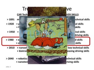
Trends inautomotive
> 1920 + pneumatic systems low high technical skills
+ hydraulic systems low driving skills
> 1950 + electric systems increasing good technical skills
increasing driving skills
> 1980 + electronic systems congestion low technical skills
+ optronic systems starts high driving skills
> 2010 + nanoelectronics congested very low technical skills
+ biotronic systems optimization decreasing driving skills
starts
> 2040 + robotics maximal and no technical skills
+ nanotechnology optimized no driving skills
CAR Technology TRAFFIC DRIVER SKILLS
> 1891 mechanical system very low very high technical skills
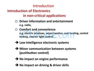
Introduction
Introduction of Electronics
innon-critical applications
Driver information and entertainment
e.g. radio,
Comfort and convenience
e.g. electric windows, wiper/washer, seat heating, central
locking, interior light control …
Low intelligence electronic systems
Minor communication between systems
(pushbutton control)
No impact on engine performance
No impact on driving & driver skills
5.
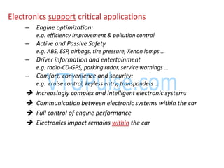
Electronics support criticalapplications
– Engine optimization:
e.g. efficiency improvement & pollution control
– Active and Passive Safety
e.g. ABS, ESP, air ags, tire pressure, Xe o la ps …
– Driver information and entertainment
e.g. radio-CD-GPS, parki g radar, ser i e ar i gs …
– Comfort, convenience and security:
e.g. ruise o trol, keyless e try, tra spo ders …
Increasingly complex and intelligent electronic systems
Communication between electronic systems within the car
Full control of engine performance
Electronics impact remains within the car
6.
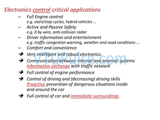
Electronics control criticalapplications
– Full Engine control
e.g. start/stop y les, hy rid ehi les …
– Active and Passive Safety
e.g. X by wire, anti-collision radar
– Driver information and entertainment
e.g. traffi o gestio ar i g, eather a d road o ditio s …
– Comfort and convenience
Very intelligent and robust electronics
Communication between internal and external systems
Information exchange with traffic network
Full control of engine performance
Control of driving and (decreasing) driving skills
Proactive prevention of dangerous situations inside
and around the car
Full control of car and immediate surroundings
9.
slide: 9
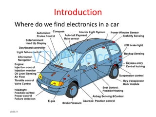
Introduction
Interior LightSystem
Auto toll Payment
Rain sensor
Dashboard controller
Automated
Cruise Control
Light failure control
Information
Navigation
Entertainment
Head Up Display
Engine:
Injection control
Injection monitor
Oil Level Sensing
Air Flow
Headlight:
Position control
Power control
Failure detection
Brake Pressure
Airbag Sensing &Control
Seat control:
Position/Heating
Key transponder
Door module
Keyless entry
Central locking
Throttle control
Valve Control
E-gas
Suspension control
LED brake light
Compass
Stability Sensing
Power Window Sensor
Backup Sensing
Gearbox: Position control
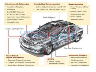
Where do we find electronics in a car
12.
EVOLUTION OF AUTOMOTIVEELECTRONICS
• Electronics have been relatively slow in coming to
the automobile primarily because of the
relationship between the added cost and the
benefits.
• Historically, the first electronics (other than radio)
were introduced into the commercial automobile
during the late 1950s and early 1960s.
• However, these features were not well received by
customers, so they were discontinued from
• production automobiles.
Use of electronicsin automobile
• To improve fuel economy
• To reduce exhaust emissions
16.
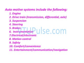
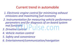
Current trend inautomobile
1. Electronic engine control for minimizing exhaust
emissions and maximizing fuel economy
2. Instrumentation for measuring vehicle performance
parameters and for diagnosis of on-board system
mal functions
3 .Driveline control
4. Vehicle motion control
5. Safety and convenience
6. Entertainment/communication/navigation
17.
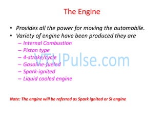
The Engine
• Providesall the power for moving the automobile.
• Variety of engine have been produced they are
– Internal Combustion
– Piston type
– 4-stroke/cycle
– Gasoline-fueled
– Spark-ignited
– Liquid cooled engine
Note: The engine will be referred as Spark ignited or SI engine
18.
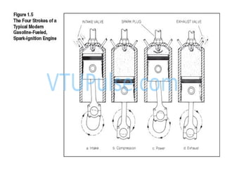
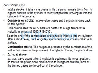
• Conventional SIengines operate using four
strokes, ith either a up or do o e e t of
each piston. These strokes are named
– Intake
– compression,
– Power
– Exhaust
19.
The E gie o ti ued……
• The major components of the engine include following
– Engine Block
– Cylinder
– Crankshaft
– Pistons
– Connecting Rods
– Camshaft
– Cylinder Head
– Valves
– Fuel Control Systems
– Ignition System
– Exhaust System
– Cooling system
– Electrical System
Electronics play a direct role in all aspects of
controlling the engine operations
22.
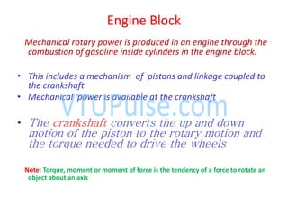
Engine Block
Mechanical rotarypower is produced in an engine through the
combustion of gasoline inside cylinders in the engine block.
• This includes a mechanism of pistons and linkage coupled to
the crankshaft
• Mechanical power is available at the crankshaft
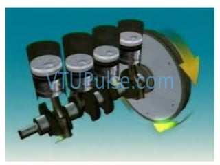
• The crankshaft converts the up and down
motion of the piston to the rotary motion and
the torque needed to drive the wheels
Note: Torque, moment or moment of force is the tendency of a force to rotate an
object about an axis
23.
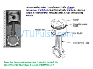
the connecting rodor conrod connects the piston to
the crank or crankshaft. Together with the crank, they form a
simple mechanism that converts linear motion into rotating
motion
Force due to combustion pressure is applied through the
connecting rod to produce a torque at CRANKSHAFT
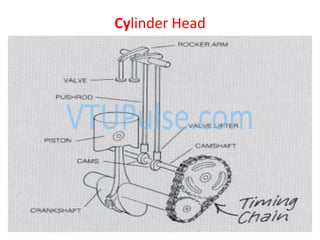
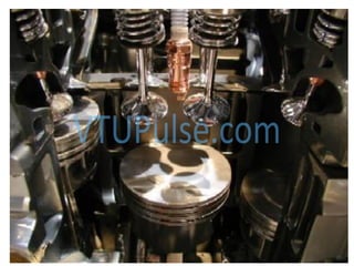
• Contains anIntake and Exhaust valve for each cylinder
• When both valve are closed the head seals the top of the cylinder
• Piston rings seal the bottom of the cylinder
• Valves are operated at off-center cams on the camshaft which is driven by
the crankshaft
• Camshaft rotates at exactly half the speed of crankshaft speed
• The lobe on the cam forces the pushrod upward against one end of the
rocker arm.
• The other end of the rocker arm moves downward and forces the valve
open
27.
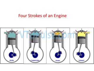
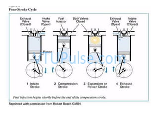
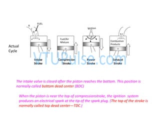
The 4-Stroke Cycle
•The operation of the engine can be understood by considering the actions in
any one cylinder during a complete cycle of the engine
• One complete cycle in the 4-stroke/cycle SI engine requires two complete
rotations of the crankshaft .
• As the crankshaft rotates, the piston moves up and down in the cylinder
• There are four separate strokes of the piston from the top of the cylinder to
the bottom or from the bottom to the top
• Two valves for each cylinder.
– intake valve
– Exhaust valve
Note: The intake valve is normally larger than the exhaust valve
28.
• INTAKE -Downward motion draws in air/fuel
mixture
• COMPRESSION - For higher efficiency
• POWER - Combustion initiated by spark plug
• EXHAUST - Push out burned hydrocarbons
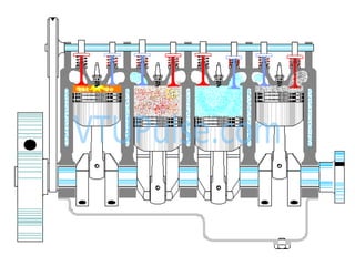
Four-Stroke Engine
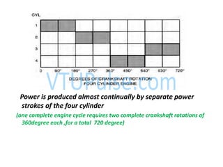
Power is producedalmost continually by separate power
strokes of the four cylinder
(one complete engine cycle requires two complete crankshaft rotations of
360degree each ,for a total 720 degree)
37.
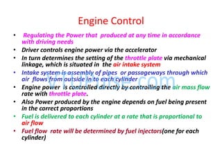
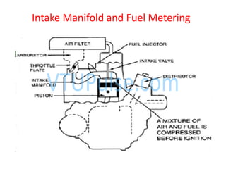
• Regulating thePower that produced at any time in accordance
with driving needs
• Driver controls engine power via the accelerator
• In turn determines the setting of the throttle plate via mechanical
linkage, which is situated in the air intake system
• Intake system is assembly of pipes or passageways through which
air flows from outside in to each cylinder
• Engine power is controlled directly by controlling the air mass flow
rate with throttle plate.
• Also Power produced by the engine depends on fuel being present
in the correct proportions
• Fuel is delivered to each cylinder at a rate that is proportional to
air flow
• Fuel flow rate will be determined by fuel injectors(one for each
cylinder)
Engine Control
Ignition System
• Anignition system is a system for igniting a fuel-air mixture at the right
instant.
• It is best known in the field of internal combustion engines but also has other
applications, e.g. in oil-fired and gas-fired boilers
• Once a stable combustion has been initiated there is no further need for spark
during engine cycle.
• an electric spark produced across the gap between a pair of electrodes of a
spark plug.
• The electric arc or spark provides sufficient energy to cause combustion. This
phenomenon is called ignition.
• Once a stable combustion has been initiated, there is no further need for the
spark during any engine cycle.
• This relatively short period makes spark ignition possible using highly
efficient pulse transformer
40.
Consists of
• Sparkplug
• One or more pulse transformers(coils)
• Timing circuitry
• Distribution apparatus that supplies high voltage pulse
to the correct cylinder
41.
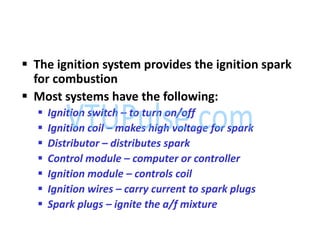
The ignitionsystem provides the ignition spark
for combustion
Most systems have the following:
Ignition switch – to turn on/off
Ignition coil – makes high voltage for spark
Distributor – distributes spark
Control module – computer or controller
Ignition module – controls coil
Ignition wires – carry current to spark plugs
Spark plugs – ignite the a/f mixture
42.
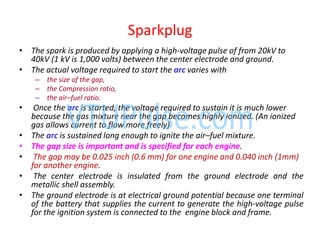
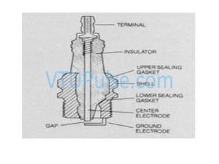
Sparkplug
• The sparkis produced by applying a high-voltage pulse of from 20kV to
40kV (1 kV is 1,000 volts) between the center electrode and ground.
• The actual voltage required to start the arc varies with
– the size of the gap,
– the Compression ratio,
– the air–fuel ratio.
• Once the arc is started, the voltage required to sustain it is much lower
because the gas mixture near the gap becomes highly ionized. (An ionized
gas allows current to flow more freely)
• The arc is sustained long enough to ignite the air–fuel mixture.
• The gap size is important and is specified for each engine.
• The gap may be 0.025 inch (0.6 mm) for one engine and 0.040 inch (1mm)
for another engine.
• The center electrode is insulated from the ground electrode and the
metallic shell assembly.
• The ground electrode is at electrical ground potential because one terminal
of the battery that supplies the current to generate the high-voltage pulse
for the ignition system is connected to the engine block and frame.
44.
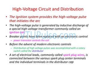
• The ignitionsystem provides the high-voltage pulse
that initiates the arc
• The high-voltage pulse is generated by inductive discharge of
a special high-voltage transformer commonly called an
ignition coil.
• Breaker points have been replaced with an electronic control
– power transistor controls the coil
• Before the advent of modern electronic controls
– Distribution of high voltage pulses was accomplished with a rotary
switch called the distributor
• A set of electrical leads, commonly called spark plug wires, is
connected between the various spark plug center terminals
and the individual terminals in the distributor cap
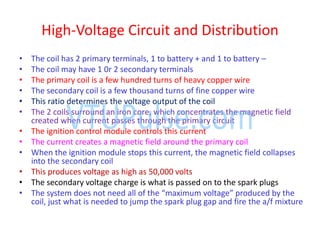
High-Voltage Circuit and Distribution
45.
High-Voltage Circuit andDistribution
• The coil has 2 primary terminals, 1 to battery + and 1 to battery –
• The coil may have 1 0r 2 secondary terminals
• The primary coil is a few hundred turns of heavy copper wire
• The secondary coil is a few thousand turns of fine copper wire
• This ratio determines the voltage output of the coil
• The 2 coils surround an iron core, which concentrates the magnetic field
created when current passes through the primary circuit
• The ignition control module controls this current
• The current creates a magnetic field around the primary coil
• When the ignition module stops this current, the magnetic field collapses
into the secondary coil
• This produces voltage as high as 50,000 volts
• The secondary voltage charge is what is passed on to the spark plugs
• The s ste does ot eed all of the a i u voltage produ ed the
coil, just what is needed to jump the spark plug gap and fire the a/f mixture
46.
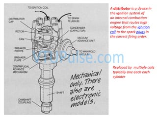
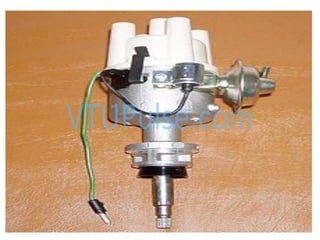
A distributor isa device in
the ignition system of
an internal combustion
engine that routes high
voltage from the ignition
coil to the spark plugs in
the correct firing order.
Replaced by multiple coils
typically one each each
cylinder
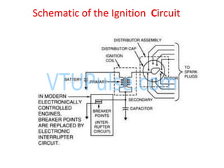
• A contactbreaker (or "points") is a type of electrical switch, and the term
typically refers to the switching device found in the distributor of
the ignition systems of spark-ignition internal combustion engines
• The purpose of the contact breaker is to interrupt the current flowing in the
primary circuit of the ignition coil.
• When this occurs, the collapsing current induces a high voltage in the
secondary winding of the coil, which has many more windings. This causes
a very high voltage to appear at the coil output for a short period - enough
to arc across the electrodes of a spark plug
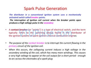
Spark Pulse Generation
The distributor in a conventional ignition system uses a mechanically
activated switch called breaker points.
The interruption of ignition coil current when the breaker points open
produces a high voltage pulse in the secondary
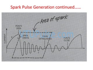
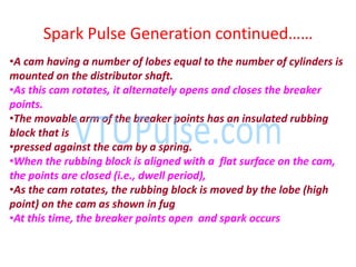
Spark Pulse Geeratio o ti ued……
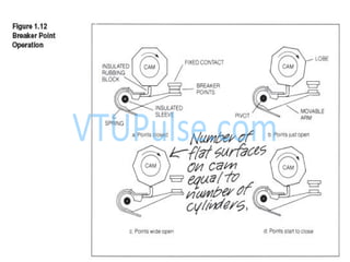
•A cam having a number of lobes equal to the number of cylinders is
mounted on the distributor shaft.
•As this cam rotates, it alternately opens and closes the breaker
points.
•The movable arm of the breaker points has an insulated rubbing
block that is
•pressed against the cam by a spring.
•When the rubbing block is aligned with a flat surface on the cam,
the points are closed (i.e., dwell period),
•As the cam rotates, the rubbing block is moved by the lobe (high
point) on the cam as shown in fug
•At this time, the breaker points open and spark occurs
53.
Ignition Timing
Ignition timingis very important, since the charge is to be ignited just before (few
degrees before BTDC) the end of compression, since when the charge is ignited, it will
take some time to come to the required rate of burning
54.
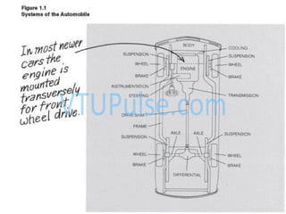
Drive train
The enginedrive train system of the automobile consists of the engine,
transmission, drive shaft, differential, and driven wheels.
Transmission
The transmission provides a match between engine speed and vehicle speed.
The transmission is a gear system that adjusts the ratio of engine speed to
wheel speed
with a manual transmission, the driver selects the correct gear ratio from a set of
possible gear ratios
An automatic transmission selects this gear ratio by means of an automatic
control system
55.
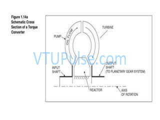
– consists ofa fluid coupling mechanism( torque converter),
– system of planetary gear sets.
• The torque converter is formed from a pair of structures of a
semitoroidal shape
• One of the toroids is driven by the engine by the input shaft.
• The other is in close proximity and is called the turbine.
• Both the pump and the turbine have vanes that are essentially in
axial planes
• In addition, a series of vanes are fixed to the frame and are called
the reactor.
57.
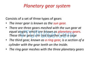
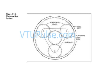
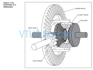
Planetary gear system
Consistsof a set of three types of gears
• The inner gear is known as the sun gear.
• There are three gears meshed with the sun gear at
equal angles, which are known as planetary gears.
These three gears are tied together with a cage
• The third gear, known as a ring gear, is a section of a
cylinder with the gear teeth on the inside.
• The ring gear meshes with the three planetary gears
59.
Pla etary gearsyste o ti ued…
• One or more of these gear systems are held
fixed to the transmission housing via a set of
hydraulically actuated clutches.
60.
Drive Shaft
• Thedrive shaft is used on front-engine, rear
wheel drive vehicles to couple the transmission
output shaft to the differential input shaft.
• Flexible couplings, called universal joints, allow
the rear axle housing and wheels to move up and
down while the transmission remains stationary.
• In front wheel drive automobiles, a pair of drive
shafts couples the transmission to the drive
wheels through flexible joints known as constant
velocity (CV) joints.
61.
The combination ofdrive shaft and differential
completes the transfer of power from the engine
to the rear wheels.
Differential
63.
Differential
The differential servesthree purposes.
1. Right angle transfer of the rotary motion of the
drive shaft to the wheels.
2. To allow each driven wheel to turn at a different
speed.
3. torque increase provided by the gear ratio.
This gear ratio can be changed in a repair shop to
allow different torque to be delivered to the
wheels while using the same engine and
transmission
Brakes
Brakes are basicto the automobile
Responsible for slowing and stopping the vehicle.
•Most of the kinetic energy of the car is dissipated by the brakes during
deceleration and stopping (with the other contributions coming from
aerodynamic drag and tire rolling resistance).
There are two major types of automotive brakes:
• Drum
• Disk brakes.
•Drum brakes are an extension of the types of brakes used on early cars
and horse drawn wagons.
• Increasingly, automobile manufacturers are using disk brakes.
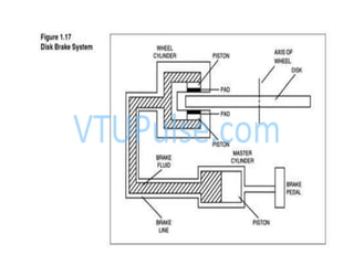
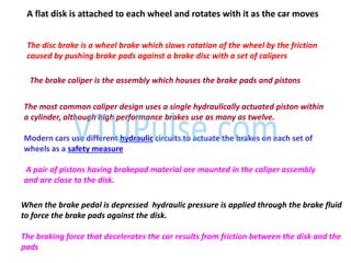
70.
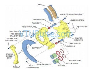
The disc brakeis a wheel brake which slows rotation of the wheel by the friction
caused by pushing brake pads against a brake disc with a set of calipers
The brake caliper is the assembly which houses the brake pads and pistons
The most common caliper design uses a single hydraulically actuated piston within
a cylinder, although high performance brakes use as many as twelve.
Modern cars use different hydraulic circuits to actuate the brakes on each set of
wheels as a safety measure
When the brake pedal is depressed hydraulic pressure is applied through the brake fluid
to force the brake pads against the disk.
The braking force that decelerates the car results from friction between the disk and the
pads
A flat disk is attached to each wheel and rotates with it as the car moves
A pair of pistons having brakepad material are mounted in the caliper assembly
and are close to the disk.
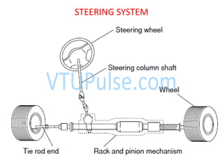
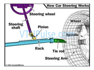
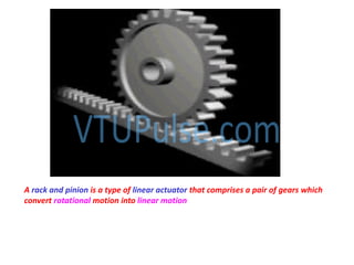
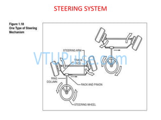
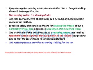
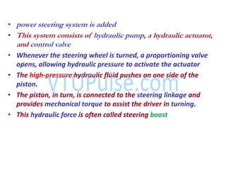
• By operatingthe steering wheel, the wheel direction is changed making
the vehicle change direction
• The steering system is a steering device
• The rack gear connected at both ends by a tie rod is also known as the
rack and pin method.
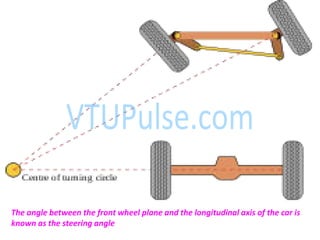
• consisted solely of mechanical means for rotating the wheels about a
nominally vertical axis in response to rotation of the steering wheel
• The inclination of this axis gives rise to a restoring torque that tends to
return the heels to planes that are parallel to the ehicle’s longitudinal
axis so that the car will tend to travel straight ahead
• This restoring torque provides a steering stability for the car
restoring torque torque which tends to bring the moving element back to the mechanical zero of the instrument
78.
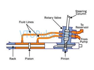
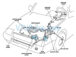
• power steeringsystem is added
• This system consists of hydraulic pump, a hydraulic actuator,
and control valve
• Whenever the steering wheel is turned, a proportioning valve
opens, allowing hydraulic pressure to activate the actuator
• The high-pressure hydraulic fluid pushes on one side of the
piston.
• The piston, in turn, is connected to the steering linkage and
provides mechanical torque to assist the driver in turning.
• This hydraulic force is often called steering boost
80.
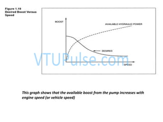
This graph showsthat the available boost from the pump increases with
engine speed (or vehicle speed)