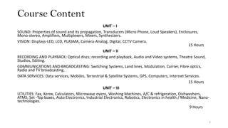
2. Course Learning Objectives
This course will enable the students to
1. Learn and design operating principles of "real world" electronic
devices.
2. Study broader view of key principles of electronic deviceâs operation
and presents a block circuit diagram.
3. Learn to integrate the many different aspects of emerging
technologies and able to build unique mix of skills required for
careers.
2
3. Course Content
UNIT â I
SOUND: Properties of sound and its propagation, Transducers (Micro Phone, Loud Speakers), Enclosures,
Mono-stereo, Amplifiers, Multiplexers, Mixers, Synthesizers.
VISION: Displays-LED, LCD, PLASMA, Camera-Analog, Digital, CCTV Camera.
15 Hours
UNIT â II
RECORDING AND PLAYBACK: Optical discs; recording and playback, Audio and Video systems, Theatre Sound,
Studios, Editing.
COMMUNICATIONS AND BROADCASTING: Switching Systems, Land lines, Modulation, Carrier, Fibre optics,
Radio and TV broadcasting.
DATA SERVICES: Data services, Mobiles, Terrestrial & Satellite Systems, GPS, Computers, Internet Services.
15 Hours
UNIT â III
UTILITIES: Fax, Xerox, Calculators, Microwave ovens, Washing Machines, A/C & refrigeration, Dishwashers,
ATMS, Set -Top boxes, Auto Electronics, Industrial Electronics, Robotics, Electronics in health / Medicine, Nano-
technologies.
9 Hours
3
4. Text Books
TEXTBOOKS:
1. Anand, âConsumer Electronicsâ, Khanna publications, 2011.
2. Bali S. P., âConsumer Electronicsâ, Pearson Education, 2005.
REFERENCE BOOK:
1. Gulati R. R., âModern Television Engineeringâ, Wiley Eastern
4
5. CIE and SEE
Task 1: 3 marks
Task 2: 3 marks
Task 3: 4 marks
Scheme of SEE Question Paper
There will be 8 questions of 20 marks each in the question paper
divided into 3 Units as per the syllabi & contact hours and the student
will have to answer 5 full questions, selecting 2 full questions from Unit
- I & Unit â II and 1 full question from Unit â III.
5
6. Course Content
UNIT â I
SOUND: Properties of sound and its propagation, Transducers (Micro Phone, Loud Speakers), Enclosures,
Mono-stereo, Amplifiers, Multiplexers, Mixers, Synthesizers.
VISION: Displays-LED, LCD, PLASMA, Camera-Analog, Digital, CCTV Camera.
15 Hours
UNIT â II
RECORDING AND PLAYBACK: Optical discs; recording and playback, Audio and Video systems, Theatre Sound,
Studios, Editing.
COMMUNICATIONS AND BROADCASTING: Switching Systems, Land lines, Modulation, Carrier, Fibre optics,
Radio and TV broadcasting.
DATA SERVICES: Data services, Mobiles, Terrestrial & Satellite Systems, GPS, Computers, Internet Services.
15 Hours
UNIT â III
UTILITIES: Fax, Xerox, Calculators, Microwave ovens, Washing Machines, A/C & refrigeration, Dishwashers,
ATMS, Set -Top boxes, Auto Electronics, Industrial Electronics, Robotics, Electronics in health / Medicine, Nano-
technologies.
9 Hours
6
7. Audio Recording
Audio tape (cassette) recorders (ATR/ ACR) perform three basic
functions:
Recording: record particular information and can store the same
Playing: reproduce the recorded information
Erasing: erase out previous recording
7
9. Disc Recording
⢠A needle known as âStylusâ moves on a disc and makes a
âtrackâ on the disc
⢠The stylus is connected with a small motor
9
10. Disc Recording
⢠An armature kept between two poles of permanent magnet
⢠Stylus is attached to the armature
⢠Current of the signal to be recorded âflow through the
armature
⢠Armature experience torque
⢠Stylus moves in accordance with torque
⢠Turn table â rotates disc
⢠Signal track is formed
10
11. Disc
⢠The disc is made of wax or lacquer
⢠It has grooves, which are uniformly spaced in its normal
condition
⢠Modern discs are made of vinyle resins (and not of wax) and
are more flexible
11
15. Course Grooves
15
⢠Approximately 50 grooves per cm of disc can be cut
⢠The speed of disc is 80 RPM
⢠These discs are monophonic type
16. Micro Grooves
16
⢠Much smaller than the coarse grooves
⢠Approximately 100â120 grooves per cm can be cut
⢠They are different for monophonic and stereophonic recordings
⢠The speed of the disc is 35 RPM to 45 RPM
17. Micro Grooves - Types
17
⢠Hill and Dale grooves
⢠Lateral grooves
⢠Stereophonic grooves
18. Micro Grooves - Types
18
Hill and Dale grooves
⢠Used in earlier days.
⢠These grooves were moving up and down, only depth of the groove
was changing whereas, the gap between grooves remained constant
⢠The width of all the grooves was about 150 Οm
19. Micro Grooves - Types
19
Lateral grooves
⢠Stylus moves laterally on the disc
⢠The depth remains constant but width between grooves changes
⢠Better results than the earlier
20. Micro Grooves - Types
20
Stereophonic grooves
⢠These grooves are cut while recording two channels simultaneously
⢠In this system, two channels are recorded on two walls of the groove
inclined at 45° to the horizontal
⢠When currents in the two channels are equal, the stylus moves in the
groove
⢠when the currents are unequal, the stylus will move on one of walls
of the groove depending in which channel, the current is more
22. Stylus or Cutter
22
⢠It is a chisel shaped tool which cuts grooves in the disc
⢠The materials used for its construction are diamond, saphire and
fused aluminium oxide but mostly diamond is preferred which gives
best results
⢠The stylus is mounted on a long screw and moves from edge of the
disc towards its center
⢠The cutter moves radially while the disc has rotatory motion
23. Stylus or Cutter
23
⢠When the cutter moves and cuts the disc, it produces âswarfâ which
should be removed immediately
⢠A suction device is also provided in the cutter
24. Stereophonic Disc Recording Head
24
https://www.youtube.com/watch?v=b2h-v26ylIU
https://www.youtube.com/watch?v=GygFKnwZds8
25. Characteristics of Stylus
25
⢠It should be light in weight, so that it may move at a higher speed
⢠The speed of turn table which rotates the disc should be constant
⢠The stylus should follow the path of sound signal, to be recorded
⢠It should perform faithful recording
27. Cartridges
27
⢠Also called as pickups
⢠Work as microphones in reproduction system
⢠Pickup mechanical vibrations from playback stylus â converts to
original audio signal
⢠Four types
Moving coil type or dynamic cartridges
Magnetic cartridges
Crystal cartridges
Capacitor cartridges
32. Magnetic (Tape) Recording
32
⢠Widely used system for recording audio signals
⢠Basic principle â phenomenon of electromagnetic induction
⢠Audio and video tapes are coated with magnetic material
⢠Audio and video currents induce magnetism in the tape
35. Magnetic Tape Recording â Audio Signals
35
⢠Audio signal given to microphone â converts into electrical pulses
⢠Amplified electrical signal is given to audio head coil â magnetizes the
head
⢠Magnetic strength changes with intensity of audio signal
⢠Magnetized audio head is moved on the audio tape
⢠Audio tape covered with layer of ferromagnetic material â tape is also
magnetized
⢠Magnetic track is formed on tape by magnetic induction
43. Reproduction of Magnetic Recording
43
⢠Play head is moved on tape
⢠Activates play head
⢠Recording magnetic path induces current in play head coil
⢠Induced current is amplified and given to speaker
45. Erasing Magnetic Recording
45
Permanent magnet erasing
⢠Tape is passed through a strong forward and reverse magnetic fields
⢠Forward magnetic field â pulls previous recorded magnetic field
⢠Reverse magnetic field â neutral state
⢠Does not give satisfactory result
⢠Creates noise and distortion during reproduction
46. Erasing Magnetic Recording
46
High frequency erasing
⢠Eraser head has wider air gaps â works at high frequency
⢠Tape is passed over wider air gap â recorded magnetic field is
reversed at a rapid speed
⢠Reversing magnetic field â neutral state
47. Erasing Magnetic Recording
47
Magnetic bulk erasing
⢠Eraser is moved on each side of the tape
⢠Magnetic field on tape turned into neutral state
⢠Less distortion and less noise
48. Comparison â Disc and Magnetic Recording
48
Disc Recording Magnetic Recording
It has moving parts like stylus and therefore
system has more wear and tear
It has no such moving parts and therefore it has
less wear and tear
Disc has short life as it looses its quality with
time
A tape can be played thousand times
Editing and debugging is very difficult Editing and debugging is easy
Immediate playback is not possible Immediate play back is possible
Same disc cannot be used again and again for
recording
Same tape can be used again and again for
recording by erasing the previous content
No modulation noise in disc Presence of modulation noise
50. Optical Recording
50
⢠Process of recording signals on a medium through the use of light
⢠Photographic film has been widely used as the medium
⢠Also called as motion picture recording or photographic recording
⢠Basically a combination of a light source, an optical system, a
photoelectric cell, and a mechanism for moving a film carrying an
optical record by means of which the recorded photographic
variations are converted into electrical signals of approximately
similar form
51. Optical/Motion Picture Recording
51
⢠Optical recording â done on a photo film reel â not on disc or tape
⢠Reproduced with the help of light beam and photo cell (film
projector)
⢠Sound signal is recorded in the form of a photographic image (called
optical sound)
53. Photographic Film or Motion Picture Recording
53
Two methods of sound recording
Variable density method
Variable area method
54. Variable Density Method
54
⢠Weak sound signal is obtained from microphone â first amplified â
then fed to a special vacuum tube
⢠Audio output of the amplifier is fed to anode of vacuum tube called
lamp
⢠Intensity of light coming out from the lamp varies in accordance with
the audio signal
⢠This varying light passes through a slit and a focusing lens
⢠The focused light falls on a moving photographic film where image is
recorded in the form of bars of varying density and distance on the
film
57. Variable Area Method
57
⢠Sound fed to microphone â electrical signal is obtained
⢠Amplified electrical signal is fed to coil of mirror galvanometer
⢠Coil moves â sets mirror into motion
⢠Focused light is made to fall on the mirror â light deflects
⢠Area of the slit opened varies as per sound pressure
58. Variable Area Method
58
⢠Light of constant intensity falls on a slit
⢠Area of slit opened for this light varies in accordance with variation of
sound pressure
⢠Sound is first converted into electrical signals by a microphone
⢠The audio signals are amplified and reach the coil of a mirror
galvanometer
⢠The current carrying coil is placed in a magnetic field and hence,
deflects in accordance with amplitude of the audio signal
⢠A mirror is attached to the coil assembly. The mirror is also deflected
59. Variable Area Method
59
⢠Light from the lamp, duly focused by a lens system, is made to fall on
the mirror
⢠The light reflected from the mirror goes to narrow slit when the
mirror deflects, the slit area exposed to the light changes
⢠The light from the variable area of slit falls on the sound track edge of
the film and is recorded in the form of photograph of variable area
62. Reproduction of Optical Signal
⢠Focused beam of light is made to fall on sound track
⢠Film is moved at designed speed
⢠Light is fed to photo cell â converts into electrical signal
⢠Signal is amplified and passed through loud speaker
62
63. Optical Disc
⢠Electronic data storage medium â written to and read using low
powered laser beam
⢠Laser read the dots â data converted to electrical signal â finally audio
or visual output
63
64. Optical Disc
64
Storage media that holds content in digital format and is read
using a laser assembly is considered optical media
The most common types of optical media are
Blu-ray (BD)
Compact Disc (CD)
Digital Versatile Disc (DVD)
65. Digital Recording
65
⢠Digital recording is becoming popular - done on compact discs (CD)
and digital audio tapes (DAT)
⢠Digital recording is done in Binary code (0, 1)
Advantages of digital recording
(i) A high quality of recording is obtained by digital method
(ii) It is free from noise as signal-noise ratio is quite high
(iii) The recording can be copied for indefinite number of times
68. CD Recording Method
68
⢠Laser beam acts as stylus â modulated by digital audio signal
⢠Audio signal to be recorded is sampled and quantized
⢠Modulated laser is incident on the CD
⢠Laser beam ON â output is 1, OFF â output is 0
⢠Forms pits on the photo resistance material
70. CD Playback
70
⢠Laser beam is incident on CD tracks through mirror
⢠Half polished mirror is used - allows laser to pass but does not allow
it to return
⢠Reflection of laser beam from pits â 0 and space â 1
⢠Reflected beam passed through focusing system and through photo
diode
⢠Output of photo diode fed to digital to analog converter
⢠Analog signal fed to loudspeaker
71. CD Player
71
⢠The audio signal on a CD is recorded in digital form (0, 1)
⢠A pit represents 0 and the flat represents 1
⢠The CD player is a constant linear velocity (CLV) device
⢠The CD contains more information on its outer area as compared to
its inner area, as the diameter goes on decreasing from outer to inner
side
72. CD Player
72
⢠For reproduction, LASER beam is thrown on the tracks
⢠It is reflected from the âflatsâ and not from the âpitsâ
⢠Now the audio digital signal is produced with the help of a photo
diode
⢠Through a digital to analog converter, this signal is converted into
analog and fed to a loudspeaker
73. High Fidelity (HiFi) System
73
⢠Attempts to reproduce full range of audible sound from 20Hz to
20KHz
⢠Uses electronic and electromechanical devices â without distortion
⢠Reproduced sound â exact replica of recorded sound
⢠Fidelity - faithfulness
74. High Fidelity (HiFi) System
74
⢠Completely free from noise â infinite S/N ratio
⢠Should have frequency response from 20Hz to 20KHz â no frequency
distortion
⢠No amplitude or no phase distortion
⢠Should be able to detect the direction of sound
⢠Should create stereophonic (3-dimentional) effects
75. Distortion of Sound in HiFi Systems
75
⢠If the reproduced sound is not an exact replica of the input sound -
output is said to be distorted
(i) Amplitude or non-linear distortion
(ii) Frequency distortion
(iii) Phase distortion
(iv) Transient distortion or hang over
(v) Spatial distortion
76. Amplitude or Non-linear Distortion
⢠This distortion is produced by operating the amplifiers over non-linear
part of its characteristics
⢠The sound becomes rough and hoarse
⢠This distortion takes place in power amplifiers handling very large
powers
76
77. Frequency Distortion
⢠This distortion occurs in the system, when different frequencies of the
signal are not amplified equally
77
78. Phase Distortion
⢠When different frequencies are reproduced in improper time w.r.t. to
each other, phase distortion is said to be occurred
⢠Our ears cannot detect phase shift therefore phase distortion is not
important in audio systems however, it is very important in video
systems
78
79. Transient Distortion or Hang Over
⢠When a system fails to follow sudden large changes in sound level, it
is known as transient distortion
⢠The transients so produced set the loud speaker into vibrations at its
natural frequency
79
80. Spatial Distortion
⢠When a person gets the feeling of wrong location of a sound
⢠In other words, absence of stereophonic effect is known as spatial
distortion
80
81. Components of HiFi System
⢠Radio tuner
⢠Record player/ pick up
⢠Preamplifiers
⢠Poweramplifier
⢠Loud speakers
⢠Tape-recorders
⢠TV.
81
82. Radio Tuner
⢠A ratio tuner is a radio receiver minus amplifier. It performs all the
functionsâtuning, demodulation etc., except the amplification.
82
83. Record Player/Pick-ups
⢠The gramophone pick up , consisting of cartridge and stylus mounted
at one end of the tone arm constitutes starting point of a Hi-Fi system
⢠It should be able to faithfully translate the record âgroovesâ into
corresponding original sound
83
85. Pre-amplifiers
85
⢠The voltage output of a pick up is in millivolts, hence amplification is
necessary
⢠The additional amplification is achieved by using a pre-amplifier
between pick up and the power amplifier
86. Main Amplifier/Power Amplifier
86
⢠The basic function of main amplifier is to strengthen the output of
pre-amplifier to sufficient level so as to drive the loudspeaker
87. Loud Speaker
87
⢠Loud speaker is the most important component of a hi-fi system
⢠It is the last link of a system, and converts electrical signal into the
original sound signal
88. Loud Speaker
88
Co-axial and Tri-axial Speakers
⢠A single speaker cannot cover the whole A.F. range.
⢠To do this, either separate speakers for separate frequency range may
be employed and then interconnected or to mount separate speakers
in a single unit co-axially
90. Film Projector â Important Parts
90
⢠Sprocket: toothed wheels and transport system for reel
⢠Spools: two spools â supply spool and take-up spool. Reel is
unwound from one spool and is wound on the other
⢠Optical System: produces beam of focused light that falls on
sound track of the film
⢠Carbon Arc Lamp: produces a bright parallel beam of light to
be reflected towards optical system
⢠Photo Cell/Photo Diode: Photo cell converts the input signal
into electrical signal
91. Film Projector
91
⢠Reproduction of sound image
⢠Principle of persistence of vision
⢠Projector projects at the rate of 25 pictures/sec to create an
illusion of continuity
⢠A beam of light from optical system passes through film and
gets modulated
⢠Modulated light beam is then incident on photo diode â
produces electrical output
⢠Electrical signal is amplified, processed and fed to loud
speaker