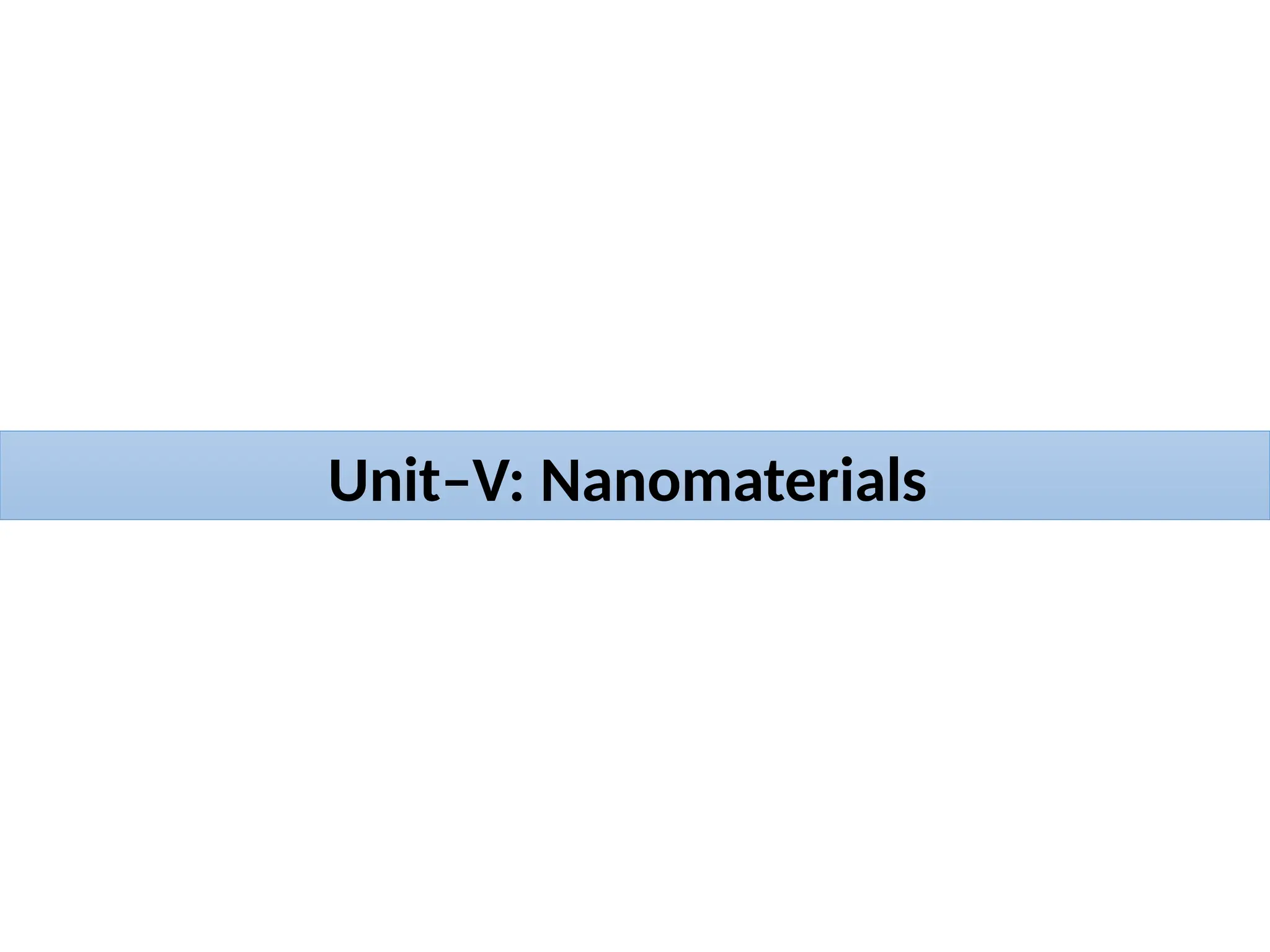
Nano-Scale (1 nm= 10-9
meter)
1 cm = 10 mm = 10 x 1000 mm = 104
x 1000 nm = 107
nm = 107
x 10 Å = 108
Å
1 mm = 1000 mm & 1 mm = 1000 nm & 1 nm = 10 Å = 10 x 10-10
meters = 10-9
meters
3.
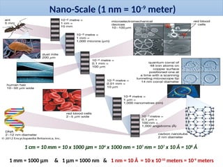
Unit–V: Nanomaterials
Theword “nano” representing very small objects of the range of 1 – 100 nm.
The term “nano” comes from the Greek word “nanos” which means “dwarf
(shortness in height)”
The “nanomaterials” primarily include a class of the materials which are of quite
small size.
3.4 nm
2.5 nm
10 nm
Dwarfism, also known as
short stature, occurs when
an organism is extremely
small. In humans, it is
sometimes defined as an
adult height of less than
147 centimetres (4 ft 10 in)
DNA
Nanocircuit
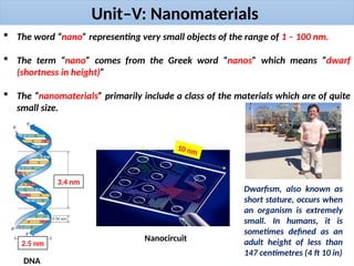
4.
Introduction
What is nanomaterial?
Nanomaterials are
defined as a class of
materials, having at least
one spatial dimension
between 1 to 100 nm.
1 nm = 10-9
meters
1 nm
Dendrimer
Graphene
Carbon
Nanotubes
Fullerene
Liposome
100 nm
2 D
Nanosheet
1 D
Nanotubes
3 D
Nanoparticles
5.
Introduction
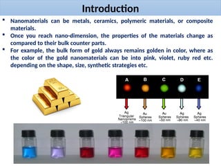
Nanomaterials canbe metals, ceramics, polymeric materials, or composite
materials.
Once you reach nano-dimension, the properties of the materials change as
compared to their bulk counter parts.
For example, the bulk form of gold always remains golden in color, where as
the color of the gold nanomaterials can be into pink, violet, ruby red etc.
depending on the shape, size, synthetic strategies etc.
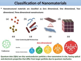
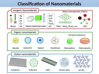
Classification of Nanomaterials
Nanostructured materials are classified as Zero dimensional, One dimensional, Two
dimensional, Three dimensional nanostructures
0 D 1 D 2 D 3 D
Quantum dots (QDs) are tiny semiconductor particles a few nanometres in size, having optical
and electronic properties that differ from larger particles due to quantum mechanics
Zero dimensional
Classification of Nanomaterials
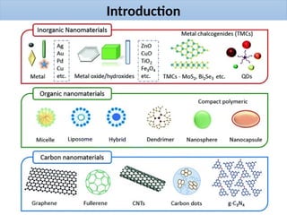
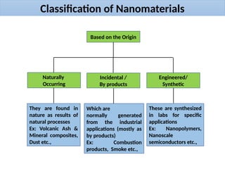
Basedon the Origin
Naturally
Occurring
Incidental /
By products
Engineered/
Synthetic
They are found in
nature as results of
natural processes
Ex: Volcanic Ash &
Mineral composites,
Dust etc.,
Which are
normally generated
from the industrial
applications (mostly as
by products)
Ex: Combustion
products, Smoke etc.,
These are synthesized
in labs for specific
applications
Ex: Nanopolymers,
Nanoscale
semiconductors etc.,
11.
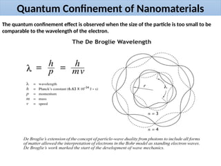
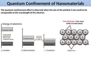
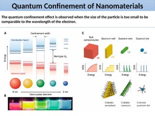
Quantum Confinement ofNanomaterials
The quantum confinement effect is observed when the size of the particle is too small to be
comparable to the wavelength of the electron.
12.
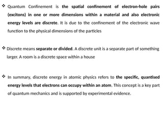
Quantum Confinementis the spatial confinement of electron-hole pairs
(excitons) in one or more dimensions within a material and also electronic
energy levels are discrete. It is due to the confinement of the electronic wave
function to the physical dimensions of the particles
In summary, discrete energy in atomic physics refers to the specific, quantised
energy levels that electrons can occupy within an atom. This concept is a key part
of quantum mechanics and is supported by experimental evidence.
Discrete means separate or divided. A discrete unit is a separate part of something
larger. A room is a discrete space within a house
13.
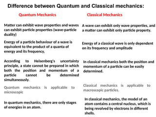
Difference between Quantumand Classical mechanics:
Quantum Mechanics Classical Mechanics
Matter can exhibit wave properties and waves
can exhibit particle properties (wave-particle
duality)
A wave can exhibit only wave properties, and
a matter can exhibit only particle property.
Energy of a particle behaviour of a wave is
equivalent to the product of a quanta of
energy and its frequency,
Energy of a classical wave is only dependent
on its frequency and amplitude
According to Heisenberg's uncertainty
principle, a state cannot be prepared in which
both the position and momentum of a
particle cannot be determined
simultaneously.
In classical mechanics both the position and
momentum of a particle can be easily
determined.
Quantum mechanics is applicable to
microscopic
Classical mechanics is applicable to
macroscopic particles.
In quantum mechanics, there are only stages
of energies in an atom.
In classical mechanics, the model of an
atom contains a central nucleus, which is
being revolved by electrons in different
shells.
14.
Quantum Confinement ofNanomaterials
The quantum confinement effect is observed when the size of the particle is too small to be
comparable to the wavelength of the electron.
15.
Quantum Confinement ofNanomaterials
The quantum confinement effect is observed when the size of the particle is too small to be
comparable to the wavelength of the electron.
16.
Surface to volumeratio of Nanomaterials
The surface to volume ratio of a nanoparticle is defined as the ratio between the surface
area and the volume of the nanoparticle.
An increased surface to volume ratio essentially means an increase in surface area of a
system per unit volume
In case of nanomaterials, this results in an increase in surface atoms as compared to their
bulk counterparts because of difference in the surface energies of bulk and the
nanomaterials. This effect has often found responsible for the improved reactivity, stability
etc. of nanomaterials.
17.
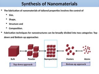
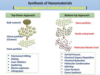
Synthesis of Nanomaterials
The fabrication of nanomaterials of tailored properties involves the control of
Size,
Shape,
Structure and
Composition.
Fabrication techniques for nanostructures can be broadly divided into two categories: Top‐
down and Bottom up approaches
‐
18.
Synthesis of Nanomaterials
(Top-DownApproach & Bottom-UP Approach)
Top-Down Approach Bottom-Up Approach
Bulk material
Macro particles
(Clusters)
Nano particles
Molecular/Atomic level
Nuclei and growth
Nano particles
Mechanical Milling
Etching
Laser Ablation
Sputtering
Electro-explosion
Lithography
Sol-Gel Process
Chemical Vapour Deposition
Chemical Reduction
Molecular Condensation
Spinning
Laser Pyrolysis
Green Synthesis
19.
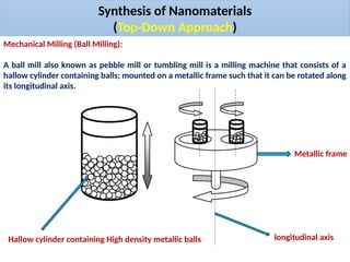
Synthesis of Nanomaterials
(Top-DownApproach)
Mechanical Milling (Ball Milling):
A ball mill also known as pebble mill or tumbling mill is a milling machine that consists of a
hallow cylinder containing balls; mounted on a metallic frame such that it can be rotated along
its longitudinal axis.
Hallow cylinder containing High density metallic balls longitudinal axis
Metallic frame
20.
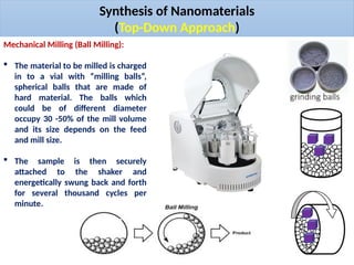
Synthesis of Nanomaterials
(Top-DownApproach)
Mechanical Milling (Ball Milling):
The material to be milled is charged
in to a vial with “milling balls”,
spherical balls that are made of
hard material. The balls which
could be of different diameter
occupy 30 -50% of the mill volume
and its size depends on the feed
and mill size.
The sample is then securely
attached to the shaker and
energetically swung back and forth
for several thousand cycles per
minute.
21.
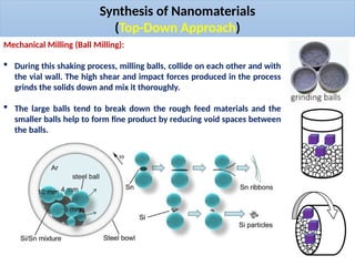
Synthesis of Nanomaterials
(Top-DownApproach)
Mechanical Milling (Ball Milling):
During this shaking process, milling balls, collide on each other and with
the vial wall. The high shear and impact forces produced in the process
grinds the solids down and mix it thoroughly.
The large balls tend to break down the rough feed materials and the
smaller balls help to form fine product by reducing void spaces between
the balls.
22.
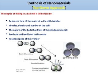
Synthesis of Nanomaterials
(Top-DownApproach)
The degree of milling in a ball mill is influenced by:
Residence time of the material in the mill chamber
The size, density and number of the balls
The nature of the balls (hardness of the grinding material)
Feed rate and feed level in the vessel
Rotation speed of the cylinder
23.
Advantages
It producesvery fine powder (particle size less than or equal to 10 microns).
It is suitable for milling toxic materials since it can be used in a completely enclosed form.
Has a wide application.
It can be used for continuous operation.
It is used in milling highly abrasive materials.
Disadvantages
Contamination of product may occur as a result of wear and tear which occurs principally
from the balls and partially from the casing.
High machine noise level especially if the hollow cylinder is made of metal, but much less if
rubber is used.
Relatively long milling time.
It is difficult to clean the machine after use.
Synthesis of Nanomaterials
(Top-Down Approach)
24.
Synthesis of Nanomaterials
(Bottom-UpApproach)
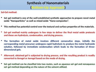
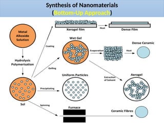
Sol-Gel method:
Sol–gel method is one of the well-established synthetic approaches to prepare novel metal
oxide “Nanoparticles” as well as mixed oxide “Nano-composites”.
This method has potential control over the textural and surface properties of the materials.
Sol–gel method mainly undergoes in few steps to deliver the final metal oxide protocols
and those are hydrolysis, condensation, and drying process.
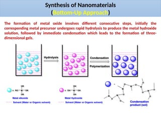
The formation of metal oxide involves different consecutive steps, initially the
corresponding metal precursor undergoes rapid hydrolysis to produce the metal hydroxide
solution, followed by immediate condensation which leads to the formation of three-
dimensional gels.
Afterward, obtained gel is subjected to drying process, and the resulting product is readily
converted to Xerogel or Aerogel based on the mode of drying.
Sol–gel method can be classified into two routes, such as aqueous sol–gel and nonaqueous
sol–gel method depending on the nature of the solvent utilized.
25.
Synthesis of Nanomaterials
(Bottom-UpApproach)
M OR
OR
RO
OR
=
Metal alkoxide
Solvent (Water or Organic solvent)
Hydrolysis
M OH
OH
OH
OH
=
Metal Hydroxide
Solvent (Water or Organic solvent)
O
O
O
O
O
O
M
O
M
M
M
M
M
O
O
Condensation
product (sol)
Condensation
Polymerization
=
The formation of metal oxide involves different consecutive steps, initially the
corresponding metal precursor undergoes rapid hydrolysis to produce the metal hydroxide
solution, followed by immediate condensation which leads to the formation of three-
dimensional gels.
Synthesis of Nanomaterials
(Bottom-UpApproach)
Advantages
As the process is based on chemical reactions in liquid phase, it is very simple technique.
It is also cost-effective, as very simple accessories are required for the chemical reaction
and deposition procedures.
As the deposition is done in liquid phase, the process is versatile enough to produce a large
form of materials starting from aerogel, xerogel, ceramic materials, micro-/nano-powders,
nanostructured thin films, nano- · particles/nano-wires/nano-rods/nano-pillars, etc.
Due to the chemistry involved in the process, a large range of materials can be deposited
by this procedure.
Due to the liquid phase deposition, large and complex shaped substrates can also be coated
by this process.
Possibility of high purity of starting material can also be achieved.
Precise control over the doping level is also easier in this process.
28.
Synthesis of Nanomaterials
(Bottom-UpApproach)
Disadvantages
The process is not very ‘clean’. As the process involves chemical reactions between several
ingredients in solution, it contains undesired atoms, molecules, ions, etc., in the required
material, which deteriorates the electrical as well as optical properties of the deposited
material. Therefore, this technique is not compatible with the modern solid-state device
fabrication technique, which is the primary manufacturing process for electronic and
photonic devices.
29.
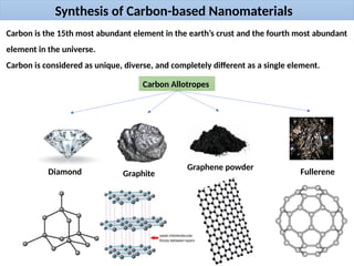
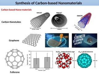
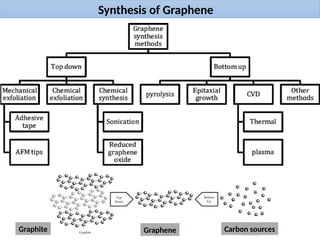
Synthesis of Carbon-basedNanomaterials
Carbon is the 15th most abundant element in the earth’s crust and the fourth most abundant
element in the universe.
Carbon is considered as unique, diverse, and completely different as a single element.
Carbon Allotropes
Diamond Graphite
Graphene powder
Fullerene
30.
Synthesis of Carbon-basedNanomaterials
Carbon based Nano-materials
Carbon-Nanotubes
Graphene
Fullerene
31.
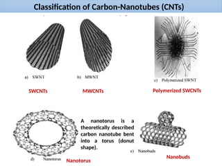
Classification of Carbon-Nanotubes(CNTs)
SWCNTs MWCNTs Polymerized SWCNTs
Nanotorus
Nanobuds
A nanotorus is a
theoretically described
carbon nanotube bent
into a torus (donut
shape).
32.
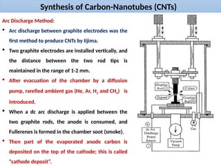
Synthesis of Carbon-Nanotubes(CNTs)
Arc Discharge Method:
Arc discharge between graphite electrodes was the
first method to produce CNTs by Iijima.
Two graphite electrodes are installed vertically, and
the distance between the two rod tips is
maintained in the range of 1-2 mm.
After evacuation of the chamber by a diffusion
pump, rarefied ambient gas (He, Ar, H2 and CH4) is
introduced.
When a dc arc discharge is applied between the
two graphite rods, the anode is consumed, and
Fullerenes is formed in the chamber soot (smoke).
Then part of the evaporated anode carbon is
deposited on the top of the cathode; this is called
“cathode deposit”.
33.
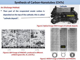
Synthesis of Carbon-Nanotubes(CNTs)
Arc Discharge Method:
Then part of the evaporated anode carbon is
deposited on the top of the cathode; this is called
“cathode deposit”.
Figure1: Optical Image (TEM image) of Cathode deposit.
Cathode
MWCNTs
Figure2: HRTEM image of DWCNTs and MWCNTs
3 nm
Figure3: SEM image of MWCNTs produced in different
ambient gases (He, Ar, and CH4)
Synthesis of Carbon-Nanotubes(CNTs)
Arc Discharge Method:
Then part of the evaporated anode carbon is deposited on the top of the cathode; this is
called “cathode deposit”.
The addition of a catalyst like Fe, Y, S, Ni and Mo leads to the formation of the single-walled
carbon nanotubes (SWCNTs).
Factors influencing the size and structure of CNTs by Arc Discharge Method:
A number of variables such as
Temperature of the chamber,
The composition and concentration of the catalyst
The presence of ambient gases, etc., influence their size and structure
Advantages of Arc Discharge Method:
MWCNTs doped with boron and nitrogen can be produced by using the arc discharge
method.
SWCNT–SWCNT hybrids can be produced by arc discharge in open air at less cost.
36.
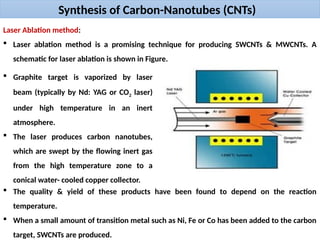
Synthesis of Carbon-Nanotubes(CNTs)
Laser Ablation method:
Laser ablation method is a promising technique for producing SWCNTs & MWCNTs. A
schematic for laser ablation is shown in Figure.
Graphite target is vaporized by laser
beam (typically by Nd: YAG or CO2 laser)
under high temperature in an inert
atmosphere.
The laser produces carbon nanotubes,
which are swept by the flowing inert gas
from the high temperature zone to a
conical water- cooled copper collector.
The quality & yield of these products have been found to depend on the reaction
temperature.
When a small amount of transition metal such as Ni, Fe or Co has been added to the carbon
target, SWCNTs are produced.
37.
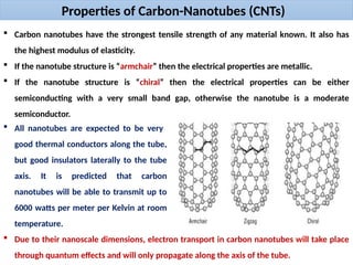
Properties of Carbon-Nanotubes(CNTs)
Carbon nanotubes have the strongest tensile strength of any material known. It also has
the highest modulus of elasticity.
If the nanotube structure is “armchair” then the electrical properties are metallic.
If the nanotube structure is “chiral” then the electrical properties can be either
semiconducting with a very small band gap, otherwise the nanotube is a moderate
semiconductor.
All nanotubes are expected to be very
good thermal conductors along the tube,
but good insulators laterally to the tube
axis. It is predicted that carbon
nanotubes will be able to transmit up to
6000 watts per meter per Kelvin at room
temperature.
Due to their nanoscale dimensions, electron transport in carbon nanotubes will take place
through quantum effects and will only propagate along the axis of the tube.
38.
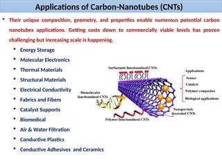
Applications of Carbon-Nanotubes(CNTs)
Their unique composition, geometry, and properties enable numerous potential carbon
nanotubes applications. Getting costs down to commercially viable levels has proven
challenging but increasing scale is happening.
Energy Storage
Molecular Electronics
Thermal Materials
Structural Materials
Electrical Conductivity
Fabrics and Fibers
Catalyst Supports
Biomedical
Air & Water Filtration
Conductive Plastics
Conductive Adhesives and Ceramics
39.
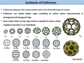
Synthesis of Fullerenes
Fullerenes belong to the carbon family and it is the third allotrope of carbon.
Fullerenes are closed hollow cages consisting of carbon atoms interconnected in
pentagonal and hexagonal rings.
Each carbon atom on the cage surface is bonded to three carbon
neighbors therefore is sp2
hybridized.
C60
Buckyball
40.
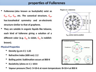
properties of Fullerenes
Fullerenes (also known as buckyballs) exist as
C60, C70, C80, etc. The canonical structure, C60,
has icosahedral symmetry and an electronic
structure similar to that of graphene.
They are soluble in organic liquids like toluene,
each kind of fullerene giving a solution of a
different color (e.g. C60 is violet, C70 is reddish-
brown).
Physical Properties
Density (g.cm-3 ): 1.65
Refractive index (600 nm): 2.2
Boiling point: Sublimation occurs at 800 K
Resistivity (ohms m-1 ): 1014
Vapour pressure (Torr): 5×10⁻⁶ at room temperature: 8×10⁻⁴ at 800 K
41.
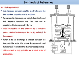
Synthesis of Fullerenes
ArcDischarge Method:
Arc discharge between graphite electrodes was the
first method to produce CNTs by Iijima.
Two graphite electrodes are installed vertically, and
the distance between the two rod tips is
maintained in the range of 1-2 mm.
After evacuation of the chamber by a diffusion
pump, rarefied ambient gas (He, Ar, H2 and CH4) is
introduced.
When a dc arc discharge is applied between the
two graphite rods, the anode is consumed, and
Fullerenes is formed in the chamber soot (smoke).
This method is only suitable for a small scale of
production.
42.
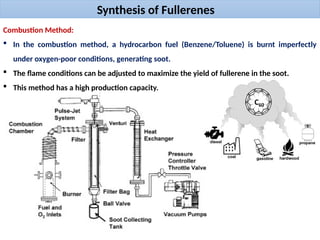
Synthesis of Fullerenes
CombustionMethod:
In the combustion method, a hydrocarbon fuel (Benzene/Toluene) is burnt imperfectly
under oxygen-poor conditions, generating soot.
The flame conditions can be adjusted to maximize the yield of fullerene in the soot.
This method has a high production capacity.
43.
Applications of Fullerenes
Fullerene(either itself or as a combination with other materials) can be utilized in diverse
applications which majorly include:
Artificial photosynthesis
Cosmetics (Personal
Care Products)
Surface coatings
Military armor
Powerful anti-oxidant
Anti-allergic
Chemical sensors
Inhibitor of HIV
Hollow success–cancer treatment
Drug/Antibody/Gene-delivery system
MRI contrast agents
Photodynamic therapy and X-ray contrast reagents
44.
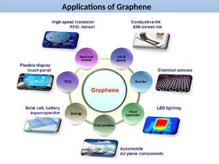
Synthesis of Graphene
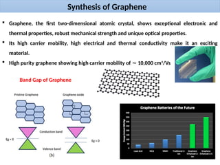
Graphene, the first two-dimensional atomic crystal, shows exceptional electronic and
thermal properties, robust mechanical strength and unique optical properties.
Its high carrier mobility, high electrical and thermal conductivity make it an exciting
material.
High purity graphene showing high carrier mobility of 10,000 cm
∼ 2
/Vs
Band Gap of Graphene
Synthesis of Graphene
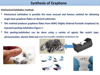
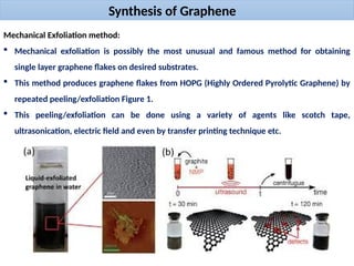
MechanicalExfoliation method:
Mechanical exfoliation is possibly the most unusual and famous method for obtaining
single layer graphene flakes on desired substrates.
This method produces graphene flakes from HOPG (Highly Ordered Pyrolytic Graphene) by
repeated peeling/exfoliation Figure 1.
This peeling/exfoliation can be done using a variety of agents like scotch tape,
ultrasonication, electric field and even by transfer printing technique etc.
47.
Synthesis of Graphene
MechanicalExfoliation method:
Mechanical exfoliation is possibly the most unusual and famous method for obtaining
single layer graphene flakes on desired substrates.
This method produces graphene flakes from HOPG (Highly Ordered Pyrolytic Graphene) by
repeated peeling/exfoliation Figure 1.
This peeling/exfoliation can be done using a variety of agents like scotch tape,
ultrasonication, electric field and even by transfer printing technique etc.
48.
Synthesis of Graphene
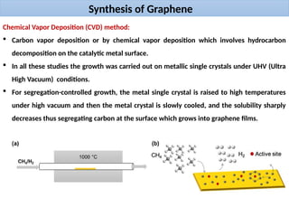
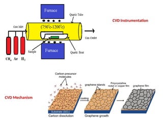
ChemicalVapor Deposition (CVD) method:
Carbon vapor deposition or by chemical vapor deposition which involves hydrocarbon
decomposition on the catalytic metal surface.
In all these studies the growth was carried out on metallic single crystals under UHV (Ultra
High Vacuum) conditions.
For segregation-controlled growth, the metal single crystal is raised to high temperatures
under high vacuum and then the metal crystal is slowly cooled, and the solubility sharply
decreases thus segregating carbon at the surface which grows into graphene films.