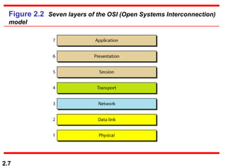
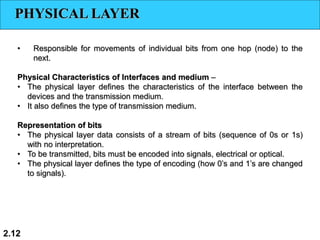
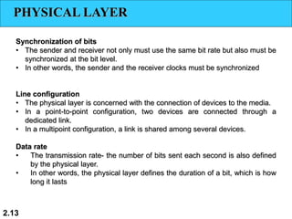
3. 2.3
2-1 LAYERED TASKS
We use the concept of layers in our daily life. As
an example, let us consider two friends who
communicate through postal mail. The process of
sending a letter to a friend would be complex if
there were no services available from the post
office.
Sender, Receiver, and Carrier
Hierarchy
Topics discussed in this section:
5. 2.5
2-2 THE OSI MODEL
Established in 1947, the International Standards
Organization (ISO) is a multinational body
dedicated to worldwide agreement on
international standards. An ISO standard that
covers all aspects of network communications is
the Open Systems Interconnection (OSI) model. It
was first introduced in the late 1970s.
Layered Architecture
Peer-to-Peer Processes
Encapsulation
Topics discussed in this section:
10. 2.10
2-3 LAYERS IN THE OSI MODEL
In this section we briefly describe the functions
of each layer in the OSI model.
Physical Layer
Data Link Layer
Network Layer
Transport Layer
Session Layer
Presentation Layer
Application Layer
Topics discussed in this section:
12. 2.12
PHYSICAL LAYER
• Responsible for movements of individual bits from one hop (node) to the
next.
Physical Characteristics of Interfaces and medium –
• The physical layer defines the characteristics of the interface between the
devices and the transmission medium.
• It also defines the type of transmission medium.
Representation of bits
• The physical layer data consists of a stream of bits (sequence of 0s or 1s)
with no interpretation.
• To be transmitted, bits must be encoded into signals, electrical or optical.
• The physical layer defines the type of encoding (how 0’s and 1’s are changed
to signals).
13. 2.13
PHYSICAL LAYER
Synchronization of bits
• The sender and receiver not only must use the same bit rate but also must be
synchronized at the bit level.
• In other words, the sender and the receiver clocks must be synchronized
Line configuration
• The physical layer is concerned with the connection of devices to the media.
• In a point-to-point configuration, two devices are connected through a
dedicated link.
• In a multipoint configuration, a link is shared among several devices.
Data rate
• The transmission rate- the number of bits sent each second is also defined
by the physical layer.
• In other words, the physical layer defines the duration of a bit, which is how
long it lasts
14. 2.14
PHYSICAL LAYER
Physical topology
• defines how devices are connected to make a network.
• Devices can be connected by using a
• mesh topology (every device is connected to every other device),
• star topology (devices are connected through a central device),
• ring topology (each device is connected to the next, forming a ring),
• bus topology (every device is on a common link), or
• hybrid topology (this is a combination of two or more topologies).
Transmission mode
• defines the direction of transmission between two devices: simplex, half-
duplex, or full-duplex.
• In simplex mode, only one device can send; the other can only receive. The
simplex mode is a one-way communication.
• In half-duplex mode, two devices can send and receive, but not at the same
time.
• In full-duplex (or simply duplex) mode, two devices can send and receive at
the same time.
15. 2.15
The physical layer is responsible for movements of
individual bits from one hop (node) to the next.
Note
17. 2.17
DATA LINK LAYER
• Responsible for moving frames from one hop (node) to the next
• Framing- The data link layer divides the stream of bits received from the network
layer into manageable data units called frames
• Physical addressing - If frames are to be distributed to different systems on the
network, the data link layer adds a header to the frame to define the sender and/or
receiver of the frame.
• If the frame is intended for a system outside the sender’s network, the receiver
address is the address of the device that connects the network to the next one.
18. 2.18
DATA LINK LAYER
• Flow control - If the rate at which the data are absorbed by the receiver is less than
the rate at which data are produced in the sender, the data link layer imposes a flow
control mechanism to avoid overwhelming the receiver.
• Error control - The data link layer adds reliability to the physical layer by adding
mechanisms to detect and retransmit damaged or lost frames. It also uses a mechanism
to recognize duplicate frames. Error control is normally achieved through a
trailer added to the end of the frame.
• Access control - When two or more devices are connected to the same link, data
link layer protocols are necessary to determine which device has control over the
link at any given time.
22. 2.22
NETWORK LAYER
Responsible for delivery of individual packets from source host to the destination
host
Logical addressing
• The physical addressing implemented by the data link layer handles the
addressing problem locally.
• If a packet passes the network boundary, we need another addressing
system to help distinguish the source and destination systems.
• The network layer adds a header to the packet coming from the upper layer
that, among other things, includes the logical addresses of the sender and
receiver
Routing
• When independent networks or links are connected to create internetworks
(network of networks) or a large network, the connecting devices (called
routers
24. 2.24
The network layer is responsible for the
delivery of individual packets from
the source host to the destination host.
Note
25. 2.25
Questions
1) The physical layers involve ________.
a) Optical, electrical and mechanical properties
b) Voltage levels, timing and frequency
c) Physical connections
d) All of the above
2) Who developed standards for OSI reference model?
a) ANSI - American National Standards Institute
b) ISO - International Standards Organization
c) IEEE - Institute of Electrical and Electronics Engineers
d) ACM - Association for Computing Machinery
3) Which is the layer of OSI model that employs error detection?
a) Session
b) Network
c) Physical
d) Data Link
27. 2.27
TRANSPORT LAYER
Responsible for delivery of message from one process to another
Service-point addressing (Port address)
• Computers often run several programs at the same time. So, source-to-
destination delivery means delivery not only from one computer to the next
but also from a specific process (running program) on one computer to a
specific process (running program) on the other.
• The transport layer header must therefore include a type of address called a
service-point address (or port address).
• The network layer gets each packet to the correct computer; the transport
layer gets the entire message to the correct process on that computer.
Segmentation and reassembly
• A message is divided into transmittable segments, with each segment
containing a sequence number.
• These numbers enable the transport layer to reassemble the message
correctly upon arriving at the destination and to identify and replace packets
that were lost in transmission
28. 2.28
TRANSPORT LAYER
Connection control
• The transport layer can be either connectionless or connection-oriented.
• A connectionless transport layer treats each segment as an independent
packet and delivers it to the transport layer at the destination machine.
• A connection oriented transport layer makes a connection with the transport
layer at the destination machine first before delivering the packets.
• After all the data are transferred, the connection is terminated.
Flow control
• Like the data link layer, the transport layer is responsible for flow control.
• However, flow control at this layer is performed end to end rather than
across a single link.
Error control
• Like data link layer, transport layer is responsible for error control. However,
error control at this layer is performed process-to-process rather than
across a single link.
• The sending transport layer makes sure that the entire message arrives at
the receiving transport layer without error (damage, loss, or duplication).
• Error correction is usually achieved through retransmission.
32. 2.32
SESSION LAYER
Responsible for dialog control and synchronization
Dialog Control
• The session layer allows two systems to enter into a dialog.
• It allows the communication between two processes to take place in either
half duplex or full-duplex mode
Synchronization
• The session layer allows a process to add checkpoints, or synchronization
points, to a stream of data.
• For example, if a system is sending a file of 2000 pages, it is advisable to
insert checkpoints after every 100 pages to ensure that each 100-page unit is
received and acknowledged independently.
• In this case, if a crash happens during the transmission of page 523, the only
pages that need to be resent after system recovery are pages 501 to 523.
Pages previous to 501 need not be resent.
35. 2.35
PRESENTATION LAYER
It is concerned with syntax and semantics of information exchanged between two
systems.
It is responsible for translation, compression, and encryption
Translation
• Processes (running programs) in two systems are usually exchanging information in
the form of character strings, numbers, and so on.
• Information must be changed to bit streams before being transmitted. Because
different computers use different encoding systems, presentation layer is
responsible for interoperability between these different encoding methods.
• Presentation layer at the sender changes the information from its sender-dependent
format into a common format.
• Presentation layer at the receiving machine changes the common format into its
receiver-dependent format.
36. 2.36
PRESENTATION LAYER
Encryption
• To carry sensitive information, a system must be able to ensure privacy.
• Encryption means that the sender transforms the original information to another
form and sends the resulting message out over the network.
• Decryption reverses the original process to transform the message back to its
original form
Compression
• Data compression reduces the number of bits contained in the information.
• Data compression becomes particularly important in the transmission of
multimedia such as text, audio, and video
38. 2.38
APPLICATION LAYER
Responsible for providing services to the user
• Of the many application services available, the figure 2.14 shows only three:
• XAOO (message-handling services),
• X.500 (directory services), and
• File transfer, access, and management (FTAM).
• The user in this example employs XAOO to send an e-mail message
Network virtual terminal
• A network virtual terminal is a software version of a physical terminal
• It allows a user to log on to a remote host.
• To do so, the application creates a software emulation of a terminal at the remote
host. The user's computer talks to the software terminal which, in turn, talks to the
host and vice versa.
• The remote host believes it is communicating with one of its own terminals and
allows the user to log on.
39. 2.39
APPLICATION LAYER
File transfer, access, and management
• This application allows a user
• to access files in a remote host (to make changes or read data),
• to retrieve files from a remote computer for use in the local computer, and
• to manage or control files in a remote computer locally.
Mail services
• This application provides the basis for e-mail forwarding and storage.
Directory services.
• This application provides distributed database sources and access for global
information about various objects and services