Unit 1.1: CAD for Electronics: SPICE Simulation and overview
1.
CAD FOR ELECTRONICS
UNIT 1: Pspice overview, Symbols and Conventions, Basic
Analyses, DC Sweep and other DC Calculations, AC Sweep[3]
UNIT 2: Analyzing waveforms with Pspice, Pspice Stimulus Editor,
and Pspice Model Editor[2]
UNIT 3: Files needed for Simulations, Netlist File, Circuit File, Model
Library, Stimulus File, Include File, Wave Form Data File, Pspice
Output File [3]
UNIT 4: Simulation Examples, Example Circuit Creations,
Preparing Design for Simulations, Creating Parts for Modeling,
Creating and Editing Models [4]
2.
UNIT-01
Pspice overview
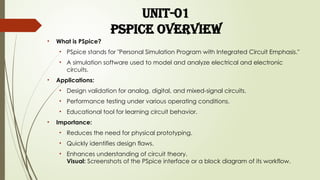
• Whatis PSpice?
• PSpice stands for "Personal Simulation Program with Integrated Circuit Emphasis."
• A simulation software used to model and analyze electrical and electronic
circuits.
• Applications:
• Design validation for analog, digital, and mixed-signal circuits.
• Performance testing under various operating conditions.
• Educational tool for learning circuit behavior.
• Importance:
• Reduces the need for physical prototyping.
• Quickly identifies design flaws.
• Enhances understanding of circuit theory.
Visual: Screenshots of the PSpice interface or a block diagram of its workflow.
3.
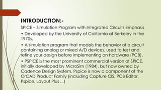
INTRODUCTION:-
SPICE – SimulationProgram with Integrated Circuits Emphasis
• Developed by the University of California at Berkeley in the
1970s.
• A simulation program that models the behavior of a circuit
containing analog or mixed A/D devices, used to test and
refine your design before implementing on hardware (PCB).
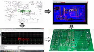
• PSPICE is the most prominent commercial version of SPICE,
initially developed by MicroSim (1984), but now owned by
Cadence Design System. Pspice is now a component of the
OrCAD Product Family (including Capture CIS, PCB Editor,
Pspice, Layout Plus ...)
5.
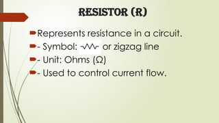
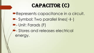
Introduction to Symbolsin PSpice
Symbols in PSpice represent electrical
components and are essential for circuit
simulation. They help in designing and
understanding electronic circuits. Commonly
used symbols include resistors, capacitors,
inductors, voltage sources, and ground.
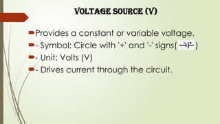
Voltage Source (V)
Providesa constant or variable voltage.
- Symbol: Circle with '+' and '-' signs( )
- Unit: Volts (V)
- Drives current through the circuit.
10.
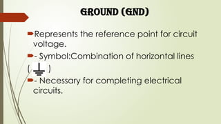
Ground (GND)
Represents thereference point for circuit
voltage.
- Symbol:Combination of horizontal lines
( )
- Necessary for completing electrical
circuits.
11.
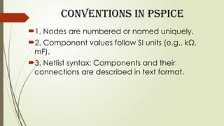
Conventions in PSpice
1.Nodes are numbered or named uniquely.
2. Component values follow SI units (e.g., kΩ,
mF).
3. Netlist syntax: Components and their
connections are described in text format.
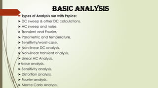
BASIC ANALYSIS
Typesof Analysis run with Pspice:
➤ DC sweep & other DC calculations.
➤ AC sweep and noise.
➤ Transient and Fourier.
➤ Parametric and temperature.
➤ Sensitivity/worst-case.
➤ Non-linear DC analysis.
➤ Non-linear transient analysis.
➤ Linear AC Analysis.
➤Noise analysis.
➤ Sensitivity analysis.
➤ Distortion analysis.
➤ Fourier analysis.
➤ Monte Carlo Analysis.
![CAD FOR ELECTRONICS
UNIT 1: Pspice overview, Symbols and Conventions, Basic
Analyses, DC Sweep and other DC Calculations, AC Sweep[3]
UNIT 2: Analyzing waveforms with Pspice, Pspice Stimulus Editor,
and Pspice Model Editor[2]
UNIT 3: Files needed for Simulations, Netlist File, Circuit File, Model
Library, Stimulus File, Include File, Wave Form Data File, Pspice
Output File [3]
UNIT 4: Simulation Examples, Example Circuit Creations,
Preparing Design for Simulations, Creating Parts for Modeling,
Creating and Editing Models [4]](https://image.slidesharecdn.com/unit-11-260119133411-11509992/85/Unit-1-1-CAD-for-Electronics-SPICE-Simulation-and-overview-1-320.jpg)
![CAD FOR ELECTRONICS
UNIT 1: Pspice overview, Symbols and Conventions, Basic
Analyses, DC Sweep and other DC Calculations, AC Sweep[3]
UNIT 2: Analyzing waveforms with Pspice, Pspice Stimulus Editor,
and Pspice Model Editor[2]
UNIT 3: Files needed for Simulations, Netlist File, Circuit File, Model
Library, Stimulus File, Include File, Wave Form Data File, Pspice
Output File [3]
UNIT 4: Simulation Examples, Example Circuit Creations,
Preparing Design for Simulations, Creating Parts for Modeling,
Creating and Editing Models [4]](https://image.slidesharecdn.com/unit-11-260119133411-11509992/75/Unit-1-1-CAD-for-Electronics-SPICE-Simulation-and-overview-1-2048.jpg)