The document is a service manual for Micro-SPA power spa packs. It provides troubleshooting flow charts and step-by-step procedures for common error conditions displayed on the keypad such as flashing dots, incorrect temperature readings, and a flashing display. It also includes instructions for performing low level programming and replacing components such as the spa pack.
This document provides troubleshooting information for technical problems with SSPA-1 & SSPA-MP SPA PACKS. It contains flow charts and step-by-step procedures to help identify and resolve issues like flashing dots on the display, temperature errors, pumps or other components not working properly. The document aims to give service technicians a complete explanation of specific problems through overview charts and more detailed repair instructions.
This document describes how to use pulse width modulation (PWM) to fade an LED's brightness level in and out with a microcontroller. PWM works by varying the duty cycle of digital pulses sent to the LED, which the eye perceives as varying brightness. To achieve a smooth fade, logarithmic values are used for the duty cycle since LED brightness increases logarithmically. The circuit uses a PIC microcontroller to generate the PWM signal controlling an LED via a transistor. Software increments through logarithmic brightness values to fade the LED in and out over time.
The document discusses the remote control system in televisions. It begins by defining remote control and its functional units. It then describes the various components of the remote control transmitter and receiver. The transmitter uses an infrared LED to transmit digital codes representing buttons pressed on the remote. The receiver uses a photodiode to receive these signals which are then decoded by an integrated circuit. It provides examples of how volume control works, with the remote sending a "volume up" signal which is received and processed to gradually increase the volume. Memory circuits are also discussed for retaining settings between uses.
STMicroelectronics offers smart solutions for wearable devicesST_World
The document discusses analog integrated circuits produced by STMicroelectronics that are designed for wearable devices. It describes ST's portfolio of analog components including operational amplifiers, current sensors, audio amplifiers, smart reset ICs, analog switches, battery gas gauges, BlueNRG Bluetooth chip, and MEMS microphones. These components are optimized for applications in consumer fitness/wellness devices, healthcare/medical devices, portable infotainment, and industrial monitoring. The document provides details on the features and specifications of sample products within each component category.
If you encounter any problems or need assistance, contact HydroQuip's Technical Support staff by calling (909) 273-7575. HydroQuip is located at 13345 Estelle Street, Corona, CA 92879 and can also be reached via their website at www.hydroquip.com or by email at hq@hydroquip.com. The document provides contact information for HydroQuip's Technical Support staff and lists their address, phone number, fax number, website, and email.
This document is a technical service manual from Balboa Instruments that provides guidance on servicing Balboa control systems for spas. It includes sections on safety, required tools and components, system descriptions, troubleshooting wiring and voltage issues, testing circuit boards, changing circuit boards, filter settings, optional features, and information on specific Balboa circuit board models. The manual aims to help qualified technicians safely service Balboa control systems.
This document provides installation instructions for Balboa SUV series power systems for portable spas. It includes important safety instructions, an overview of system configurations, considerations for installation such as ventilation and drainage requirements, instructions for installing power system components like pumps and air blowers, and electrical connection details. The document also includes a warranty information and technical support contact details.
The document repeatedly lists the website http://www.MyPoolSpas.com and a phone number, 920-925-3094. It appears to advertise wholesale pool and spa parts available for purchase at MyPoolSpas.com or by calling the given phone number.
The document provides installation instructions for the air.wav blower system. It includes warnings about proper installation and use. The specifications section lists the blower's dimensions, ratings, and airflow/pressure capabilities. Installation instructions specify fastening the blower brackets, using flexible piping, and making electrical connections according to codes. Connecting an optional keypad is also addressed.
The document contains contact information for a wholesale pool and spa parts business called MyPoolSpas.com, including their website address http://www.MyPoolSpas.com and phone number 920-925-3094, which is repeated multiple times.
The document provides troubleshooting steps for an error condition where three flashing dots appear on the keypad display of an MSPA-MP spa pack. This typically indicates a problem with the pressure switch. The steps include checking for proper pump operation, continuity on the pressure switch, adjusting or replacing the pressure switch, and replacing the pressure switch cable or circuit board if needed. Diagrams are provided to illustrate pressure switch wiring and location of components.
The document summarizes the replacement of an in.k155 remote stereo control with a new in.k175 keypad. The in.k175 has improved waterproofing and sealing. It can be used as a direct replacement for the in.k155, though it is shorter so a spacer ring is needed for some installations. The in.k155 will no longer be available for production or service.
The document provides installation and programming instructions for the Hayward 2100 Series pool and spa control system. It allows for monitoring and controlling up to 12 functions for pool system control and environment control from a main remote control unit. The system can control equipment such as pumps, lighting, heaters, and other devices. The document outlines electrical specifications, safety instructions, system components, installation of sensors and control panels, wiring, configuration, programming and troubleshooting.
The document contains contact information for a company called MyPoolSpas.com that sells wholesale pool and spa parts, including their website address http://www.MyPoolSpas.com and phone number 920-925-3094. This information is repeated multiple times.
The in.terface is a waterproof box that connects accessories like audio/video devices, keypads, and switches to Aeware spa systems. It comes in two configurations - one for audio/video control and one for auxiliary keypads. It is installed under the spa skirt in an upright position for watertightness. Connections to devices are made via color-coded terminals. Power is provided by connecting the in.terface to the spa pack; no power shutdown is needed except when using the auxiliary keypad version, which requires a spa pack reset after installation.
This document provides information about a hot tub control system including its model number, circuit board layout, connections for pumps, lights, blowers, and other components. It also describes dip switch and jumper settings that configure options like temperatures units, pump speeds, and other functions. Wiring diagrams are included for connecting an optional ozone generator at either 120V or 240V.
To control an iPod connected to the in.p3 dock using the in.k600 keypad, press the Mode key to select Audio mode, select CDC source, then use the multifunction keys to select tracks, change albums, repeat songs or play randomly while the Next key navigates menu pages.
The document provides an overview of the in.xm spa pack platform from Pentair. It highlights several innovative features of the in.xm including its waterproof enclosure, breakthrough connectors, kinetic heat monitoring system, dry-fire protection, board access prevention design, and intelligent water temperature algorithm. The in.xm is described as the safest and most reliable spa pack platform for manufacturers.
The document provides instructions for a SmarTouch Digital spa control system. It cautions that the control system can be susceptible to static discharge and humidity. Only certified electricians should access components inside the control box due to high voltage levels. The manual explains how to set the spa temperature and time of day, describes the functions of the control panel keys, and lists possible error messages and their meanings.
The document provides instructions for operating and programming a Mini Max digital spa control system. It describes:
- The startup purge process and default temperature setting
- How to activate pumps, lights, heat, and other functions using control panel keys
- The factory programming procedure for settings like temperature range, pump configuration, and purge frequency
- Troubleshooting tips for issues like no display, freezing errors, overheating errors, and no heat output
The document provides troubleshooting information for an MSPA-MP spa pack. It describes that 3 flashing dots on the display indicates a pressure switch problem. The troubleshooting steps include verifying pump operation, checking pressure switch continuity, and adjusting or replacing the pressure switch. If the problem persists, the pressure switch cable or circuit board may need to be replaced.
The document provides instructions for operating a solid-state pool/spa control system, including how to use the power switch, check for proper voltage, and troubleshoot issues using the visual diagnostic system lights. Safety warnings are also given regarding risks like electric shock, hyperthermia, and proper water temperature. The system uses fuses to protect components and lights on the cord connections help diagnose if proper voltage is reaching each part.
This document provides instructions and safety warnings for the SmarTouch Digital spa control system.
[1] SmarTouch controls are susceptible to static discharge and high humidity, so do not allow water to enter the control box.
[2] High voltages inside the control box can cause injury or electrocution, so only certified technicians should access the box.
[3] The control system is operated from the control panel without opening the box. If service is needed, contact the manufacturer.
The document provides information about operating a SmarTouch Digital spa control system, including:
- The control system can be easily operated without programming, or customized through programming. High voltage levels inside the control box present a risk of injury, so only certified technicians should access the interior.
- The main functions include setting the temperature using the TEMP and SET keys, and pressing SET after use to initiate filtration cycles. Additional optional devices like pumps, blowers, and lights are controlled using other keys.
- Status messages on the control panel display water temperature, time of day, and error codes. Error messages indicate issues like low/over temperatures or other system faults that may require correction.
This document provides installation instructions for an air series pool and spa control system. It covers considerations for installation location and plumbing, how to connect system components, electrical installation procedures, special considerations for lights, blowers, startup and pressure switch adjustment. Troubleshooting tips are also mentioned. The document includes diagrams of the control system and component connection colors. Installation must be done by a licensed electrician according to all applicable electrical codes.
This document is an owner's manual for a spa. It provides safety instructions for installing and using the spa, including warnings about electric shock, drowning, and hyperthermia. It also contains information about water quality maintenance, spa specifications, control functions, troubleshooting, and maintenance procedures.
The document provides information about the in.k100 auxiliary keypad for controlling pool and spa equipment. It has keys to control pumps, lighting, and other functions. It is compact and waterproof for outdoor use. Installation involves using a template to cut an opening and mounting the keypad using an adhesive gasket. Connections to control systems are made using an in.link connector.
This document provides instructions for operating an infrared remote control for a pool or spa. It includes:
1. A key chart explaining the functions of each button on the remote control.
2. Instructions for programming the remote to control up to three home entertainment or automation devices by entering their unique four-digit codes.
3. Procedures for replacing batteries, searching for codes if a device is not responding, checking stored codes, and putting the remote into learning mode to add new functions from an original remote control.
The document provides information about the in.k400 keypad for controlling pool and spa equipment. It includes installation instructions for mounting the waterproof keypad using adhesive or brackets. Connection details are given for linking the keypad to an in.xm control unit. The functions of the keys are described for controlling pumps, lights, programs and settings. Specifications cover dimensions, temperature range, weight and standards compliance.
This document provides troubleshooting tips for Brettline pool and spa control systems models BL-40, BL-40TC, and BL-40 COMBO. It identifies common problems such as low pump speed, no pump operation, and no heat. Troubleshooting tips include checking for proper control panel operation, reviewing system wiring diagrams, and testing specific control system components. Replacement parts that may be needed include control panels, temperature sensors, circuit boards, and transformers.
The document provides contact information for HydroQuip's Technical Support staff, including their address, website, email, and phone and fax numbers. It encourages readers to contact Technical Support if they encounter any problems or need assistance. It also notes that "THE SMART CHOICE" is HydroQuip's slogan.
This document provides instructions for troubleshooting problems with the Ultimate Series spa control system. It describes how to identify error messages through flashing dots on the temperature display and illuminated LED indicators. Instructions are provided for adjusting the pressure switch if it is activated when the pump is not running. The document also covers general installation considerations for Hydro-Quip solid-state control packs.
We have Baumer make DP Transmitters. DP Transmitters are also known as Differential Pressure Transmitters, Pressure Difference Transmitters, PD Transmitters, DP Transmitters
This document provides instructions for installing an outdoor pool and spa system. It discusses:
- Having a qualified electrician install the electrical components according to code
- Connecting the system to a dedicated circuit protected by a GFCI
- Connecting components such as pumps, blowers, and lights to color-coded receptacles
- Configuring universal circuits for 120V or 240V operation
- Installing the control panel and temperature sensor
- Connecting a gas heater according to the manufacturer's instructions
- Bypassing pressure or flow switches if needed
- Adjusting the pressure switch if issues arise related to water flow
The document provides instructions for installing and using the in.k450 keypad for controlling in.xm and in.xe spa systems. It describes how to physically install the keypad, make connections, and use the various buttons to control spa functions like pumps, lights, temperature, and programming filter cycles or economy modes. Installation involves drilling holes and attaching the keypad using the provided template and adhesive gasket. Connection to the spa system is also described.
This document provides an owner's manual for a Master Spas hot tub. It includes sections on safety instructions, installation, water chemistry, spa controls, maintenance, and troubleshooting. The safety instructions warn of risks of electric shock, injury, accidental drowning, and hyperthermia. It also provides instructions on electrical installation, chemical treatment of spa water, and winterizing the spa.
This document is an owner's manual for a Master Spas Legacy spa. It includes sections on safety instructions, electrical installation, water chemistry, spa operation instructions, troubleshooting, and maintenance. The manual provides information to help owners install, use, and care for their spa safely and properly.
BTech ECE project final report using ArduinoBhuvi85107
This is my original work. The notes I have made on some pages were learnt over time, you can incorporate them in your electronics hobbying (although this site is mostly used for copying projects and not learning haha). Feel free to use any part of the project.
This document provides specifications for the Canon iR2200/iR2800/iR3300 copier. Key specifications include:
- It is a desktop copier with a fixed copyboard. Light source is a xenon lamp and lens is a lens array. The photosensitive medium is an OPC drum that is 30mm in diameter.
- Systems used include indirect electrostatic reproduction, AC roller charging, laser exposure, auto density adjustment, single-component toner projection development, auto paper pickup from two front cassettes that can hold around 500 and 550 sheets of 80g/m2 and 64g/m2 paper respectively. Manual feeding is also available. Transfer is via roller and separation
This document contains the user manual for a solar power regulator system. It includes sections describing the general information, system summary, hardware components, circuit schematic, potential issues, program flowchart, and full program code. The solar power regulator uses a PIC microcontroller to monitor voltage from solar panels and temperature of a power containment unit (PCU). It can display readings on an LCD, trigger a fan if temperature exceeds limits, and disconnect power if voltage or temperature thresholds are exceeded. The full program code for running the regulator is provided.
This document provides instructions for wiring the North American model of the in.xe spa control system. It describes stripping wires, connecting them to the appropriate terminals according to the label, securing the cable, and connecting the bonding conductor. Proper wiring of the electrical service box, GFCI, and in.xe terminal block is essential according to electrical codes.
The document provides instructions for operating a SmarTouch Digital spa control system. It contains 3 pages of information:
1) An introduction explaining that the control system is easy to use and only requires setting the temperature and pressing SET when finished.
2) Instructions for setting the temperature and using the SET key to start filtration cycles.
3) An explanation of the control panel keys and their functions for controlling devices like pumps, blowers, lights, and setting filtration time.
This document provides instructions for adjusting various settings on a spa control panel, including temperature unit (F or C), time of day, economy mode start time and duration, panel lock, and descriptions of default settings and modes like economy mode and freeze protection. Settings are adjusted using the program, list, enter and up/down arrow keys, and confirmed with enter. Error codes are displayed as flashing dots and require servicing.
The document provides instructions for operating various functions of a spa or hot tub. It describes the economy mode which maintains water temperature 20°F below the set point. It also describes the freeze protection mode which activates the pump and heater if water drops below certain temperatures. Default settings are described such as filtration cycles running for 1 hour every 24 hours with water at 95°F. Instructions are provided for operating pumps, blowers, lights and setting the temperature. Error codes and troubleshooting tips are also summarized.
This document provides installation and operation instructions for a PS-9704 series pool/spa control system. It includes guidelines for installing remote heaters, making electrical and wet connections, programming filtration settings, and troubleshooting. Safety precautions are outlined, and a wiring diagram and parts list are provided.
The document provides installation and operation instructions for a Platinum Series pool and spa control system. It includes details on installing remote heaters, electrical connections, temperature sensors, equipment connections, and programming filtration settings. Safety instructions are provided at the beginning regarding proper installation and use of the system.
The document provides installation instructions for PS-6502 & PS-6503 Platinum Series pool and spa control systems. It describes how to install the heater in different locations including on the bottom, back, or top of the control box using adjustable clamps or slide brackets. The instructions also cover electrical installation, temperature sensor placement, equipment connections, and programming filtration settings. Additional sections provide details on optional equipment, operational considerations, troubleshooting, and warranty information.
The document provides information on the default system operation, freeze protection modes, high temperature error handling, filtration cycles, pump and blower controls, light controls, temperature setting, and error identification for a spa or pool system. When power is applied, the system will initiate a default 24-hour filtration cycle at 95°F. It describes two modes of freeze protection below 59°F and 49°F and will suspend filtration if temperatures exceed 115°F or reach errors.
The document provides instructions for operating and programming a spa, including:
- If the water temperature exceeds 115°F, the heater will turn off, and above 122°F all outputs will disable until cooled.
- The filtration cycle can be programmed to run 1, 2, or 3 times daily for 60, 120, 180, or 480 minutes each cycle.
- By default, the spa will filter for 1 hour every 24 hours, maintaining the temperature at 95°F.
- Instructions are provided for operating the pump, accessory, light, and adjusting the temperature settings.
- The system enters a freeze protection mode if the temperature drops below 59°F by turning the pump on periodically.
The document provides instructions for operating and programming a spa control system. It describes how the system handles high temperatures, allows setting filter cycles for 1-3 times daily and durations of 60-180 minutes, and will default to a 24-hour filter cycle at 95°F if power is lost. It also explains how to operate the pump, light, and change the temperature setting, and describes freeze protection and error identification features.
This document summarizes the revision history of PCB part number 33-0024-Rx from the initial R0 revision in January 1999 through the current R6 revision. It describes the changes made at each revision level such as PCB layout changes, software changes, additions of memory and removal of features. It also provides information to help identify the correct wiring diagram for a given revision level.
This document provides instructions for an Eco 1 timed filtration system. It states to press and hold the light button to change the duration of filtration, and to press and hold the pump button to change the number of times filtration will occur. It also provides contact information for My Pool and Spas, a wholesale pool and spa parts supplier.
The document provides instructions for setting various operating parameters of a pool or spa control system including time, filtration start/duration, temperature display units, panel lock, economy mode, freeze protection, and error conditions. It describes pressing the program key to access each setting and using up/down arrows to adjust before pressing program to save. It also lists default settings if power is lost.
The changes include:
- Two programmable filtration cycles, one for AM and one for PM.
- A new "Smart Summer Mode" that operates pumps and chlorinators during cooler times when temperatures exceed a threshold.
- Optional programming via Palm Pilot or keypad.
- New auxiliary circuit and circulation pump options.
- Updated owner's manuals to reflect changes.
This document provides contact information for a wholesale pool and spa parts business called MyPoolSpas.com. It lists their phone number as 920-925-3094. The business sells wholesale pool and spa parts.
This document provides contact information for a company called MyPoolSpas.com Spa Parts Wholesale Pool. They sell pool and spa parts and can be reached by calling 920-925-3094. The document lists the name of the company and their phone number.
The document provides instructions for programming various settings on an HT-2 / 9600 Series spa control system, including time of day, filtration cycle start time and duration, economy mode start time and duration, temperature units (Fahrenheit or Celsius), and a spa-side lock feature. It also describes low level programming options that can be changed by positioning jumpers on the system board, including pump, blower, light, ozone, fiber optics, clock, current, circulation pump, and sensor calibration settings.
The document discusses four jumpers on a system board that can be positioned to change parameters of an equipment system. Jumper 1 sets either a high or low current limit. Jumper 2 selects whether temperature is displayed in Fahrenheit or Celsius. Jumpers 3 and 4 determine if the pumps run as single or two speed pumps. Positioning the jumpers allows customizing the system's operation based on electrical specifications and pump configuration.
The document provides instructions for programming a Palm Pilot PDA to communicate with and adjust the low-level programming of Hydro-Quip control systems. The PDA must have the Serve-Soft 2 software installed and unlocked using the username "Hydro-Quip" and password "Hq92u1". An ADIR-1 cartridge is used to connect the PDA to the control system. Low-level parameters can then be viewed and modified on the PDA screen by tapping selections. Additional features like current states, troubleshooting, and documentation can also be accessed.
This document provides a template for installing spaside controls for pool and spa equipment. The template is only to be used with ECO-1, 2, 5, and 6 series controls and measures 2 5/8 inches by 2 5/8 inches with two 1 inch holes. Installers are directed to refer to the installation manual for details on installation.
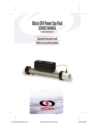
1. Micro-SPA Power Spa Pack
SERVICE MANUAL
• by Gecko Electronics Inc. •
Visual step-by-step guide to easily
identify & correct technical problems!
http://www.MyPoolSpas.com Wholesale Pool and Spa Parts 920-925-3094
2. Table of Contents
Topics covered in this manual are as follows:
Power & Ground Check
Electrical Wiring 6
GFCI 7
Programming
Low Level Programming 10
Error Conditions
3 Flashing Dots Appearing on Keypad Display 11
3 Flashing Dots (with pressure switch) 13
Display Is Flashing 17
Wrong Temperature Appearing on Keypad Display 21
Troubleshooting
Nothing Seems to Work! 23
Spa Does Not Heat! 25
Pump 1 Does Not Work! 27
Light Does Not Work! 29
Ozonator Does Not Work! 31
Keys Do Not Work! 33
How to ...
Replace The Spa Pack 35
Adjust The Pressure Switch 37
Miscellaneous
Professional Repair Kit Info 39
http://www.MyPoolSpas.com Wholesale Pool and Spa Parts 920-925-3094
3. In an attempt to make this manual as useful as possible, it has been presented in two
formats. Problem-solving solutions are described with Troubleshooting Flow Charts
and also with Step-by-Step Procedures.
The two formats together should provide an overall complete explanation, with flow
charts providing an overview of specific problems, and step-by-step procedures giving
more detailed information.
Important Safety Information
WARNING: Risk of electrical shock! All procedures described in this service manual
must only be performed by qualified personnel, in accordance with the
standards applicable in the country of installation and, whenever
possible, with the equipment powered off. When connecting the
equipment, always refer to the wiring diagram affixed to the inside of
your spa pack’s power box cover! This diagram always prevails over
the wiring diagram at the end of this manual.
All information given subject to technical modifications without notice.
http://www.MyPoolSpas.com Wholesale Pool and Spa Parts 920-925-3094
4. Tools & Parts
Tools, test equipment and components needed to carry
out Micro-SPA power spa pack service calls.
Required tools:
Pliers 3/8"
open end wrench
Phillips & flat screwdrivers Jumper cable
11/32" nut driver Multimeter
1/4" open end wrench GFCI tester & digital thermometer (optional)
Required pack parts:
Regulation sensor
Micro-SPA complete pack
Top side control (keypad)
Gecko Electronic Inc. sells Professionnal Repair Kits that include everything needed for Micro-SPA power spa pack servicing.
For more information, go to the last page of this manual.
http://www.MyPoolSpas.com Wholesale Pool and Spa Parts 920-925-3094
5. 4 Micro-SPA Power Spa Pack Service Manual
http://www.MyPoolSpas.com Wholesale Pool and Spa Parts 920-925-3094
6. Keypads
Micro-SPA single- and dual-pump systems are available with
a selection of keypads.
All the procedures and instructions described in the next pages are applicable to
Micro-SPA systems equipped with one of the following keypads. Please note that the
TSC-9 model is used througout this manual to illustrate specific actions.
TSC-9 Keypad (2" • 4 1/2")
Micro-SPA Power Spa Pack Service Manual 5
http://www.MyPoolSpas.com Wholesale Pool and Spa Parts 920-925-3094
7. Electrical Wiring
Correct wiring of the electrical service box, GFCI box and pack terminal
bloc is essential.
1• Carry out a visual inspection to check for signs of miswiring.
Refer to supplied wiring diagrams.
Call an electrician if necessary.
6 Micro-SPA Power Spa Pack Service Manual
http://www.MyPoolSpas.com Wholesale Pool and Spa Parts 920-925-3094
8. GFCI Flow Chart
If GFCI trips, follow this Troubleshooting Flow Chart to identify
the problem:
yes no
Is GFCI
properly connected?
Verify
Wiring Diagram
and reconnect it.
yes no
Unplug everything
including the light cord.
Is GFCI
still tripping? Reconnect
one component
at a time until
GFCI starts tripping.
Replace Replace defective
GFCI cord. component.
Replace Spa Pack
if GFCI
is still tripping.
Micro-SPA Power Spa Pack Service Manual 7
http://www.MyPoolSpas.com Wholesale Pool and Spa Parts 920-925-3094
9. GFCI Trips!
If all connections are made, but nothing seems to be working, you probably
have a power supply problem. If GFCI continues to trip even after having
replaced the transformer, carry out the following tests to correct the problem:
Note that for new installations, GFCI trippings due to miswiring are common.
If breaker is wired properly, GFCI trippings may occur when total amount of current
drawn by spa exceeds breaker rating.
A current leak to ground will also cause GFCI to trip. If any of the components is faulty
and a leak of more than 5mA occurs, GFCI will trip to prevent electrocution.
1• If GFCI is properly connected, but
still tripping, unplug all outputs the
light cord.
2• If GFCI still trips, replace GFCI cord.
Replace Spa Pack if problem persist.
If it stops tripping, reconnect one
component at a time until GFCI
starts tripping. Replace defective
component.
8 Micro-SPA Power Spa Pack Service Manual
http://www.MyPoolSpas.com Wholesale Pool and Spa Parts 920-925-3094
10. Low Level Programming
Some Micro-SPA spa pack parameters can be modified
by changing the Low Level Programming.
Low Level Programming:
To access low level programming, press and hold Light key for 20 seconds, after
which the first parameter code should appear on the display.
Use Up and Down keys to modify parameter values and Light key to change from
one parameter to the next. You must go through all parameters to exit this mode.
If you do not wish to change a parameter, simply press Light key to advance to the
next parameter.
List of parameter configurations
1- Current limiting option
Display: HC or LC
Value of x: HC = High Current
breaker.
LC = Low Current
breaker.
2- Pump speed configuration
Display: SPx
Value of x: 1 = 1 speed
2 = 2 speed
3- Temperature unit
Display: Tux (TuC)
Value of x: F = Fahrenheit
C = Celsius
4- Light
Display: L1 or L2
Value of x: L1 = 1 intensity
L2 = 2 intensity
Micro-SPA Power Spa Pack Service Manual 9
http://www.MyPoolSpas.com Wholesale Pool and Spa Parts 920-925-3094
11. 10 Micro-SPA Power Spa Pack Service Manual
http://www.MyPoolSpas.com Wholesale Pool and Spa Parts 920-925-3094
12. Flashing Dots Flow Chart
If 3 flashing dots appear on keypad display, follow Troubleshooting Flow
Chart below to identify the problem. If spa is equipped with a pressure
switch, refer to page 13.
3 flashing dots appear on the display!
yes no
Reset breaker.
Are dots still
flashing on System
keypad display? works fine.
no yes
Touch heater barrel.
Does it feel hot?
yes no
Does the jets The problem was
feel strong? caused by a blockage
of water in the piping.
Look for valve closed,
anything trapped
Verify water level Verify for air lock, in piping, etc.
and if the dry fire pump problem or if
probe is properly there is not enough
connected. water in the spa.
If error persist
replace Spa Pack.
If error persist If error persist
replace Spa Pack. replace Spa Pack.
Micro-SPA Power Spa Pack Service Manual 11
http://www.MyPoolSpas.com Wholesale Pool and Spa Parts 920-925-3094
13. Flashing Dots Displayed
If 3 flashing dots appear on keypad display, follow the troubleshooting
chart below to identify the problem.
There must be enough water in the spa for normal operations. System may detect error
condition if spa filter is dirty or if something restricts flow of water in piping.
The heater will automatically shut down when error condition occurs.
Power may remain On when the following steps are carried out.
1• Shut power off and power your spa 5• If so, verify water level and if the dry
up again to reset the system. If error fire probe is connected properly.
persist, verify if Pump 1 is working. If
pump is not working right, refer to 6• If condition still persist replace spa
pump section of this manual. pack.
7• If you do not have adequate water
flow coming out the jets check for
air locks, pump problems or
insufficient water level in the spa.
8• If condition still persist replace spa
pack.
2• If Pump 1 is working properly, turn it
on by pressing Pump 1 key (or start
pump 1 by increasing the set point).
Check if heater barrel feels hot. If so,
shut system off and remove any
obstructions in the piping ie: dirty
filter, clogged jets, etc. Clear any air
locks and verify water valves.
3• If condition still persist after power up
replace spa pack.
4• However if the error code is still
present and the heater is at a normal
tempearture: check the flow of water
coming out the jets and make sure
the flow is strong.
12 Micro-SPA Power Spa Pack Service Manual
http://www.MyPoolSpas.com Wholesale Pool and Spa Parts 920-925-3094
14. Flashing Dots Flow Chart
Note: for spa equipped with a pressure switch only.
If 3 flashing dots appear on keypad display, follow Troubleshooting Flow
Chart below to identify the problem.
3 flashing dots appear on the display!
yes no
Reset breaker.
Is error still appear
on the display?
System
yes no works fine.
Touch the
heater barrel.
Does it feel hot?
Remove anything
obstructing filter
canister or piping.
Clear any air locks. yes no
Verify water valves.
Do you have
continuity on your
voltmeter for
pressure switch? Short pressure
switch terminals
with a jumper cable.
yes no
Disconnect yes no
pressure switch
for 5 seconds
and reconnect it. Are dots still
Verify Try to adjust flashing on
pressure pressure switch. keypad display?
switch Are dots still
flashing on Replace Remove anything
connection. Spa Pack. obstructing filter canister
keypad display?
or piping. Clear any air
locks. Verify water valves.
Replace pressure
switch if problem
If problem persists, persists.
replace Spa Pack.
Try to adjust
pressure switch.
Replace pressure
switch if problem
persists.
Micro-SPA Power Spa Pack Service Manual 13
http://www.MyPoolSpas.com Wholesale Pool and Spa Parts 920-925-3094
15. Flashing Dots Displayed
Three flashing dots error condition indicates a pressure switch problem.
There must be enough water in the spa for normal operations. System may detect an error
condition if spa filter is dirty or if something restricts flow of water in the piping.
The heater will automatically shut down when error condition occurs.
Power may remain On when the following steps are carried out.
1• Shut power off and power your spa
up again to reset the system. If error
persist, verify if Pump 1 is working. If
pump is not working right, refer to
pump section of this manual.
5• If you do not detect continuity, verify
if pressure switch is properly
connected to pressure switch.
2• If Pump 1 is working properly, turn it 6• Ensure adequate water flow in the
on by pressing Pump 1 key (or start heater and short the two pressure
pump1 by increasing the set point). switch terminals with a jumper cable.
Check if heater barrel feels hot.
7• If the three dots disappear, first
If so, shut system off and remove any make sure there is no blockage of
obstructions in the piping ie: dirty water or air lock and check water
filter, clogged jets, etc. Clear any air valves.
locks and verify water valves.
If the installation is older than 2 years,
3• If heater is at a normal temperature: replace the pressure switch and re-
with Pump 1 working, test continuity calibrate it.
on the pressure switch.
If installation is recent, try readjusting
4• If you detect continuity, go to step the pressure switch. If this is not
# 10. possible, replace switch.
(Refer to "How to Adjust the
Pressure Switch" section of this
manual.)
14 Micro-SPA Power Spa Pack Service Manual
http://www.MyPoolSpas.com Wholesale Pool and Spa Parts 920-925-3094
16. Flashing Dots Displayed
Power may remain On while the following steps are carried out.
8• If the three dots still appear, the
problem may be either the pressure
switch cable or the board.
Remove metal cover and replace
cable. 10• If you have continuity on pressure
switch, follow these steps:
9• Replace spa pack if error condition
still persists. (Refer to "How to Disconnect pressure switch cable for
Replace Spa Pack" section.) 5 seconds and reconnect it.
If error condition disappears, adjust
pressure switch, if it is a new
installation (less than two years) or
replace it.
(Refer to "How to Adjust the
Pressure Switch" section of this
manual.)
11• Verify pressure switch connection
and replace spa pack if error
condition still persists. (Refer to
"How to Replace Spa Pack" section
of this manual.)
Micro-SPA Power Spa Pack Service Manual 15
http://www.MyPoolSpas.com Wholesale Pool and Spa Parts 920-925-3094
17. 16 Micro-SPA Power Spa Pack Service Manual
http://www.MyPoolSpas.com Wholesale Pool and Spa Parts 920-925-3094
18. Display Flashing Flow Chart
On Micro-SPA packs, if system detects temperature at 44°C (112°F) or
higher, the display will start flashing. Follow Troubleshooting Flow Chart
below to identify the problem:
yes no
Press
any key.
A power failure
has occurred. Has display
stopped flashing?
System
works fine.
yes no
Are you getting correct
water temp. reading on the display?
Verify if
temperature probe
is touching water Verify if
yes no or if hot air from temperature probe
back can affect is properly connected.
Is weather reading.
very hot? If so, replace probe
and reset breaker.
Remove Pump is
spa cover overheating
(even during water during
the night). filter cycle. Replace
Spa Pack if
Start Lower problem
blower, filter cycle still persists.
if spa is duration.
equipped
with one.
Wait until
spa cools
down (add
cold water
if needed).
Micro-SPA Power Spa Pack Service Manual 17
http://www.MyPoolSpas.com Wholesale Pool and Spa Parts 920-925-3094
19. Display Is Flashing
If digital thermometer water temperature reading is 44°C (112°F) or
higher and keypad display indicates correct temperature, carry out the
following tests:
If display stops flashing after pressing a key, this means that a power failure has occurred.
System works fine.
If weather is very hot: 3• Enter Programming mode and
shorten filter cycle duration.
1• Remove spa cover (even during
the night). Start blower if spa is 4• Remove spa cover. With a volt-
equipped with one. Wait until meter, read the voltage between
spa cools down (add cold water the two heater wires on the board.
if necessary).
If hot weather is not a factor:
2• Lower set point below current
water temperature.
"Heater" indicator should disappear
from keypad display.
18 Micro-SPA Power Spa Pack Service Manual
http://www.MyPoolSpas.com Wholesale Pool and Spa Parts 920-925-3094
20. Display Is Flashing
If digital thermometer water temperature reading is 44°C (112°F) or
higher and keypad display isn't showing correct temperature, carry out
the following tests:
1• Verify if temperature probe
is in contact with water and if
hot air from the back could
be affecting readings.
Use foam to isolate probe from
cold air if that is the problem.
2• Make sure temperature probe
is properly connected.
If it is, replace probe.
3• Replace spa pack if display is still
flashing.
(Refer to "How to Replace Spa
Pack" section of this manual.)
Micro-SPA Power Spa Pack Service Manual 19
http://www.MyPoolSpas.com Wholesale Pool and Spa Parts 920-925-3094
21. 20 Micro-SPA Power Spa Pack Service Manual
http://www.MyPoolSpas.com Wholesale Pool and Spa Parts 920-925-3094
22. Wrong Temperature Flow Chart
On Micro-SPA packs, if system detects that temperature is not within
normal limits, wrong temperature will be displayed. Follow Troubleshooting
Flow Chart below to identify the problem:
Check if regulation
probe is properly connected.
Unplug probe connector
and clean pins on the
connector (even a small film of
coating may cause a bad
connection).
Reconnect the probe.
Replace probe with
a spare and verify if
problem is solved.
If it is, replace
probe with spare.
Replace Spa Pack if
problem persists.
Micro-SPA Power Spa Pack Service Manual 21
http://www.MyPoolSpas.com Wholesale Pool and Spa Parts 920-925-3094
23. Wrong Temperature Displayed
Wrong temperature on keypad display indicates a problem with regulation
sensor. The system is constantly verifying if temperature probe reading is
within normal limits.
Note that water temperature must be over 2°C (35°F) in order to carry out the following steps.
Power can remain On.
3• Reconnect the probe.
If wrong temperature is still
displayed, replace probe with
a spare and place probe head
directly in spa water.
If problem is solved, replace
probe.
1• Verify if regulation probe (sensor 4• Replace spa pack if problem
located in spa) is properly persists.
connected.
2• Disconnect probe connector
and clean pins on the connector.
Even a small film of coating may
cause a bad connection.
22 Micro-SPA Power Spa Pack Service Manual
http://www.MyPoolSpas.com Wholesale Pool and Spa Parts 920-925-3094
24. "Nothing Seems to Work!" Flow Chart
If nothing seems to work, follow Troubleshooting Flow Chart below
to identify the problem:
yes no
Do you read
≈ 120 VAC
between
line 1 & neutral?
Verify if There is
keypad is an electrical
connected wiring
correctly problem.
to board.
Call an
All eight pins electrician.
must be plugged in.
Replace GFCI if
there is still nothing
on the display.
Replace Spa Pack
if there is still nothing
on keypad display.
Micro-SPA Power Spa Pack Service Manual 23
http://www.MyPoolSpas.com Wholesale Pool and Spa Parts 920-925-3094
25. Nothing Works!
If everything is connected, but nothing seems to work, there is probably a
power supply problem. Carry out the following tests to identify and correct
the problem:
For 120 VAC systems: If you are getting good voltage
readings, but nothing seems to work,
carry out the following tests to
correct the problem:
1• Measure voltage between 1• Verify if keypad is correctly
line 1 and neutral. connected to the side of
the Micro-SPA.
You should get ≈120 VAC.
2• If nothing works, replace
2• If you do not get good readings, GFCI cord.
this probably indicates an electrical
wiring problem.
3• If nothing works, replace
Call an electrician! Spa Pack.
24 Micro-SPA Power Spa Pack Service Manual
http://www.MyPoolSpas.com Wholesale Pool and Spa Parts 920-925-3094
26. "Spa Not Heating" Flow Chart
If the spa does not seem to be heating the water, follow Troubleshooting
Flow Chart below to identify the problem:
yes no
Any error condition
(3 flashing dots, etc.)
Refer to on keypad display? Ensure temp.
specific section Set Point is
referred to higher than
error condition. actual water temp.
yes no
Has "Heater" indicator appeared
on keypad display?
yes no
Take water temp.
Replace and compare with
Spa Pack. temp. value displayed
on keypad.
System
Is difference works fine.
greater than ±2°F?
Is temp. probe
touching water or
hot air from the rear
affecting reading?
Isolate back of
probe with foam.
Replace
temp. probe
with spare.
If water temp.
still doesn't
match temp.
on keypad display,
replace Spa Pack.
Micro-SPA Power Spa Pack Service Manual 25
http://www.MyPoolSpas.com Wholesale Pool and Spa Parts 920-925-3094
27. Spa Not Heating!
If the spa does not appear to be heating the water, carry out
the following tests to correct the problem:
If "Heater" indicator does not
light up:
4• Use a digital thermometer to take
water temperature and compare
your reading with the value on
keypad display.
1• Check for an error condition on If values are different (±2°F), verify if
keypad display. If there is one, sensor is touching water or if hot air
refer to section indicated by from rear could be affecting readings.
the error condition.
"Set Point"
5• If so, use foam to isolate behind
indicator the probe.
2• If there is no error condition, try
to increase temperature by raising
temperature Set Point. Press Up
arrow key to increase Set Point.
6• If not, replace temperature sensor
"Heater"
with a spare one.
indicator
7• If spa is still not heating, replace
Spa Pack.
8• If "Heater" indicator lights up on the
display, but the spa is still not heating,
replace Spa Pack.
3• Verify if "Heater" indicator appears
on the display.
"Heater" indicator will be on when
heater is on. It will flash if more
heat has been requested, but
heater has not yet started.
26 Micro-SPA Power Spa Pack Service Manual
http://www.MyPoolSpas.com Wholesale Pool and Spa Parts 920-925-3094
28. Pump 1 Flow Chart
If Pump 1 is not working, follow Troubleshooting Flow Chart below
to identify the problem:
yes no
Have any error
conditions (3 flashing
dots, wrong temp. etc.)
Refer to appeared on keypad Verify if low level
specific section display? programming is
indicated by set properly.
error condition.
yes no
Does "Pump 1"
indicator
appear on Replace
keypad display keypad.
when you press
Pump 1 key?
If still not working,
replace Spa Pack.
yes no
Try another pump
to plug connection.
Is pump working?
Replace Replace
Pump. Spa Pack.
Micro-SPA Power Spa Pack Service Manual 27
http://www.MyPoolSpas.com Wholesale Pool and Spa Parts 920-925-3094
29. Pump 1 Does Not Work!
If Pump 1 is not working, carry out the following tests to correct
the problem:
To increase the life of the relay, we use a "snubber" circuit on the pump relay.
With this type of circuit, if no pump is connected to an output and relays are open,
the voltmeter will continue reading around 120 volts. This is normal.
1• Check for a wrong temp. on
keypad display. If so, refer to spe-
cific section.
4• If "Pump 1" indicator does not appear,
use a spare keypad to verify if keypad
2• Also, verify that Low level is set is defective.
properly. Access it by pressing If it is, replace keypad.
Light key for 20 seconds (see
page 10). If not, replace Spa Pack.
"Pump 1" 5• If "Pump 1" indicator appears when
indicator
Pump 1 key is pressed, try to connect
another pump to plug.
Pump does not work in either speed:
6• If Pump is working replace pump.
7• If Pump is not working replace
Spa Pack
3• Verify if "Pump 1" indicator appears
on keypad display when you press
Pump 1 key.
28 Micro-SPA Power Spa Pack Service Manual
http://www.MyPoolSpas.com Wholesale Pool and Spa Parts 920-925-3094
30. Spa Light Flow Chart
If spa light does not appear to be working, follow Troubleshooting Flow
Chart below to identify the problem:
yes no
Have you
tried replacing yes no
the spa
light bulb?
Try
replacing
light bulb.
Is light
yes no still not System
lighting works fine.
up?
Does "Light"
indicator
appear on
Replace Spa Pack keypad Replace
if light is still display when keypad.
not working. you press
Light key?
If still not
working,
replace
Spa Pack.
Micro-SPA Power Spa Pack Service Manual 29
http://www.MyPoolSpas.com Wholesale Pool and Spa Parts 920-925-3094
31. Spa Light Does Not Work!
If spa light is not working, carry out the following tests to correct
the problem:
It is important to measure voltage when light is connected to pack.
Power must remain On.
1• The first step is to replace the
spa's light bulb.
"Light"
indicator
3• If "Light" indicator doesn't appear,
use a spare keypad to verify if spa
2• If light still isn't working, verify if keypad is defective.
"Light" indicator appears on
keypad display when you press If it is, replace keypad.
Light key.
If not, replace Spa Pack.
4• If "Light" indicator appears, but
light still isn't working, replace
Spa Pack.
30 Micro-SPA Power Spa Pack Service Manual
http://www.MyPoolSpas.com Wholesale Pool and Spa Parts 920-925-3094
32. Ozonator Flow Chart
If the ozonator is not working, follow Troubleshooting Flow Chart below
to identify the problem:
Ozonator output will be shut down when
Pump 1, have been turned on manually.
yes no
Has "Filter Cycle"
indicator
appeared on
keypad display? Start up
a filter
cycle.
yes no
Try another
ozonator.
Is "Ozonator"
indicator lights up?
Replace
Spa Pack.
Replace
ozonator.
Micro-SPA Power Spa Pack Service Manual 31
http://www.MyPoolSpas.com Wholesale Pool and Spa Parts 920-925-3094
33. Ozonator Does Not Work!
If ozonator isn't working, carry out the following tests to correct
the problem:
If an accessory (pump or light) is used manually, the Filter cycle is suspended (ozonator
and pump goed off*) the time the accessories are used. Once all accessories are turned
off (whether manually or by the built-in timer), the Filter cycle remains suspended for an
extra 40 minutes. Finally, when a "Filter cycle" indicator flashes On/Off for 1/2 second.
* The pump stays on if there is a need for heat or started manually.
"Filter Cycle"
indicator 3• Try another ozonator if ozonator
does not start-up.
4• If ozonator start-up replace
ozonator.
Replace Spa Pack.
1• Verify if "Filter Cycle" indicator If Pump 1 is not working, refer
appears on keypad. to "Pump 1 does not Work!"
section.
2• If not, start up a filter cycle.
Press and hold
Light key for
5 seconds.
The display
will show a
value that
represents the filter
cycle duration in hours.
Press Light key
again. The filter
cycle will start
immediately.
32 Micro-SPA Power Spa Pack Service Manual
http://www.MyPoolSpas.com Wholesale Pool and Spa Parts 920-925-3094
34. Keys Flow Chart
If any of the keys on the keypad do not seem to be working, follow
Troubleshooting Flow Chart below to identify the problem:
Make sure to use the proper keypad: TSC-9 or 18 keypad is used
Also refer to Low level programming section.
Unplug spa keypad
and replace with
spare keypad.
yes no
Are keys
working?
Replace Replace
keypad. Spa Pack.
Micro-SPA Power Spa Pack Service Manual 33
http://www.MyPoolSpas.com Wholesale Pool and Spa Parts 920-925-3094
35. Keys Don't Work !
If any of the keys do not seem to be working, carry out the following tests
to correct the problem:
If an accessory (pump or light) is used manually, the Filter cycle is suspended (ozonator
and pump goed off*) the time the accessories are used. Once all accessories are turned
off (whether manually or by the built-in timer), the Filter cycle remains suspended for an
extra 40 minutes. Finally, when a "Filter cycle" indicator flashes On/Off for 1/2 second.
* The pump stays on if there is a need for heat or started manually.
1• Also, verify that Low level is 3• Verify if keys respond correctly.
set properly. Access it by
pressing Light key for
20 seconds (see page 10). 4• If they do, replace keypad.
5• If they do not respond,
replace Spa Pack.
2• Replace spa keypad with a
spare keypad.
34 Micro-SPA Power Spa Pack Service Manual
http://www.MyPoolSpas.com Wholesale Pool and Spa Parts 920-925-3094
36. How To Replace The Spa Pack
When replacing an Micro-SPA spa pack, it is important to make sure to
turn power off before proceeding.
Light cable
Pump 1,
Auxiliary output
Dry fire
GFCI cord probe
Heater nut Heater nut
Ground cable
1• Disconnect GFCI cord.
Unplug Pump 1, and ozonator connectors.
3• Disconnect light cables into light socket,
keypad, temperature probe and
dry fire probe. 4• Disconnect heater ground cable.
Micro-SPA Power Spa Pack Service Manual 35
http://www.MyPoolSpas.com Wholesale Pool and Spa Parts 920-925-3094
37. How To Replace The Spa Pack
When replacing an Micro-SPA spa pack, it is important to make sure to
turn power off before proceeding.
5• Unscrew heater nut and repalce
Spa Pack.
6• Plug in Pump 1, Pump 2 (or
blower) and ozonator con-
nectors.
7• Reconnect light cables, keypad
and temperature probe.
8• Reconnect GFCI cord.
36 Micro-SPA Power Spa Pack Service Manual
http://www.MyPoolSpas.com Wholesale Pool and Spa Parts 920-925-3094
38. How To Adjust The Pressure Switch
When a voltmeter is not available:
1• Turn Pump 1 off.
2• Decrease the pressure switch setting
to 0.5 P or until three flashing dots
.S.I.
are displayed.
3• Start increasing pressure switch setting
by very slowly turning adjustment
screw clockwise until three flashing
dots disappear. Then, decrease
another full turn.
4• Turn pump on at low speed for 30
seconds; there should be no flashing
dots on display.
5• Turn pump off and wait 30 seconds.
You should not see the three flashing
dots.
6• If you see an error, restart the adjust-
ment procedure.
If you are not able to adjust the pres-
sure switch, change it.
Micro-SPA Power Spa Pack Service Manual 37
http://www.MyPoolSpas.com Wholesale Pool and Spa Parts 920-925-3094
39. How To Adjust The Pressure Switch
When a voltmeter is available:
1• Set voltmeter to "Ω" (while both
probes are touching one another,
voltmeter should beep to show
there is continuity).
2• Turn Pump 1 off.
3• Do you have continuity on pressure
switch?
If you have no continuity, go to step 4.
If you do have continuity, increase
pressure switch setting by turning
clockwise until voltmeter stops
beeping. Then, decrease another
full turn.
4• Turn Pump 1 on at low speed and
wait a few minutes.
If (3) flashing dots do not appear,
you have adjusted the pressure
switch successfully.
If (3) flashing dots appear, decrease
pressure switch setting by turning
counter clockwise until voltmeter
starts beeping (there is continuity).
Then, decrease another 1/4 of
turn. Turn pump off.
The (3) flashing dots should not
appear (restart procedure if (3)
flashing dots appear).
5• When adjustment procedure is
completed, apply Loctite 425 to
the adjustment screw to secure
it in place.
38 Micro-SPA Power Spa Pack Service Manual
http://www.MyPoolSpas.com Wholesale Pool and Spa Parts 920-925-3094
40. Professional Repair Kit
All you need in one case!
Gecko's professional repair kit contains
all you need to service and repair
Gecko's line of power spa packs.
• Top side controls (keypads)
• Temperature probes
• Pressure switch cables
• Flow switches
• Elements
• Heater wires
• Transformer
• Ground lugs
• Grommets
• Standoffs
• Light cords
• Strain reliefs for light cord
• Plugs
• Fuse kits
• Screws
Call 1.800.78.GECKO
to order or for more info!
http://www.MyPoolSpas.com Wholesale Pool and Spa Parts 920-925-3094
41. Micro-SPA SERVICE MANUAL
COMPLETE SERVICE GUIDE WITH
STEP-BY-STEP INSTRUCTIONS ON:
GFCI Troubleshooting
•
Low Level Programming
•
Understanding
& Correcting
Error Condition
•
System Malfunctions
•
Part Replacement
Procedure
•
& More
GECKO
1.800.78.GECKO • www.gecko-electronic.com 9919-100364
http://www.MyPoolSpas.com Wholesale Pool and Spa Parts 920-925-3094