Download to read offline


![22/23
12. Handling Precautions
12.1 Mounting method
The LCD panel of TFT module consists of two thin glass plates with polarizes
which easily be damaged. And since the module in so constructed as to be fixed by utilizing
fitting holes in the printed circuit board.
Extreme care should be needed when handling the LCD modules.
12.2 Caution of LCD handling and cleaning
When cleaning the display surface, Use soft cloth with solvent
[Recommended below] and wipe lightly
l Isopropyl alcohol
l Ethyl alcohol
Do not wipe the display surface with dry or hard materials that will damage the polarizer
surface.
Do not use the following solvent:
l Water
l Aromatics
Do not wipe ITO pad area with the dry or hard materials that will damage the ITO patterns
Do not use the following solvent on the pad or prevent it from being contaminated:
l Soldering flux
l Chlorine (Cl) , Sulfur (S)
If goods were sent without being silicon coated on the pad, ITO patterns could be damaged
due to the corrosion as time goes on.
If ITO corrosion happen by miss-handling or using some materials such as Chlorine (CI),
Sulfur (S) from customer, Responsibility is on customer.
12.3 Caution against static charge
The LCD module use C-MOS LSI drivers, so we recommended that you:
Connect any unused input terminal to POWER or GROUND, do not input any signals before
power is turned on, and ground your body, work/assembly areas, and assembly equipment to
protect against static electricity.
12.4 packing
l Module employs LCD elements and must be treated as such.
l Avoid intense shock and falls from a height.
l To prevent modules from degradation, do not operate or store them exposed direct to
sunshine or high temperature/humidity
12.5 Caution for operation
l It is an indispensable condition to drive LCD’s within the specified voltage limit since the
higher voltage then the limit cause the shorter LCD life.
l An electrochemical reaction due to direct current causes LCD’s undesirable deterioration,
so that the use of direct current drive should be avoided.
l Response time will be extremely delayed at lower temperature then the operating
temperature range and on the other hand at higher temperature LCD’s how dark color in
them. However those phenomena do not mean malfunction or out of order with LCD’s,
which will come back in the specified operation temperature.
l If the display area is pushed hard during operation, some font will be abnormally displayed
but it resumes normal condition after turning off once.
l Slight dew depositing on terminals is a cause for electro-chemical reaction resulting in
terminal open circuit.
KINGTECH](https://image.slidesharecdn.com/ttl-interface-7-inch-1024x600-all-view-angle-lcd-d-220310053834/85/Ttl-interface-7-inch-1024x600-all-view-angle-lcd-d-22-320.jpg)


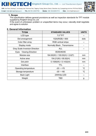
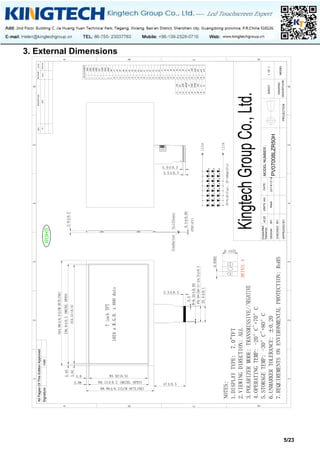
This document outlines the specifications for a 7.0-inch TFT module produced by Kingtech Group Co., Ltd., including details on dimensions, interfaces, electrical specifications, and reliability testing methods. It includes comprehensive sections on handling precautions, inspection standards, and warranty policies to ensure quality and performance. The document serves as a guide for the design, handling, and testing processes related to the TFT module to meet customer standards.


