Download to read offline
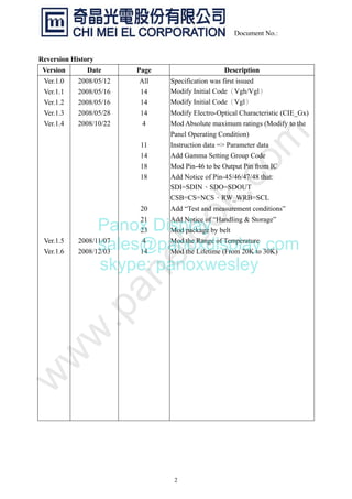
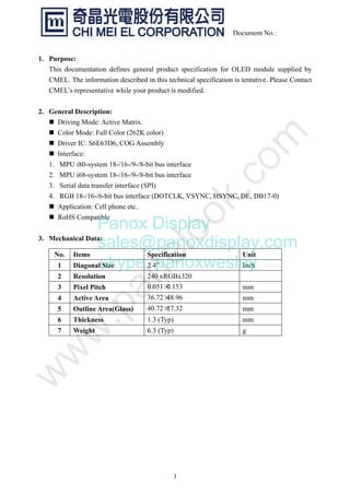
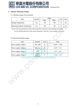
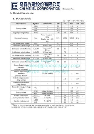
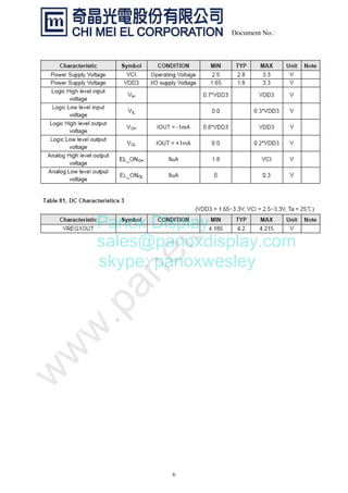
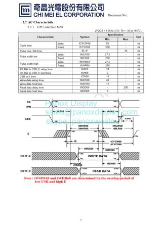
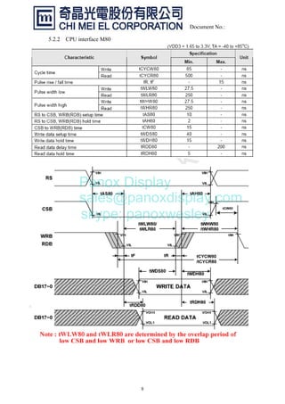
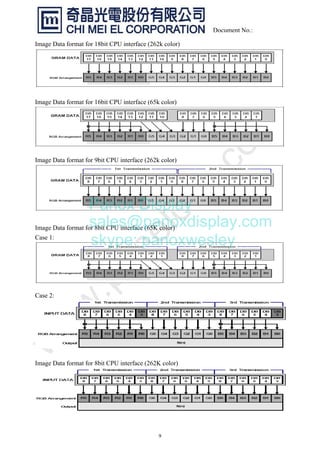
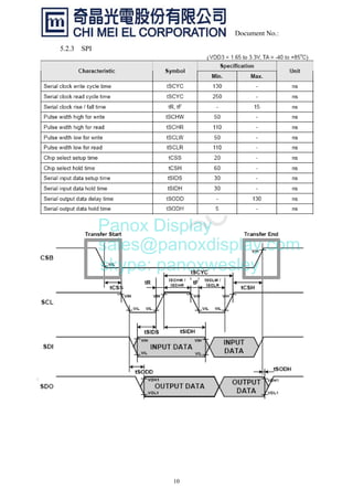
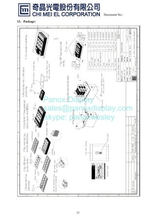

The document outlines the product specifications for the OLED module C0240QGLG-T, issued on December 3, 2008, including its maximum ratings, electrical characteristics, and mechanical dimensions. It emphasizes contacting Chi Mei El Corp for any design modifications and details the interfacing options available for various CPU types. Additionally, it includes testing procedures and handling instructions pertinent to the module's longevity and performance.