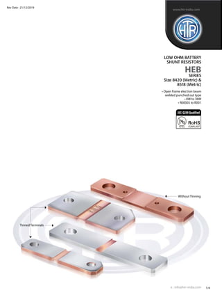
1. • Open frame electron beam
welded punched out type
• 6W to 36W
• R00005 to R001
LOW OHM BATTERY
SHUNT RESISTORS
HEB
SERIES
Size 8420 (Metric) &
8518 (Metric)
e : info@htr-india.com
www.htr-india.com
1/4
Rev Date : 21/12/2019
Tinned Terminals
Without Tinning
AEC-Q200Qualified
2. PHYSICAL CONFIGURATION
DIMENSIONAL TABLE
LOW OHM
BATTERY
SHUNT
RESISTORS
HEBSize
8420
(Metric) &
8518
(Metric)
e : info@htr-india.com
www.htr-india.com
A
F
CHAMPER 2x45˚ (TYP)
B
E
60±0.2
Cu
VOLTAGE TEST POINTCALIBRATION NOTCH -2mm (Ref)
Cu
C
D
Ø8.3
±0.1
Ø8.3
±0.1
APPLICATIONS
• Current sensor for EBM (Electronic Battery Management) in motorcars, trucks, forklifts, hybrid & electric vehicles.
• Current sensing in bus bars.
• Current sensing in welding equipments
FEATURES
• Upto 15W permanent power in free air.
• Continuous current load upto 350A (0.1 mohm)
• High pulse power rating.
• Maximum fastening torque 10Nm
• Shunt available with tinned or untinned terminals.
2/4
Rev Date : 21/12/2019
ELECTRICAL AND ENVIRONMENTAL CHARACTERISTICS
PARAMETER / PERFORMANCE TEST & TEST METHOD PERFORMANCE REQUIREMENTS
Power Rating For FeCrAl - Full power dissipation at 70° C and linearly derated to
zero at +170° C.
For Manganin (< 0.5% Improved Stability) -
Full power dissipation at 105° C & linearly derated to zero at +135° C.
For Manganin (< 1% Stability) - Full power dissipation at 140° C and
linearly derated to zero at +170° C.
Inductance < 1nH
ResistanceTolerance ± 1% (0.5% and other tolerance available on request)
Temperature Range - 40° C to +170° C
Voltage Rating / LimitingVoltage / Max.WorkingVoltage P x R
(Subject to max.TerminalTemperature of 120° C)
Temperature Coefficient of Resistance < 50 ppm / K (Depending on Resistance Value)
(AmbientTemperature Range 20° C - 60° C) For resistance values < 0.05 m ΩTCR on Request
LifeTest / Operational Life - 2000 h rated power with ∆R ± 1% - Average
Temperature limitation onTerminal kept at 120° C
Thermal EMV (0-60° C) 0.3µV/K
Internal heat resistance (Rthi) From 2°K/W
Dimensions as per Dimensions as per
size 8420 (Metric) size 8518 (Metric)
Sr No. Part No. A ± 0.20 B ± 0.1 C ± 0.5 D ± 0.2 E ± 0.3 F ± 0.10 C± 0.5 D± 0.2 E ± 0.3 F± 0.10
1 HEB36W R00005 J 2.2 3 5 8.2 84 20 4.5 7.7 85 18
2 HEB15W R0001 J 2.2 3 10 13.2 84 20 9 12.2 85 18
3 HEB8W R0002 J 2 3 18 21.2 84 20 16.5 19.7 85 18
4 HEB36W R00025 J 2 3 23 26.2 84 20 21 24.2 85 18
5 HEB7W R0005 J 2 3 14 17.2 84 20
6 HEB6W R001 J 2 3 28 31.2 84 20
7 HEB36W R000125 J 2 3 10.3 13.5 85 18
8 HEB36W R000035 J 2 3 4.8 8 84 20
Note : HEB6W R001 F have calibration notch from both side to achieve Resistance value
3. e : info@htr-india.com
PACKAGING
Resistors shall be packed in sealed plastic packets placed in small cardboard cartons
(Type‘A’Box ) of approximate size 200mmx150mmx70mm - 200pcs. & such 2 Boxes packed in Master Carton
of approximate size 310mmx205mmx95mm.
connection DIAGRAM
3/4
Rev Date : 21/12/2019
LOW OHM
BATTERY
SHUNT
RESISTORS
HEBSize
8420
(Metric) &
8518
(Metric)
www.htr-india.com
ordering information
SERIES TYPE PACKING RESISTANCE VALUE TOLERANCE
HEB HEB15W / HEB15W Bulk - HEB15W / HEB15W R0001 F
Storage Condition (Packed) : Temp 25°C to 35°C, Humidity 30 to 80% RH, Shelf life-12 months
Floor Life (Unpacked) : Temp 25°C to 35°C, Humidity 30 to 80% RH, Floor life-15 days
1. All types are RoHs compliant
2. For Tinned version - HEB15W-T
Position sense connection
for flexible wires
U
Soldering area
for pcb
I 1 I 2
MARKING
HTR PART NO PRINTING
HEB15W R0001 J HTR
R0001
5% DATECODE
4. 4/4
Rev Date : 21/12/2019
LOW OHM
BATTERY
SHUNT
RESISTORS
HEBSize
8420
(Metric) &
8518
(Metric)
www.htr-india.com
TYPICAL POWER DERATING CURVE FOR
RESISTOR WHEn full power is at 105° C & 140° C
TYPICAL POWER DERATING CURVE FOR
RESISTOR WHEn full power is at 70° C
Single pulse
Pulse power for continuous operation.
This curve is only valid for the resistance value R0001.
The shape of the curve in the range below 0.1 sec will be different for other resistance values.
In case the Design Engineer requires a specific graph of a particular component it can be supplied on request.
In case the Design Engineer requires a specific graph of a particular component it can be supplied on request.
Typical Temperature dependance of the electrical resistance
MAXIMUM PULSE ENERGY WITH RESPECT TO PULSE POWER FOR PERMANANT OPERATION
10000
1000
100
10
1
10000 1000
0.000
0.001
0.01
0.1
1
10
100
0.1
0.01
0.000001 0.00001 0.0001 0.001 0.01 0.1 1 10 100
Pulse width [sec]
Pulseenergy[J]
Power[W]
1
0.75
0.5
0.25
0
0 20 40 60 8070 100 120 140 160 180
1.25
Terminal Temperature [°C]
P/P 70 °C
1
0.75
0,5
0.25
0
0 20 40 60 80 100 120 140 160 180
1.25
Terminal Temperature [°C]
P/PNom
Stability <1.0%
Improved Stability <0.5%
-40
-1
1
0.8
0.6
0.4
0.2
0
-0.2
-0.4
-0.6
0.8
-20 0 20 40 60 80 100 120
Temperature [°C]
dR/R20 [%]
Limiting Curve
Typical temperature dependence of a HEB resistor
140
e : info@htr-india.com
5. • Open frame electron beam
welded punched out type
• 15W to 50W
• R00005 to R001
LOW OHM BATTERY
SHUNT RESISTORS
HEB
SERIES
Size 6018, 6315, 6918,
5520, 5216, 7036
e : info@htr-india.com
www.htr-india.com
1/4
Rev Date : 21/12/2019
Tinned Terminals
Without Tinning
AEC-Q200Qualified
6. PHYSICAL CONFIGURATION
DIMENSIONAL TABLE
LOW OHM
BATTERY
SHUNT
RESISTORS
HEBSize 6018,
6315, 6918,
5520, 5216,
7036
e : info@htr-india.com
www.htr-india.com
APPLICATIONS
• Current sensor for EBM (Electronic Battery Management) in motorcars, trucks, forklifts, hybrid & electric vehicles.
• Current sensing in bus bars.
• Current sensing in welding equipments
FEATURES
• Upto 15W permanent power in free air.
• Continuous current load upto 350A (0.1 mohm)
• High pulse power rating.
• Maximum fastening torque 10Nm
• Shunt available with tinned or untinned terminals.
2/4
Rev Date : 21/12/2019
ELECTRICAL AND ENVIRONMENTAL CHARACTERISTICS
PARAMETER / PERFORMANCE TEST & TEST METHOD PERFORMANCE REQUIREMENTS
Power Rating For FeCrAl - Full power dissipation at 70° C and linearly derated to
zero at +170° C.
For Manganin (< 0.5% Improved Stability) -
Full power dissipation at 105° C & linearly derated to zero at +135° C.
For Manganin (< 1% Stability) - Full power dissipation at 140° C and
linearly derated to zero at +170° C.
Inductance < 1nH
ResistanceTolerance ± 1% (0.5% and other tolerance available on request)
Temperature Range - 40° C to +170° C
Voltage Rating / LimitingVoltage / Max.WorkingVoltage P x R
(Subject to max.TerminalTemperature of 120° C)
Temperature Coefficient of Resistance < 50 ppm / K (Depending on Resistance Value)
(AmbientTemperature Range 20° C - 60° C) For resistance values < 0.05 m ΩTCR on Request
LifeTest / Operational Life - 2000 h rated power with ∆R ± 1% - Average
Temperature limitation onTerminal kept at 120° C
Thermal EMV (0-60° C) 0.3µV/K
Internal heat resistance (Rthi) From 2°K/W
A
F
CHAMPER 2x45˚ (TYP)
B
E
G
Cu
VOLTAGE TEST POINTCALIBRATION NOTCH -2mm (Ref)
Cu
C
D
Ød
2X
Sr No. HI-TECH PART NAME A ± 0.20 B ± 0.1 C ± 0.5 D ± 0.2 E ± 0.3 F±0.10 G± 0.1 Ød± 0.10 CHAMPER
1 HEB15W R0001 J (6018) 2 3 8.3 11.4 60 18 44 6.6 2X45 (3Place) 5X45 (1Place)
2 HEB15W R0001 J (5216) 2.2 3 8.1 11.2 52 16 33.7 6.6 1X45 (3Place) 3X45 (1Place)
3 HEB36W R000075 J (6315) 1.92 3 5 8.1 63 15.5 48 5 2X45 (3Place) 5X45 (1Place)
4 HEB36W R00005 J (6918) 2 3 4.5 6.6 69 18 52 6.6 2X45 (3Place) 5X45 (1Place)
5 HEB50W R00005 J (7036) 2 3 9.4 12.5 70 36 50 8.5 2X45 (3Place) 10X45 (1Place)
6 HEB15W R001 J (5520) 2.2 3 10 18.2 55 20 40 6.3
7. e : info@htr-india.com
PACKAGING
Resistors shall be packed in sealed plastic packets placed in small cardboard cartons
(Type‘A’Box ) of approximate size 200mmx150mmx70mm - 200pcs. & such 2 Boxes packed in Master Carton
of approximate size 310mmx205mmx95mm.
connection DIAGRAM
3/4
Rev Date : 21/12/2019
www.htr-india.com
ordering information
SERIES TYPE PACKING RESISTANCE VALUE TOLERANCE
HEB HEB15W / HEB15W Bulk - HEB15W / HEB15W R0001 J
Storage Condition (Packed) : Temp 25°C to 35°C, Humidity 30 to 80% RH, Shelf life-12 months
Floor Life (Unpacked) : Temp 25°C to 35°C, Humidity 30 to 80% RH, Floor life-15 days
1. All types are RoHs compliant
2. For Tinned version - HEB15W-T
Position sense connection
for flexible wires
U
Soldering area
for pcb
I 1 I 2
MARKING
HTR PART NO PRINTING
HEB15W R0001 J HTR
R0001
5% DATECODE
LOW OHM
BATTERY
SHUNT
RESISTORS
HEBSize 6018,
6315, 6918,
5520, 5216,
7036
8. 4/4
Rev Date : 13/12/2019
www.htr-india.com
TYPICAL POWER DERATING CURVE FOR
RESISTOR WHEn full power is at 105° C & 140° C
TYPICAL POWER DERATING CURVE FOR
RESISTOR WHEn full power is at 70° C
Single pulse
Pulse power for continuous operation.
This curve is only valid for the resistance value R0001.
The shape of the curve in the range below 0.1 sec will be different for other resistance values.
In case the Design Engineer requires a specific graph of a particular component it can be supplied on request.
In case the Design Engineer requires a specific graph of a particular component it can be supplied on request.
MAXIMUM PULSE ENERGY WITH RESPECT TO PULSE POWER FOR PERMANANT OPERATION
10000
1000
100
10
1
10000 1000
0.000
0.001
0.01
0.1
1
10
100
0.1
0.01
0.000001 0.00001 0.0001 0.001 0.01 0.1 1 10 100
Pulse width [sec]
Pulseenergy[J]
Power[W]
1
0.75
0.5
0.25
0
0 20 40 60 8070 100 120 140 160 180
1.25
Terminal Temperature [°C]
P/P 70 °C
1
0.75
0,5
0.25
0
0 20 40 60 80 100 120 140 160 180
1.25
Terminal Temperature [°C]
P/PNom
Stability <1.0%
Improved Stability <0.5%
e : info@htr-india.com
LOW OHM
BATTERY
SHUNT
RESISTORS
HEBSize 6018,
6315, 6918,
5520, 5216,
7036