This document defines standards for interfaces in optical transport networks. It specifies requirements for optical transport module signals, including optical transport hierarchy, overhead functionality, frame structures, bit rates, and client signal mapping formats. The standards support multiplexing of client signals and wavelength division multiplexing. The document has been revised multiple times to include additional amendments and support new client signals.

![Rec. ITU-T G.709/Y.1331 (02/2012) 1
Recommendation ITU-T G.709/Y.1331
Interfaces for the optical transport network
1 Scope
The optical transport hierarchy (OTH) supports the operation and management aspects of optical
networks of various architectures, e.g., point-to-point, ring and mesh architectures.
This Recommendation defines the interfaces of the optical transport network to be used within and
between subnetworks of the optical network, in terms of:
– optical transport hierarchy (OTH)
– functionality of the overhead in support of multi-wavelength optical networks
– frame structures
– bit rates
– formats for mapping client signals.
The interfaces defined in this Recommendation can be applied at user-to-network interfaces (UNI)
and network node interfaces (NNI) of the optical transport network. It is recognized, for interfaces
used within optical subnetworks, that aspects of the interface are optical technology dependent and
subject to change as technology progresses. Therefore, optical technology dependent aspects (for
transverse compatibility) are not defined for these interfaces to allow for technology changes. The
overhead functionality necessary for operations and management of optical subnetworks is defined.
The second revision of this Recommendation introduced:
– support for an extended (unlimited) set of constant bit rate client signals;
– a flexible ODUk, which can have any bit rate and a bit-rate tolerance up to ±100 ppm;
– a client/server independent generic mapping procedure to map a client signal into the
payload of an OPUk, or to map an ODUj signal into the payload of one or more tributary
slots in an OPUk;
– ODUk delay measurement capability.
The third revision of this Recommendation introduces the text of Amendments 1 and 2,
Corrigendum 1 and Erratum 1 to Recommendation ITU-T G.709/Y.1331 (2009) and support for
more client signals.
2 References
The following ITU-T Recommendations and other references contain provisions which, through
reference in this text, constitute provisions of this Recommendation. At the time of publication, the
editions indicated were valid. All Recommendations and other references are subject to revision;
users of this Recommendation are therefore encouraged to investigate the possibility of applying the
most recent edition of the Recommendations and other references listed below. A list of the
currently valid ITU-T Recommendations is regularly published. The reference to a document within
this Recommendation does not give it, as a stand-alone document, the status of a Recommendation.
[ITU-T G.652] Recommendation ITU-T G.652 (2009), Characteristics of a single-mode
optical fibre and cable.
[ITU-T G.653] Recommendation ITU-T G.653 (2006), Characteristics of a dispersion-
shifted single-mode optical fibre and cable.](https://image.slidesharecdn.com/dd175b1f-a76f-4140-ae81-1f3e866587da-160607171351/85/T-REC-G-709-201202-I-PDF-E-9-320.jpg)
![2 Rec. ITU-T G.709/Y.1331 (02/2012)
[ITU-T G.655] Recommendation ITU-T G.655 (2009), Characteristics of a non-zero
dispersion-shifted single-mode optical fibre and cable.
[ITU-T G.693] Recommendation ITU-T G.693 (2009), Optical interfaces for intra-office
systems.
[ITU-T G.695] Recommendation ITU-T G.695 (2009), Optical interfaces for coarse
wavelength division multiplexing applications.
[ITU-T G.707] Recommendation ITU-T G.707/Y.1322 (2003), Network node interface
for the synchronous digital hierarchy (SDH).
[ITU-T G.780] Recommendation ITU-T G.780/Y.1351 (2008), Terms and definitions for
synchronous digital hierarchy (SDH) networks.
[ITU-T G.798] Recommendation ITU-T G.798 (2006), Characteristics of optical
transport network hierarchy equipment functional blocks.
[ITU-T G.805] Recommendation ITU-T G.805 (2000), Generic functional architecture
of transport networks.
[ITU-T G.806] Recommendation ITU-T G.806 (2009), Characteristics of transport
equipment – Description methodology and generic functionality.
[ITU-T G.870] Recommendation ITU-T G.870/Y.1352 (2004), Terms and definitions for
optical transport networks (OTN).
[ITU-T G.872] Recommendation ITU-T G.872 (2001), Architecture of optical transport
networks.
[ITU-T G.873.1] Recommendation ITU-T G.873.1 (2006), Optical Transport Network
(OTN): Linear protection.
[ITU-T G.873.2] Recommendation ITU-T G.873.2 (2012), ODUk shared ring protection
(SRP).
[ITU-T G.959.1] Recommendation ITU-T G.959.1 (2009), Optical transport network
physical layer interfaces.
[ITU-T G.984.6] Recommendation ITU-T G.984.6 (2008), Gigabit-capable passive
optical networks (GPON): Reach extension.
[ITU-T G.987.4] Recommendation ITU-T G.987.4 (2012), 10 Gigabit-capable passive
optical networks (XG-PON): Reach extension.
[ITU-T G.7041] Recommendation ITU-T G.7041/Y.1303 (2003), Generic framing
procedure (GFP).
[ITU-T G.7042] Recommendation ITU-T G.7042/Y.1305 (2001), Link capacity
adjustment scheme (LCAS) for virtual concatenated signals.
[ITU-T G.7044] Recommendation ITU-T G.7044/Y.1347 (2011), Hitless Adjustment of
ODUflex(GFP).
[ITU-T G.7714.1] Recommendation ITU-T G.7714.1/Y.1705.1 (2010), Protocol for
automatic discovery in SDH and OTN networks.
[ITU-T G.8011.1] Recommendation ITU-T G.8011.1/Y.1307.1 (2009), Ethernet private
line service.
[ITU-T I.432.1] Recommendation ITU-T I.432.1 (1999), B-ISDN user-network
interface – Physical layer specification: General characteristics.](https://image.slidesharecdn.com/dd175b1f-a76f-4140-ae81-1f3e866587da-160607171351/85/T-REC-G-709-201202-I-PDF-E-10-320.jpg)
![Rec. ITU-T G.709/Y.1331 (02/2012) 3
[ITU-T M.1400] Recommendation ITU-T M.1400 (2001), Designations for
interconnections among operators' networks.
[ITU-T M.3100 Amd.3] Recommendation ITU-T M.3100 (1995) Amd.3 (2001), Generic network
information model − Amendment 3: Definition of the management
interface for a generic alarm reporting control (ARC) feature.
[ITU-T O.150] Recommendation ITU-T O.150 (1996), General requirements for
instrumentation for performance measurements on digital transmission
equipment.
[ITU-T T.50] Recommendation ITU-T T.50 (1992), International Reference Alphabet
(IRA) (Formely International Alphabet No. 5 or IA5) – Information
technology – 7-bit coded character set for information interchange.
[IEEE 802.3] IEEE Std. 802.3:2008, IEEE Standard for Information Technology –
Telecommunications and Information Exchange Between Systems –
Local and Metropolitan Area Networks – Specific Requirements Part 3:
Carrier Sense Multiple Access With Collision Detection (CSMA/CD)
Access Method and Physical Layer Specifications.
[IEEE 802.3ba] IEEE Std 802.3ba-2010, IEEE Standard for Information technology –
Telecommunications and information exchange between systems – Local
and metropolitan area networks – Specific requirements Part 3: Carrier
Sense Multiple Access with Collision Detection (CSMA/CD) Access
Method and Physical Layer Specifications Amendment 4: Media Access
Control Parameters, Physical Layers and Management Parameters for
40 Gb/s and 100 Gb/s Operation.
3 Definitions
3.1 Terms defined elsewhere
This Recommendation uses the following terms defined elsewhere:
3.1.1 Terms defined in [ITU-T G.780]:
– BIP-X
– network node interface
3.1.2 Terms defined in [ITU-T G.805]:
– adapted information (AI)
– characteristic information (CI)
– network
– subnetwork
3.1.3 Terms defined in [ITU-T G.870]:
– CBR10G
– CBR2G5
– CBR40G
– completely standardized OTUk (OTUk)
– connection monitoring end point (CMEP)
– functionally standardized OTUk (OTUkV)
– hitless activation/deactivation of a connection monitor](https://image.slidesharecdn.com/dd175b1f-a76f-4140-ae81-1f3e866587da-160607171351/85/T-REC-G-709-201202-I-PDF-E-11-320.jpg)
![4 Rec. ITU-T G.709/Y.1331 (02/2012)
– inter-domain interface (IrDI)
– intra-domain interface (IaDI)
– link capacity adjustment scheme (LCAS)
– non associated overhead (naOH)
– OCC with full functionality (OCC)
– OCC with reduced functionality (OCCr)
– OCG with full functionality (OCG n)
– OCG with reduced functionality (OCG nr)
– ODUk path (ODUkP)
– ODUk TCM (ODUkT)
– optical carrier group of order n (OCG n[r])
– optical channel (OCh[r])
– optical channel carrier (OCC[r])
– optical channel data unit (ODUk)
– optical channel payload unit (OPUk)
– optical channel transport unit (OTUk[V])
– optical channel with full functionality (OCh)
– optical channel with reduced functionality (OChr)
– optical multiplex unit (OMU n, n ≥ 1)
– optical physical section of order n (OPSn)
– optical supervisory channel (OSC)
– optical transport hierarchy (OTH)
– optical transport module (OTM n[r].m)
– optical transport network (OTN)
– optical transport network node interface (ONNI)
– OTH multiplexing
– OTM overhead signal (OOS)
– OTM with full functionality (OTM n.m)
– OTM with reduced functionality (OTM-0.m, OTM-nr.m)
3.1.4 Terms defined in [ITU-T G.872]:
– optical multiplex section (OMS)
– optical transmission section (OTS)
3.2 Terms defined in this Recommendation
This Recommendation defines the following terms:
3.2.1 ODUk.ts: The ODUk.ts is an increment of bandwidth which when multiplied by a number
of tributary slots gives the recommended size of an ODUflex(GFP) optimized to occupy a given
number of tributary slots of a higher order OPUk.](https://image.slidesharecdn.com/dd175b1f-a76f-4140-ae81-1f3e866587da-160607171351/85/T-REC-G-709-201202-I-PDF-E-12-320.jpg)
![Rec. ITU-T G.709/Y.1331 (02/2012) 9
Sk Sink
SM Section Monitoring
SMOH Section Monitoring Overhead
SNC Subnetwork Connection
SNC/I Subnetwork Connection protection with Inherent monitoring
SNC/N Subnetwork Connection protection with Non-intrusive monitoring
SNC/S Subnetwork Connection protection with Sublayer monitoring
So Source
SQ Sequence Indicator
TC Tandem Connection
TC-CMEP Tandem Connection-Connection Monitoring End Point
TCM Tandem Connection Monitoring
TCMOH Tandem Connection Monitoring Overhead
TS Tributary Slot
TSOH Tributary Slot Overhead
TTT Timing Transparent Transcoding
TxTI Transmitted Trace Identifier
UNI User-to-Network Interface
VCG Virtual Concatenation Group
VCOH Virtual Concatenation Overhead
vcPT virtual concatenated Payload Type
XGPON 10 Gigabit-capable Passive Optical Networks
5 Conventions
This Recommendation uses the following conventions defined in [ITU-T G.870]:
– k
– m
– n
– r.
The functional architecture of the optical transport network as specified in [ITU-T G.872] is used to
derive the ONNI. The ONNI is specified in terms of the adapted and characteristic information
present in each layer as described in [ITU-T G.805].
Transmission order: The order of transmission of information in all the diagrams in this
Recommendation is first from left to right and then from top to bottom. Within each byte the most
significant bit is transmitted first. The most significant bit (bit 1) is illustrated at the left in all the
diagrams.
Mapping order: The serial bit stream of a constant bit rate signal is inserted into the OPU payload
so that the bits will be transmitted on the OPU/ODU in the same order that they were received at the
input of the AMP, BMP or GMP mapper function. If m bits ba, bb, bc up to bm are client signal bits
of which ba is the bit that is received first and bm is the bit that is received last, then ba will be](https://image.slidesharecdn.com/dd175b1f-a76f-4140-ae81-1f3e866587da-160607171351/85/T-REC-G-709-201202-I-PDF-E-17-320.jpg)
![10 Rec. ITU-T G.709/Y.1331 (02/2012)
mapped into bit 1 of a first OPU byte and bm will be mapped into bit 8 of an nth
OPU byte (with
n = m/8).
Value of reserved bit(s): The value of an overhead bit, which is reserved or reserved for future
international standardization shall be set to "0".
Value of non-sourced bit(s): Unless stated otherwise, any non-sourced bits shall be set to "0".
OTUk, ODUk and OPUk overhead assignment: The assignment of an overhead in the optical
channel transport/data/payload unit signal to each part is defined in Figure 5-1.
. . ....
G.709-Y.1331(12)_F5-1
Row#
Column #
Frame alignment area OTU specific overhead area
ODU specific overhead area
OPU
specific
overheadarea
1
2
3
4
1 167 14 158
Figure 5-1 − OTUk, ODUk and OPUk overhead
6 Optical transport network interface structure
The optical transport network as specified in [ITU-T G.872] defines two interface classes:
• inter-domain interface (IrDI)
• intra-domain interface (IaDI).
The OTN IrDI interfaces are defined with 3R processing at each end of the interface.
The optical transport module-n (OTM-n) is the information structure used to support OTN
interfaces. Two OTM-n structures are defined:
• OTM interfaces with full functionality (OTM-n.m)
• OTM interfaces with reduced functionality (OTM-0.m, OTM-nr.m, OTM-0.mvn).
The reduced functionality OTM interfaces are defined with 3R processing at each end of the
interface to support the OTN IrDI interface class.
6.1 Basic signal structure
The basic structure is shown in Figure 6-1.](https://image.slidesharecdn.com/dd175b1f-a76f-4140-ae81-1f3e866587da-160607171351/85/T-REC-G-709-201202-I-PDF-E-18-320.jpg)
![Rec. ITU-T G.709/Y.1331 (02/2012) 11
G.709-Y.1331(12)_F6-1
Clients (e.g., STM-N, ATM, IP, Ethernet, MPLS, ...)
HO OPUk
LO OPUk
ODUkP
ODUkP
ODUkT
ODUkT
HO ODUk
LO ODUk
OTUkV OTUk OTUkV OTUk OTUk
O hrC
OPSMnk
OPSn
OMSn
OTSn
OCh
OCh
substructure
OTM-n.m
OTM-n.m
OTM-0.m,
OTM-nr.m
OTM-0.m,
OTM-nr.m
Full
functionality
OTM interface
Full
functionality
OTM interface
Reduced
functionality
OTM interface
Reduced
functionality
OTM interface
OTM-0.mvn
OTM-0.mvn
Multi-lane,
reduced
functionality
OTM interface
Multi-lane,
reduced
functionality
OTM interface
OTUkV OTUk
OMSn
OTSn
OCh
OTUkV OTUk
O hrC
OPSn
OTUk
OPSMnk
Figure 6-1 − Structure of the OTN interfaces
6.1.1 OCh substructure
The optical channel layer as defined in [ITU-T G.872] is further structured in layer networks in
order to support the network management and supervision functionalities defined in [ITU-T G.872]:
– The optical channel with full (OCh) or reduced functionality (OChr), which provides
transparent network connections between 3R regeneration points in the OTN.
– The completely or functionally standardized optical channel transport unit (OTUk/OTUkV)
which provides supervision and conditions the signal for transport between 3R regeneration
points in the OTN.
– The optical channel data unit (ODUk) which provides:
• tandem connection monitoring (ODUkT)
• end-to-end path supervision (ODUkP)
• adaptation of client signals via the optical channel payload unit (OPUk)
• adaptation of OTN ODUk signals via the optical channel payload unit (OPUk).
6.1.2 Full functionality OTM-n.m (n ≥ 1) structure
The OTM-n.m (n ≥ 1) consists of the following layers:
• optical transmission section (OTSn)
• optical multiplex section (OMSn)
• full functionality optical channel (OCh)
• completely or functionally standardized optical channel transport unit (OTUk/OTUkV)
• one or more optical channel data unit (ODUk).
6.1.3 Reduced functionality OTM-nr.m and OTM-0.m structure
The OTM-nr.m and OTM-0.m consist of the following layers:
• optical physical section (OPSn)](https://image.slidesharecdn.com/dd175b1f-a76f-4140-ae81-1f3e866587da-160607171351/85/T-REC-G-709-201202-I-PDF-E-19-320.jpg)
![12 Rec. ITU-T G.709/Y.1331 (02/2012)
• reduced functionality optical channel (OChr)
• completely or functionally standardized optical channel transport unit (OTUk/OTUkV)
• one or more optical channel data unit (ODUk).
6.1.4 Parallel OTM-0.mvn structure
The OTM-0.mvn consists of the following layers:
• optical physical section (OPSMnk)
• completely standardized optical channel transport unit (OTUk)
• one or more optical channel data unit (ODUk).
6.2 Information structure for OTN interfaces
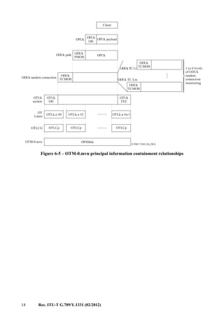
The information structure for OTN interfaces is represented by information containment
relationships and flows. The principal information containment relationships are described in
Figures 6-2, 6-3, 6-4 and 6-5. The information flows are illustrated in Figure 6-6.
For supervision purposes in the OTN, the OTUk/OTUkV signal is terminated whenever the
OCh signal is terminated.
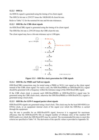
......
G.709-Y.1331(12)_F6-2
...
Client
OPUk payloadOPUk
OH
OPUkODUk path
OPUk
ODUk
PMOH
ODUk
TCMOH
ODUk tandem connection
OTUk[V]
OH
OTUk[V]
FEC
OTUk[V]
section
ODUk
TCMOH
ODUk
TCMOHODUkTCL1
ODUk TC Lm
OCh payload
OCCp OCCpOCCpOCCp OCCp
OCh
OHOCh
OCG-n.m
OTM-n.m
OCCo
OCCo
OCCo
OCCo
OCCo
OMU-n.m OMSn payload
OTSn payload
OOS
OTSn
OH
OMSn
OH
OTMCOMMs
1 to 6 levels
of ODUk
tandem
connection
monitoring
Figure 6-2 – OTM-n.m principal information containment relationships](https://image.slidesharecdn.com/dd175b1f-a76f-4140-ae81-1f3e866587da-160607171351/85/T-REC-G-709-201202-I-PDF-E-20-320.jpg)
![Rec. ITU-T G.709/Y.1331 (02/2012) 13
G.709-Y.1331(12)_F6-3
...
Client
OPUk payloadOPUk
OH
OPUkODUk path
OPUk
ODUk
PMOH
ODUk
TCMOH
ODUk tandem connection
OTUk[V]
OH
OTUk[V]
FEC
OTUk[V]
section
ODUk
TCMOH
ODUk
TCMOH
ODUkTC L1
ODUk TC Lm
OCh payload
OPS0
OChr
OTM-0.m
1 to 6 levels
of ODUk
tandem
connection
monitoring
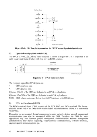
Figure 6-3 – OTM-0.m principal information containment relationships
...
G.709-Y.1331(12)_F6-4
...
Client
OPUk payload
OPUk
OH
OPUkODUk path
OPUk
ODUk
PMOH
ODUk
TCMOH
ODUk tandem connection
OTUk[V]
OH
OTUk[V]
FEC
OTUk[V]
section
ODUk
TCMOH
ODUk
TCMOHODUkTC L1
ODUk TC Lm
OCh payload
OCCp OCCpOCCpOCCp OCCp
OChr
OTM-nr.m OPSn
1 to 6 levels
of ODUk
tandem
connection
monitoring
Figure 6-4 – OTM-nr.m principal information containment relationships](https://image.slidesharecdn.com/dd175b1f-a76f-4140-ae81-1f3e866587da-160607171351/85/T-REC-G-709-201202-I-PDF-E-21-320.jpg)
![16 Rec. ITU-T G.709/Y.1331 (02/2012)
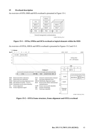
7 Multiplexing/mapping principles and bit rates
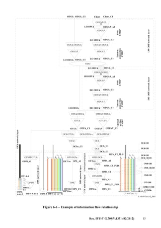
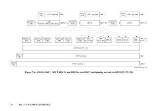
Figures 7-1A and 7-1B show the relationship between various information structure elements and
illustrate the multiplexing structure and mappings (including wavelength and time division
multiplexing) for the OTM-n. In the multi-domain OTN any combination of the ODUk
multiplexing layers may be present at a given OTN NNI. The interconnection of and visibility of
ODUk multiplexing layers within an equipment or domain is outside the scope of this
Recommendation. Refer to [ITU-T G.872] for further information on interconnection of and
multiplexing of ODUk layers within a domain. Figure 7-1A shows that a (non-OTN) client signal is
mapped into a lower order OPU, identified as "OPU (L)". The OPU (L) signal is mapped into the
associated lower order ODU, identified as "ODU (L)". The ODU (L) signal is either mapped into
the associated OTU[V] signal, or into an ODTU. The ODTU signal is multiplexed into an ODTU
Group (ODTUG). The ODTUG signal is mapped into a higher order OPU, identified as "OPU (H)".
The OPU (H) signal is mapped into the associated higher order ODU, identified as "ODU (H)". The
ODU (H) signal is mapped into the associated OTU[V].
The OPU (L) and OPU (H) are the same information structures, but with different client signals.
The concepts of lower order and high order ODU are specific to the role that the ODU plays within
a single domain.
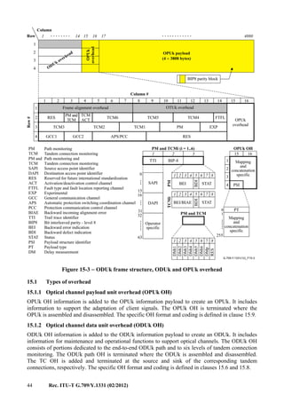
Figure 7-1B shows that an OTU[V] signal is mapped either into an optical channel signal, identified
as OCh and OChr, or into an OTLk.n. The OCh/OChr signal is mapped into an optical channel
carrier, identified as OCC and OCCr. The OCC/OCCr signal is multiplexed into an OCC group,
identified as OCG-n.m and OCG-nr.m. The OCG-n.m signal is mapped into an OMSn. The OMSn
signal is mapped into an OTSn. The OTSn signal is presented at the OTM-n.m interface. The
OCG-nr.m signal is mapped into an OPSn. The OPSn signal is presented at the OTM-nr.m
interface. A single OCCr signal is mapped into an OPS0. The OPS0 signal is presented at the
OTM-0.m interface. The OTLk.n signal is mapped into an optical transport lane carrier, identified
as OTLC. The OTLC signal is multiplexed into an OTLC group, identified as OTLCG. The
OTLCG signal is mapped into an OPSMnk. The OPSMnk signal is presented at the OTM-0.mvn
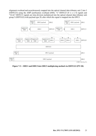
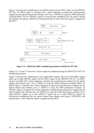
interface.](https://image.slidesharecdn.com/dd175b1f-a76f-4140-ae81-1f3e866587da-160607171351/85/T-REC-G-709-201202-I-PDF-E-24-320.jpg)
![Rec. ITU-T G.709/Y.1331 (02/2012) 17
G.709-Y.1331(12)_F7.1A
ODU4
OTU4[V]
× 1
× 1
ODU4
ODU4
(L)
ODU4
(H)
× 1
× 1
OPU4
(L)
OPU4
(H)
× 1
× 1
ODTUG4
PT = 21
× 80
× 40
× 10
× 2
× 80/ts
ODTU4.1
ODTU4.2
ODTU4.8
ODTU4.31
ODTU4.ts
ODU0
ODU1
ODU2
ODU2e
Client signal
Client signal
Client signal
ODU3
ODUflex
Client signal
Client signal
Client signal
Client signal
Client signal
Client signal
Client signal
ODU1
ODU2
ODU0
ODU2e
ODUflex
ODTU13
ODTU23
ODTU3.1
ODTU3.9
ODTU3.ts
ODTU13
ODTU23
× 16
× 32/ts
× 4
× 32
× 3
× 16
× 4
ODTUG3
PT = 21
ODTUG3
PT = 20
OPU3-X
× 1
× 1
× 1
× 1/X
× 1
× 1
× 1
× 1
OPU3
(H)
OPU3
(L)
ODU3
(H)
ODU3
(L)
OTU3[V]
ODU3
to ODU (H)
ODU3
to ODU (H)
ODU1
ODU2
ODU1
ODU0
ODUflex
ODU1
ODTU12
ODTU2.1
ODTU2.ts
× 4
× 8
× 8/ts
× 4
ODTUG2
PT = 21
ODTUG2
PT = 20
ODTUG1
PT = 20
× 1
× 1
× 1
× 1
× 1/X
ODU2e
(L)
OPU2-X
OPU2e
(L)
OPU2
(L)
ODU2
(L)
ODU2
(H)
OPU2
(H)
ODU2
to ODU (H)
ODU2
to ODU (H)
ODU2e
to ODU (H)
OTU2[V]
SeeFigure7-1B
ODU1
to ODU (H)
OTU1[V]
× 1
× 1
× 1
× 1
× 1
× 1/X
ODU1
to ODU (H)
ODU1
(L)
ODU1
(H)
OPU1
(H)
OPU1
(L)
OPU1-X
ODTU12
ODTU01
× 2
ODU0
OPUflex
(L)
OPU0
(L)
× 1
× 1
× 1
ODU0
to ODU (H)
ODUflex
to ODU (H)
ODU0
(L)
ODUflex
(L)
Multiplexing Mapping
Figure 7-1A – OTM multiplexing and mapping structures (Part I)](https://image.slidesharecdn.com/dd175b1f-a76f-4140-ae81-1f3e866587da-160607171351/85/T-REC-G-709-201202-I-PDF-E-25-320.jpg)
![18 Rec. ITU-T G.709/Y.1331 (02/2012)
G.709-Y.1331(12)_F7-1B
OTM-0.mvn OPSMn4
OPSMn3
OPS0OTM-0.m
× 1
× 1
× 1
× n
× n
× 1
× 1
× 1
× 1/n
× 1/n
× 1
× 1
× 1× 1
× 1
OPSnOTM-nr.m
OTM-n.m
× 1
× 1
× 1
× 1
× 1
× 1
× 1
× 1× 1
× 1
× 1
OTLCG
OTLCG
OTLC
OTLC
OCCr
OCCr
OCCr
OChr
× 1
× 1
OChr
OChr
OCh
OCh
OCh
OCh
OCCr
OCC
OCC
OCC
OCC
OTSn OMSn
OTS OH OMS OH
OSC
1 i j k l n≤ + + + ≤
× l
1 i j k l n≤ + + + ≤
OCG-nr.m
OCG-n.m
OChr
OTL4.n
OTL3.n
OTU4[V]
OTU3[V]
OTU2[V]
OTU1[V]
SeeFigure7-1A
OTM overhead signal (OOS)
OCh OH
COMMS OH
Multiplexing Mapping
× l
× j
× k
× l
× i
× j
× k
× i
Figure 7-1B – OTM multiplexing and mapping structures (Part II)
The OTS, OMS, OCh and COMMS overhead is inserted into the OOS using mapping and
multiplexing techniques which are outside the scope of this Recommendation.
7.1 Mapping
The client signal or an optical channel data tributary unit group (ODTUGk) is mapped into the
OPUk. The OPUk is mapped into an ODUk and the ODUk is mapped into an OTUk[V]. The
OTUk[V] is mapped into an OCh[r] and the OCh[r] is then modulated onto an OCC[r]. The OTUk
may also be mapped into n OTLk.n and an OTLk.n is then modulated onto an OTLC.](https://image.slidesharecdn.com/dd175b1f-a76f-4140-ae81-1f3e866587da-160607171351/85/T-REC-G-709-201202-I-PDF-E-26-320.jpg)
![Rec. ITU-T G.709/Y.1331 (02/2012) 19
7.2 Wavelength division multiplex
Up to n (n ≥ 1) OCC[r] are multiplexed into an OCG-n[r].m using wavelength division
multiplexing. The OCC[r] tributary slots of the OCG-n[r].m can be of different size.
The OCG-n[r].m is transported via the OTM-n[r].m. For the case of the full functionality OTM-n.m
interfaces the OSC is multiplexed into the OTM-n.m using wavelength division multiplexing.
n OTLC are aggregated into an OTLCG using wavelength division multiplexing. The OTLCG is
transported via the OTM-0.mvn.
7.3 Bit rates and capacity
The bit rates and tolerance of the OTUk signals are defined in Table 7-1.
The bit rates and tolerance of the ODUk signals are defined in clause 12.2 and Table 7-2.
The bit rates and tolerance of the OPUk and OPUk-Xv payload are defined in Table 7-3.
The OTUk/ODUk/OPUk/OPUk-Xv frame periods are defined in Table 7-4.
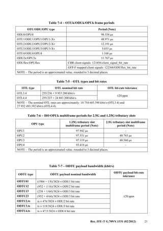
The types and bit rates of the OTLk.n signals are defined in Table 7-5.
The 2.5G and 1.25G tributary slot related HO OPUk multiframe periods are defined in Table 7-6.
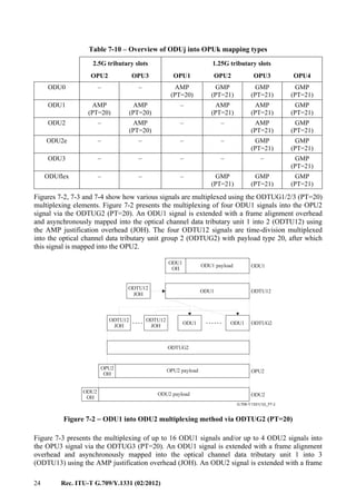
The ODTU payload area bandwidths are defined in Table 7-7. The bandwidth depends on the HO
OPUk type (k=1,2,3,4) and the mapping procedure (AMP or GMP). The AMP bandwidths include
the bandwidth provided by the NJO overhead byte. GMP is defined without such NJO bytes.
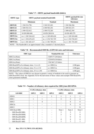
The bit rates and tolerance of the ODUflex(GFP) are defined in Table 7-8.
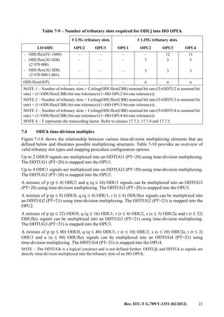
The number of HO OPUk tributary slots required by LO ODUj are summarized in Table 7-9.
Table 7-1 − OTU types and bit rates
OTU type OTU nominal bit rate OTU bit-rate tolerance
OTU1 255/238 × 2 488 320 kbit/s
±20 ppm
OTU2 255/237 × 9 953 280 kbit/s
OTU3 255/236 × 39 813 120 kbit/s
OTU4 255/227 × 99 532 800 kbit/s
NOTE 1 – The nominal OTUk rates are approximately: 2 666 057.143 kbit/s (OTU1),
10 709 225.316 kbit/s (OTU2), 43 018 413.559 kbit/s (OTU3) and 111 809 973.568 kbit/s (OTU4).
NOTE 2 – OTU0, OTU2e and OTUflex are not specified in this Recommendation. ODU0 signals are to be
transported over ODU1, ODU2, ODU3 or ODU4 signals, ODU2e signals are to be transported over ODU3
and ODU4 signals and ODUflex signals are transported over ODU2, ODU3 and ODU4 signals.
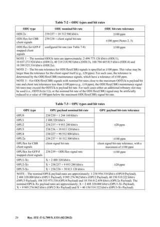
Table 7-2 − ODU types and bit rates
ODU type ODU nominal bit rate ODU bit-rate tolerance
ODU0 1 244 160 kbit/s
±20 ppm
ODU1 239/238 × 2 488 320 kbit/s
ODU2 239/237 × 9 953 280 kbit/s
ODU3 239/236 × 39 813 120 kbit/s
ODU4 239/227 × 99 532 800 kbit/s](https://image.slidesharecdn.com/dd175b1f-a76f-4140-ae81-1f3e866587da-160607171351/85/T-REC-G-709-201202-I-PDF-E-27-320.jpg)

![Rec. ITU-T G.709/Y.1331 (02/2012) 31
8 Optical transport module (OTM-n.m, OTM-nr.m, OTM-0.m, OTM-0.mvn)
Two OTM structures are defined, one with full functionality and one with reduced functionality.
For the IrDI only reduced functionality OTM interfaces are currently defined. Other full or reduced
functionality OTM IrDIs are for further study.
Table 8-1 provides an overview of the OTU, OTU FEC, OCh/OChr, OPS, OPSM and OMS/OTS
elements in the OTM structures specified in this clause.
Table 8-1 – Overview of OTM structures
OTUk
frame
OTUkV
frame
OTUk
FEC
OTUkV
FEC
OChr OCh OPS OPSM
OMS
OTS
IaDI IrDI
OTM-n.m X X X X X
OTM-n.m X X X X X
OTM-n.m X X X X X
OTM-
16/32r.m
X X X X X X
OTM-
16/32r.m
X X X X X
OTM-
16/32r.m
X X X X X
OTM-0.m X X X X X X
OTM-0.m X X X X X
OTM-
0.mvn
X X X X X
8.1 OTM with reduced functionality (OTM-0.m, OTM-nr.m, OTM-0.mvn)
The OTM-n supports n optical channels on a single optical span with 3R regeneration and
termination of the OTUk[V] on each end. As 3R regeneration is performed on both sides of the
OTM-0.m, OTM-nr.m and OTM-0.mvn interfaces access to the OTUk[V] overhead is available and
maintenance/supervision of the interface is provided via this overhead. Therefore a non-associated
OTN overhead is not required across the OTM-0.m, OTM-nr.m and OTM-0.mvn interfaces and an
OSC/OOS is not supported.
Three OTM interfaces classes with reduced functionality are defined, OTM-0.m, OTM-nr.m and
OTM-0.mvn. Other reduced functionality interfaces classes are for further study.
8.1.1 OTM-0.m
The OTM-0.m supports a non-coloured optical channel on a single optical span with 3R
regeneration at each end.
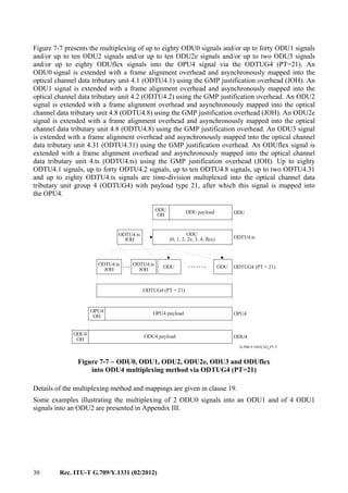
Four OTM-0.m interface signals (see Figure 8-1) are defined, each carrying a single channel optical
signal containing one OTUk[V] signal:
− OTM-0.1 (carrying an OTU1[V])
− OTM-0.2 (carrying an OTU2[V])
− OTM-0.3 (carrying an OTU3[V])
− OTM-0.4 (carrying an OTU4[V]).
In generic terms: OTM-0.m.](https://image.slidesharecdn.com/dd175b1f-a76f-4140-ae81-1f3e866587da-160607171351/85/T-REC-G-709-201202-I-PDF-E-39-320.jpg)
![32 Rec. ITU-T G.709/Y.1331 (02/2012)
G.709-Y.1331(12)_F8-1
Mapping
OTM-0.4
OTM-0.3
OTM-0.2
OTM-0.1
OCCr
OCCr
OCCr
OCCr
OChr
OChr
OChr
OChr
× 1
× 1
× 1
× 1
OTU4[V]
OTU3[V]
OTU2[V]
OTU1[V]
ODU4
ODU3
ODU2
ODU1
OPU4
OPU3
OPU2
OPU1
× 1
× 1
× 1
× 1
× 1
× 1
× 1
× 1
× 1
× 1
× 1
× 1
Figure 8-1 − OTM-0.m structure
Figure 8-1 shows the relationship between various information structure elements that are defined
below and illustrates possible mappings for the OTM-0.m.
An OSC is not present and there is no OOS either.
8.1.2 OTM-nr.m
8.1.2.1 OTM-16r.m
This OTM-16r.m supports 16 optical channels on a single optical span with 3R regeneration at each
end.
Several OTM-16r interface signals are defined. Some examples:
− OTM-16r.1 (carrying i (i ≤ 16) OTU1[V] signals);
− OTM-16r.2 (carrying j (j ≤ 16) OTU2[V] signals);
− OTM-16r.3 (carrying k (k ≤ 16) OTU3[V] signals);
− OTM-16r.4 (carrying l (l ≤ 16) OTU4[V] signals);
− OTM-16r.1234 (carrying i (i ≤ 16) OTU1[V], j (j ≤ 16) OTU2[V], k (k ≤ 16) OTU3[V] and
l (l ≤ 16) OTU4[V] signals with i + j + k +l ≤ 16);
− OTM-16r.123 (carrying i (i ≤ 16) OTU1[V], j (j ≤ 16) OTU2[V] and k (k ≤ 16) OTU3[V]
signals with i + j + k ≤ 16);
− OTM-16r.12 (carrying i (i ≤ 16) OTU1[V] and j (j ≤ 16) OTU2[V] signals with i + j ≤ 16);
− OTM-16r.23 (carrying j (j ≤ 16) OTU2[V] and k (k ≤ 16) OTU3[V] signals with
j + k ≤ 16);
− OTM-16r.34 (carrying k (k ≤ 16) OTU3[V] and l (l ≤ 16) OTU4[V] signals with
k + l ≤ 16);
which in generic terms are identified as OTM-16r.m.
The OTM-16r.m signal is an OTM-nr.m signal (see Figure 6-6) with 16 optical channel carriers
(OCCr) numbered OCCr #0 to OCCr #15. An optical supervisory channel (OSC) is not present and
there is no OOS either.
At least one of the OCCrs is in service during normal operation and transporting an OTUk[V].
There is no predefined order in which the OCCrs are taken into service.
Some examples of the defined OTM-16r.m interface signals and the OTM-16r.m multiplexing
structure are shown in Figure 8-2.](https://image.slidesharecdn.com/dd175b1f-a76f-4140-ae81-1f3e866587da-160607171351/85/T-REC-G-709-201202-I-PDF-E-40-320.jpg)
![Rec. ITU-T G.709/Y.1331 (02/2012) 33
NOTE – OTM-16r.m OPS overhead is not defined. The interface will use the OTUk[V] SMOH in this
multi-wavelength interface for supervision and management. OTM-16r.m connectivity (TIM) failure reports
will be computed from the individual OTUk[V] reports by means of failure correlation in fault management.
Refer to the equipment Recommendations for further details.
G.709-Y.1331(12)_F8-2
Multiplexing Mapping
OTM-16r.1
OTM-16r.2
OTM-16r.3
OTM-16r.12
OTM-16r.23
OTM-16r.123
OCG-16r.1
OCG-16r.2
OCG-16r.3
OCG-16r.12
OCG-16r.23
OCG-16r.123
OCCr
OCCr
OCCr
OCCr
OCCr
OCCr
OCCr
OCCr
OCCr
OCCr
OChr
OChr
OChr
OChr
OChr
OChr
OChr
OChr
OChr
OChr
× 1
× 1
× 1
× 1
× 1
× 1
× 1
× 1
× 1
× 1
OTU1[V]
OTU2[V]
OTU3[V]
OTU2[V]
OTU1[V]
OTU3[V]
OTU2[V]
OTU3[V]
OTU2[V]
OTU1[V]
ODU1
ODU2
ODU3
ODU2
ODU1
ODU3
ODU2
ODU3
ODU2
ODU1
OPU1
OPU2
OPU3
OPU2
OPU1
OPU3
OPU2
OPU3
OPU2
OPU1
× 1
× 1
× 1
× 1
× 1
× 1
× 1
× 1
× 1
× 1
× 1
× 1
× 1
× 1
× 1
× 1
× i
× j
× k
× j
× 1
× 1
× 1
× 1
× 1
× 1
× 1
× 1
× 1
× 1
× 1
× 1
× 1
× 1
× 1
× 1
× 1
× 1
× 1
× 1
Client
signal
Client
signal
Client
signal
Client
signal
Client
signal
Client
signal
Client
signal
Client
signal
Client
signal
Client
signal
1 i 16≤ ≤
1 j 16≤ ≤
1 k 16≤ ≤
1 i + j 16≤ ≤
1 j + k 16≤ ≤
1 i + j + k 16≤ ≤
× i
× i
× k
× k
× j
× j
Figure 8-2 − OTM-16r.m multiplexing structure examples
8.1.2.2 OTM-32r.m
This OTM-32r.m supports 32 optical channels on a single optical span with 3R regeneration at each
end.
Several OTM-32r interface signals are defined. Some examples:
− OTM-32r.1 (carrying i (i ≤ 32) OTU1[V] signals);
− OTM-32r.2 (carrying j (j ≤ 32) OTU2[V] signals);
− OTM-32r.3 (carrying k (k ≤ 32) OTU3[V] signals);
− OTM-32r.4 (carrying l (l ≤ 32) OTU4[V] signals);
− OTM-32r.1234 (carrying i (i ≤ 32) OTU1[V], j (j ≤ 32) OTU2[V], k (k ≤ 32) OTU3[V] and
l (l ≤ 32) OTU4[V] signals with i + j + k + l ≤ 32);](https://image.slidesharecdn.com/dd175b1f-a76f-4140-ae81-1f3e866587da-160607171351/85/T-REC-G-709-201202-I-PDF-E-41-320.jpg)
![34 Rec. ITU-T G.709/Y.1331 (02/2012)
− OTM-32r.123 (carrying i (i ≤ 32) OTU1[V], j (j ≤ 32) OTU2[V] and k (k ≤ 32) OTU3[V]
signals with i + j + k ≤ 32);
− OTM-32r.12 (carrying i (i ≤ 32) OTU1[V] and j (j ≤ 32) OTU2[V] signals with i + j ≤ 32);
− OTM-32r.23 (carrying j (j ≤ 32) OTU2[V] and k (k ≤ 32) OTU3[V] signals with
j + k ≤ 32);
− OTM-32r.34 (carrying k (k ≤ 32) OTU3[V] and l (l ≤ 32) OTU4[V] signals with
k + l ≤ 32);
which in generic terms are identified as OTM-32r.m.
The OTM-32r.m signal is an OTM-nr.m signal (see Figure 6-6) with 32 optical channel carriers
(OCCr) numbered OCCr #0 to OCCr #31. An optical supervisory channel (OSC) is not present and
there is no OOS either.
At least one of the OCCrs is in service during normal operation and transporting an OTUk[V].
There is no predefined order in which the OCCrs are taken into service.
NOTE – OTM-32r.m OPS overhead is not defined. The interface will use the OTUk[V] SMOH in this
multi-wavelength interface for supervision and management. OTM-32r.m connectivity (TIM) failure reports
will be computed from the individual OTUk[V] reports by means of failure correlation in fault management.
Refer to the equipment Recommendations for further details.
8.1.3 OTM-0.mvn
The OTM-0.mvn supports a multi-lane optical signal on a single optical span with 3R regeneration
at each end.
Two OTM-0.mvn interface signals are defined, each carrying a four-lane optical signal containing
one OTUk signal striped across the four optical lanes:
• OTM-0.3v4 (carrying an OTU3)
• OTM-0.4v4 (carrying an OTU4).
In generic terms: OTM-0.mvn.
The optical lanes are numbered of each OTLCx, x=0 to n–1 where x represents the optical lane
number of the corresponding [ITU-T G.959.1] or [ITU-T G.695] application code for the multilane
applications.
Figure 8-3 shows the relationship between various information structure elements for the
OTM-0.3v4 and OTM-0.4v4.
An OSC is not present and there is no OOS either.](https://image.slidesharecdn.com/dd175b1f-a76f-4140-ae81-1f3e866587da-160607171351/85/T-REC-G-709-201202-I-PDF-E-42-320.jpg)
![Rec. ITU-T G.709/Y.1331 (02/2012) 35
G.709-Y.1331(12)_F8-3
Multiplexing Mapping
OTM-0.4v4
OTM-0.3v4
OTLC
OTLC
OTLC
OTLC
OTLC
OTLC
OTLC
OTLC
OTL4.4
OTL3.4
OTL4.4
OTL3.4
OTL4.4
OTL3.4
OTL4.4
OTL3.4
ODU4
ODU3
OTU4
OTU3
OPU4
OPU3
× 1
× 1
× 1
× 1
× 1
× 1
× 1
× 1
× 1
× 1
× 1
× 1
× 1
× 1
OTLCG
OTLCG
× 1/4
× 1/4
× 1/4
× 1/4
× 1/4
× 1/4
× 1/4
× 1/4
Figure 8-3 – OTM-0.3v4 and OTM-0.4v4 structure
8.2 OTM with full functionality (OTM-n.m)
The OTM-n.m interface supports up to n optical channels for single or multiple optical spans.
3R regeneration is not required at the interface.
Several OTM-n interface signals are defined. Some examples:
– OTM-n.1 (carrying i (i ≤ n) OTU1[V] signals);
– OTM-n.2 (carrying j (j ≤ n) OTU2[V] signals);
– OTM-n.3 (carrying k (k ≤ n) OTU3[V] signals);
− OTM-n.4 (carrying l (l ≤ n) OTU4[V] signals);
− OTM-n.1234 (carrying i (i ≤ n) OTU1[V], j (j ≤ n) OTU2[V], k (k ≤ n) OTU3[V] and l
(l ≤ n) OTU4[V] signals with i + j + k +l ≤ n);
– OTM-n.123 (carrying i (i ≤ n) OTU1[V], j (j ≤ n) OTU2[V] and k (k ≤ n) OTU3[V] signals
with i + j + k ≤ n);
– OTM-n.12 (carrying i (i ≤ n) OTU1[V] and j (j ≤ n) OTU2[V] signals with i + j ≤ n);
– OTM-n.23 (carrying j (j ≤ n) OTU2[V] and k (k ≤ n) OTU3[V] signals with j + k ≤ n);
− OTM-n.34 (carrying k (k ≤ n) OTU3[V] and l (l ≤ n) OTU4[V] signals with k + l ≤ n);
which in generic terms are identified as OTM-n.m.
An OTM-n.m interface signal contains up to "n" OCCs associated with the lowest bit rate that is
supported as indicated by m and an OSC (see Figure 8-4). It is possible that a reduced number of
higher bit rate capable OCCs are supported. The value of "n", "m" and the OSC are not defined in
this Recommendation.](https://image.slidesharecdn.com/dd175b1f-a76f-4140-ae81-1f3e866587da-160607171351/85/T-REC-G-709-201202-I-PDF-E-43-320.jpg)
![36 Rec. ITU-T G.709/Y.1331 (02/2012)
G.709-Y.1331(12)_F8-4
Multiplexing Mapping
OTM-n.1
OTM-n.2
OTM-n.3
OTM-n.12
OTM-n.23
OTM-n.123
OCG-n.1
OCG-n.2
OCG-n.3
OCG-n.12
OCG-n.23
OCG-n.123
OCC
OCC
OCC
OCC
OCC
OCC
OCC
OCC
OCC
OCC
OCh
OCh
OCh
OCh
OCh
OCh
OCh
OCh
OCh
OCh
× 1
× 1
× 1
× 1
× 1
× 1
× 1
× 1
× 1
× 1
OTU1[V]
OTU2[V]
OTU3[V]
OTU2[V]
OTU1[V]
OTU3[V]
OTU2[V]
OTU3[V]
OTU2[V]
OTU1[V]
ODU1
ODU2
ODU3
ODU2
ODU1
ODU3
ODU2
ODU3
ODU2
ODU1
OPU1
OPU2
OPU3
OPU2
OPU1
OPU3
OPU2
OPU3
OPU2
OPU1
× 1
× 1
× 1
× 1
× 1
× 1
× 1
× 1
× 1
× 1
× 1
× 1
× 1
× 1
× 1
× 1
× i
× j
× k
× j
× 1
× 1
× 1
× 1
× 1
× 1
× 1
× 1
× 1
× 1
× 1
× 1
× 1
× 1
× 1
× 1
× 1
× 1
× 1
× 1
Client
signal
Client
signal
Client
signal
Client
signal
Client
signal
Client
signal
Client
signal
Client
signal
Client
signal
Client
signal
1 i n≤ ≤
1 j n≤ ≤
1 k n≤ ≤
1 i + j n≤ ≤
1 j + k n≤ ≤
1 i + j + k 16≤ ≤
× i
× i
× k
× k
× j
× j
OSC
OSC
OSC
OSC
OSC
OSC
OOS
OOS
OOS
OOS
OOS
OOS
× 1
× 1
× 1
× 1
× 1
× 1
OTS, OMS, OCh, COMMs OH
OTS, OMS, OCh, COMMs OH
OTS, OMS, OCh, COMMs OH
OTS, OMS, OCh, COMMs OH
OTS, OMS, OCh, COMMs OH
OTS, OMS, OCh, COMMs OH
Figure 8-4 − OTM-n.m multiplexing structure examples](https://image.slidesharecdn.com/dd175b1f-a76f-4140-ae81-1f3e866587da-160607171351/85/T-REC-G-709-201202-I-PDF-E-44-320.jpg)
![Rec. ITU-T G.709/Y.1331 (02/2012) 37
9 Physical specification of the ONNI
9.1 OTM-0.m
Specifications for physical optical characteristics of the OTM-0.1, OTM-0.2 and OTM-0.3 signals
are contained in [ITU-T G.959.1] and [ITU-T G.693].
Specifications for physical optical characteristics of the OTM-0.4 are for further study.
9.2 OTM-nr.m
9.2.1 OTM-16r.m
Specifications for physical optical characteristics of the OTM-16r.1, OTM-16r.2 and OTM-16r.12
signals are contained in [ITU-T G.959.1].
Specifications for physical optical characteristics of other OTM-16r.m are for further study.
9.2.2 OTM-32r.m
Specifications for physical optical characteristics of the OTM-32r.1, OTM-32r.2, and OTM-32r.12
signals are contained in [ITU-T G.959.1].
Specifications for physical optical characteristics of other OTM-32r.m are for further study.
9.3 OTM-n.m
Specifications for physical optical characteristics of the OTM-n.m are vendor specific and outside
the scope of this Recommendation.
9.4 OTM-0.mvn
Specifications for physical optical characteristics of the OTM-0.3v4 and OTM-0.4v4 signals are
contained in [ITU-T G.695] and [ITU-T G.959.1], respectively.
10 Optical channel (OCh)
The OCh transports a digital client signal between 3R regeneration points. The OCh client signals
defined in this Recommendation are the OTUk signals.
10.1 OCh with full functionality (OCh)
The optical channel with a full functionality (OCh) structure is conceptually shown in Figure 10-1.
It contains two parts: OCh overhead and OCh payload.
G.709-Y.1331(12)_F10-1
OCh payloadOCh
overhead
Figure 10-1 − OCh information structure
10.2 OCh with reduced functionality (OChr)
The optical channel with a reduced functionality (OChr) structure is conceptually shown in
Figure 10-2. It contains: OCh payload.](https://image.slidesharecdn.com/dd175b1f-a76f-4140-ae81-1f3e866587da-160607171351/85/T-REC-G-709-201202-I-PDF-E-45-320.jpg)
![38 Rec. ITU-T G.709/Y.1331 (02/2012)
G.709-Y.1331(12)_F10-2
OCh payload
Figure 10-2 − OChr information structure
11 Optical channel transport unit (OTU)
The OTUk[V] conditions the ODUk for transport over an optical channel network connection. The
OTUk frame structure, including the OTUk FEC is completely standardized. The OTUkV is a
frame structure, including the OTUkV FEC that is only functionally standardized (i.e., only the
required functionality is specified); refer to Appendix II. Besides these two, there is an OTUkV in
which the completely standardized OTUk frame structure is combined with a functionally
standardized OTUkV FEC; refer to Appendix II. This combination is identified as OTUk-v.
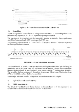
11.1 OTUk frame structure
The OTUk (k = 1,2,3,4) frame structure is based on the ODUk frame structure and extends it with a
forward error correction (FEC) as shown in Figure 11-1. 256 columns are added to the ODUk frame
for the FEC and the reserved overhead bytes in row 1, columns 8 to 14 of the ODUk overhead are
used for an OTUk specific overhead, resulting in an octet-based block frame structure with four
rows and 4080 columns. The MSB in each octet is bit 1, the LSB is bit 8.
NOTE – This Recommendation does not specify an OTUk frame structure for k=0, k=2e or k=flex.
G.709-Y.1331(12)_F11-1
.......
.............. .......
1
1
2
3
4
3824
3825 408014 15
ODUk
OTUk FEC
FA OH OTUk OH
OTUk
(4 256 bytes)×
1
1
2
3
4
3824
Figure 11-1 − OTUk frame structure
The bit rates of the OTUk signals are defined in Table 7-1.
The OTUk (k=1,2,3,4) forward error correction (FEC) contains the Reed-Solomon RS(255,239)
FEC codes. Transmission of the OTUk FEC is mandatory for k=4 and optional for k=1,2,3. If no
FEC is transmitted, fixed stuff bytes (all-0s pattern) are to be used.
The RS(255,239) FEC code shall be computed as specified in Annex A.
For interworking of equipment supporting FEC, with equipment not supporting FEC (inserting
fixed stuff all-0s pattern in the OTUk (k=1,2,3) FEC area), the FEC supporting equipment shall
support the capability to disable the FEC decoding process (ignore the content of the OTUk
(k=1,2,3) FEC).
The transmission order of the bits in the OTUk frame is left to right, top to bottom, and MSB to
LSB (see Figure 11-2).](https://image.slidesharecdn.com/dd175b1f-a76f-4140-ae81-1f3e866587da-160607171351/85/T-REC-G-709-201202-I-PDF-E-46-320.jpg)
![Rec. ITU-T G.709/Y.1331 (02/2012) 45
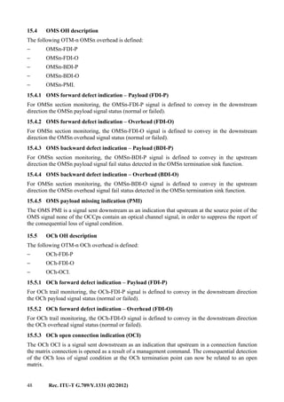
15.1.3 Optical channel transport unit overhead (OTUk OH)
OTUk OH information is part of the OTUk signal structure. It includes information for operational
functions to support the transport via one or more optical channel connections. The OTUk OH is
terminated where the OTUk signal is assembled and disassembled. The specific OH format and
coding is defined in clauses 15.6 and 15.7.
The specific frame structure and coding for the non-standard OTUkV OH is outside the scope of
this Recommendation. Only the required basic functionality that has to be supported is defined
in clause 15.7.3.
15.1.4 Optical channel non-associated overhead (OCh OH)
OCh OH information is added to the OTUk to create an OCh. It includes information for
maintenance functions to support fault management. The OCh OH is terminated where the OCh
signal is assembled and disassembled.
The specific frame structure and coding for the OCh OH is outside the scope of this
Recommendation. Only the required basic functionality that has to be supported is defined in
clause 15.5.
15.1.5 Optical multiplex section overhead (OMS OH)
OMS OH information is added to the OCG to create an OMU. It includes information for
maintenance and operational functions to support optical multiplex sections. The OMS OH is
terminated where the OMU is assembled and disassembled.
The specific frame structure and coding for the OMS OH is outside the scope of this
Recommendation. Only the required basic functionality that has to be supported is defined in
clause 15.4.
15.1.6 Optical transmission section overhead (OTS OH)
OTS OH information is added to the information payload to create an OTM. It includes information
for maintenance and operational functions to support optical transmission sections. The OTS OH is
terminated where the OTM is assembled and disassembled.
The specific frame structure and coding for the OTS OH is outside the scope of this
Recommendation. Only the required basic functionality that has to be supported is defined in
clause 15.3.
15.1.7 General management communications overhead (COMMS OH)
COMMS OH information is added to the information payload to create an OTM. It provides general
management communication between network elements. The specific frame structure and coding
for the COMMS OH is outside the scope of this Recommendation.
15.2 Trail trace identifier and access point identifier definition
A trail trace identifier (TTI) is defined as a 64-byte string with the following structure
(see Figure 15-4):
− TTI[0] contains the SAPI[0] character, which is fixed to all-0s.
− TTI[1] to TTI[15] contain the 15-character source access point identifier (SAPI[1] to
SAPI[15]).
− TTI[16] contains the DAPI[0] character, which is fixed to all-0s.
− TTI[17] to TTI[31] contain the 15-character destination access point identifier (DAPI[1] to
DAPI[15]).
− TTI[32] to TTI[63] are operator specific.](https://image.slidesharecdn.com/dd175b1f-a76f-4140-ae81-1f3e866587da-160607171351/85/T-REC-G-709-201202-I-PDF-E-53-320.jpg)
![46 Rec. ITU-T G.709/Y.1331 (02/2012)
.............
......
......
......
......
......
......
G.709-Y.1331(12)_F15-4
Source
access
point
identifier
Destination
access
point
identifier
Operator
specific
SAPI[0]
1 2 3 4 5 6 7 8
SAPI[1]
SAPI[2]
SAPI[15]
0
0
0
1
2
15
0
DAPI[0]
DAPI[1]
DAPI[2]
DAPI[15]
0
0
0
17
18
31
16
32
63
Figure 15-4 − TTI structure
The features of access point identifiers (APIs) are:
– Each access point identifier must be globally unique in its layer network.
– Where it may be expected that the access point may be required for path set-up across an
inter-operator boundary, the access point identifier must be available to other network
operators.
– The access point identifier should not change while the access point remains in existence.
– The access point identifier should be able to identify the country and network operator
which is responsible for routing to and from the access point.
– The set of all access point identifiers belonging to a single administrative layer network
should form a single access point identification scheme.
– The scheme of access point identifiers for each administrative layer network can be
independent from the scheme in any other administrative layer network.
It is recommended that the ODUk, OTUk and OTM should each have the access point identification
scheme based on a tree-like format to aid routing control search algorithms. The access point
identifier should be globally unambiguous.
The access point identifier (SAPI, DAPI) shall consist of a three-character international segment
and a twelve-character national segment (NS) (see Figure 15-5). These characters shall be coded
according to [ITU-T T.50] (International Reference Alphabet – 7-bit coded character set for
information exchange).](https://image.slidesharecdn.com/dd175b1f-a76f-4140-ae81-1f3e866587da-160607171351/85/T-REC-G-709-201202-I-PDF-E-54-320.jpg)
![Rec. ITU-T G.709/Y.1331 (02/2012) 47
IS character # NS character #
1 2 3 4 5 6 7 8 9 10 11 12 13 14 15
CC ICC UAPC
CC ICC UAPC
CC ICC UAPC
CC ICC UAPC
CC ICC UAPC
CC ICC UAPC
Figure 15-5 − Access point identifier structure
The international segment field provides a three-character ISO 3166 geographic/political country
code (G/PCC). The country code shall be based on the three-character uppercase alphabetic
ISO 3166 country code (e.g., USA, FRA).
The national segment field consists of two subfields: the ITU carrier code (ICC) followed by a
unique access point code (UAPC).
The ITU carrier code is a code assigned to a network operator/service provider, maintained by the
ITU-T Telecommunication Standardization Bureau (TSB) as per [ITU-T M.1400]. This code shall
consist of 1-6 left-justified characters, alphabetic, or leading alphabetic with trailing numeric.
The unique access point code shall be a matter for the organization to which the country code and
ITU carrier code have been assigned, provided that uniqueness is guaranteed. This code shall
consist of 6-11 characters, with trailing NUL, completing the 12-character national segment.
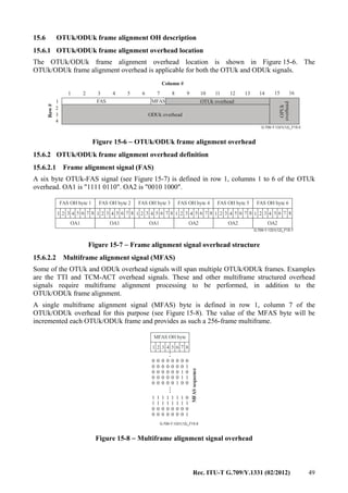
15.3 OTS OH description
The following OTM-n OTSn overhead is defined:
− OTSn-TTI
− OTSn-BDI-P
− OTSn-BDI-O
− OTSn-PMI.
15.3.1 OTS trail trace identifier (TTI)
The OTSn-TTI is defined to transport a 64-byte TTI as specified in clause 15.2 for OTSn section
monitoring.
15.3.2 OTS backward defect indication – Payload (BDI-P)
For OTSn section monitoring, the OTSn-BDI-P signal is defined to convey in the upstream
direction the OTSn payload signal fail status detected in the OTSn termination sink function.
15.3.3 OTS backward defect indication – Overhead (BDI-O)
For OTSn section monitoring, the OTSn-BDI-O signal is defined to convey in the upstream
direction the OTSn overhead signal fail status detected in the OTSn termination sink function.
15.3.4 OTS payload missing indication (PMI)
The OTS PMI is a signal sent downstream as an indication that upstream at the source point of the
OTS signal no payload is added, in order to suppress the report of the consequential loss of signal
condition.](https://image.slidesharecdn.com/dd175b1f-a76f-4140-ae81-1f3e866587da-160607171351/85/T-REC-G-709-201202-I-PDF-E-55-320.jpg)
![Rec. ITU-T G.709/Y.1331 (02/2012) 51
15.7.2.1.1 OTUk SM trail trace identifier (TTI)
For section monitoring, a one-byte trail trace identifier (TTI) overhead is defined to transport the
64-byte TTI signal specified in clause 15.2 or a discovery message as specified in
[ITU-T G.7714.1].
The 64-byte TTI signal shall be aligned with the OTUk multiframe (see clause 15.6.2.2) and
transmitted four times per multiframe. Byte 0 of the 64-byte TTI signal shall be present at OTUk
multiframe positions 0000 0000 (0x00), 0100 0000 (0x40), 1000 0000 (0x80) and 1100 0000
(0xC0).
15.7.2.1.2 OTUk SM error detection code (BIP-8)
For section monitoring, a one-byte error detection code signal is defined. This byte provides a bit
interleaved parity-8 (BIP-8) code.
NOTE – The notation BIP-8 refers only to the number of BIP bits and not to the EDC usage (i.e., what
quantities are counted). For definition of BIP-8 refer to BIP-X definition in [ITU-T G.707].
The OTUk BIP-8 is computed over the bits in the OPUk (columns 15 to 3824) area of
OTUk frame i, and inserted in the OTUk BIP-8 overhead location in OTUk frame i+2
(see Figure 15-11).
..............
G.709-Y.1331(12)_F15-11
1 14 15 3824
BIP8
BIP8
OPUk
BIP8BIP8
FrameiFramei+1Framei+2
1
2
3
4
1
2
3
4
1
2
3
4
Figure 15-11 − OTUk SM BIP-8 computation
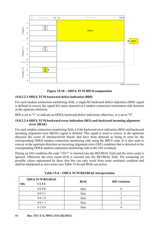
15.7.2.1.3 OTUk SM backward defect indication (BDI)
For section monitoring, a single-bit backward defect indication (BDI) signal is defined to convey
the signal fail status detected in a section termination sink function in the upstream direction.
BDI is set to "1" to indicate an OTUk backward defect indication; otherwise, it is set to "0".
15.7.2.1.4 OTUk SM backward error indication and backward incoming alignment error
(BEI/BIAE)
For section monitoring, a four-bit backward error indication (BEI) and backward incoming
alignment error (BIAE) signal is defined. This signal is used to convey in the upstream direction the
count of interleaved-bit blocks that have been detected in error by the corresponding OTUk section](https://image.slidesharecdn.com/dd175b1f-a76f-4140-ae81-1f3e866587da-160607171351/85/T-REC-G-709-201202-I-PDF-E-59-320.jpg)
![52 Rec. ITU-T G.709/Y.1331 (02/2012)
monitoring sink using the BIP-8 code. It is also used to convey in the upstream direction an
incoming alignment error (IAE) condition that is detected in the corresponding OTUk section
monitoring sink in the IAE overhead.
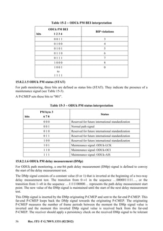
During an IAE condition the code "1011" is inserted into the BEI/BIAE field and the error count is
ignored. Otherwise the error count (0-8) is inserted into the BEI/BIAE field. The remaining six
possible values represented by these four bits can only result from some unrelated condition and
shall be interpreted as zero errors (see Table 15-1) and BIAE not active.
Table 15-1 − OTUk SM BEI/BIAE interpretation
OTUk SM BEI/BIAE
bits 1 2 3 4
BIAE BIP violations
0 0 0 0 false 0
0 0 0 1 false 1
0 0 1 0 false 2
0 0 1 1 false 3
0 1 0 0 false 4
0 1 0 1 false 5
0 1 1 0 false 6
0 1 1 1 false 7
1 0 0 0 false 8
1 0 0 1, 1 0 1 0 false 0
1 0 1 1 true 0
1 1 0 0
to
1 1 1 1
false 0
15.7.2.1.5 OTUk SM incoming alignment error overhead (IAE)
A single-bit incoming alignment error (IAE) signal is defined to allow the S-CMEP ingress point to
inform its peer S-CMEP egress point that an alignment error in the incoming signal has been
detected.
IAE is set to "1" to indicate a frame alignment error, otherwise it is set to "0".
The S-CMEP egress point may use this information to suppress the counting of bit errors, which
may occur as a result of a frame phase change of the OTUk at the ingress of the section.
15.7.2.1.6 OTUk SM reserved overhead (RES)
For section monitoring, two bits are reserved (RES) for future international standardization. They
are set to "00".
15.7.2.2 OTUk general communication channel 0 (GCC0)
Two bytes are allocated in the OTUk overhead to support a general communications channel or a
discovery channel as specified in [ITU-T G.7714.1] between OTUk termination points.
This general communication channel is a clear channel and any format specification is outside of
the scope of this Recommendation. These bytes are located in row 1, columns 11 and 12 of the
OTUk overhead.](https://image.slidesharecdn.com/dd175b1f-a76f-4140-ae81-1f3e866587da-160607171351/85/T-REC-G-709-201202-I-PDF-E-60-320.jpg)
![54 Rec. ITU-T G.709/Y.1331 (02/2012)
............ Operator
specific
TTIi BIP-8i
BEIi/BIAEi
BDIi
STATi
1 2 3 4 5 6 7 8
1 2 3
TCMi
63
32
0
15
16
31
SAPI
DAPI
DMt1
DMt2
DMt3
DMt4
DMt5
DMt6
1 2 3 4 5 6 7 8
PM and TCM
G.709-Y.1331(12)_F15-14
Figure 15-14 − ODUk tandem connection monitoring #i overhead
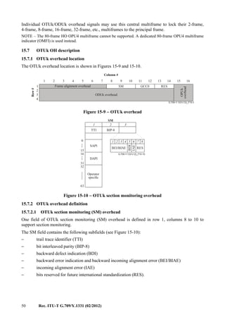
15.8.2 ODUk OH definition
15.8.2.1 ODUk path monitoring (PM) overhead
One field of an ODUk path monitoring overhead (PM) is defined in row 3, columns 10 to 12 to
support path monitoring and one additional bit of path monitoring is defined in row 2, column 3,
bit 7.
The PM field contains the following subfields (see Figure 15-13):
− trail trace identifier (TTI)
− bit interleaved parity (BIP-8)
− backward defect indication (BDI)
− backward error indication (BEI)
− status bits indicating the presence of a maintenance signal (STAT).
The PM&TCM field contains the following PM subfield (see Figure 15-13):
− path delay measurement (DMp).
The content of the PM field, except the STAT subfield, will be undefined (pattern will be all-1s,
0110 0110 or 0101 0101 repeating) during the presence of a maintenance signal (e.g., ODUk-AIS,
ODUk-OCI, ODUk-LCK). The content of the PM&TCM field will be undefined (pattern will be
all-1s, 0110 0110 or 0101 0101 repeating) during the presence of a maintenance signal. Refer to
clause 16.5.
15.8.2.1.1 ODUk PM trail trace identifier (TTI)
For path monitoring, a one-byte trail trace identifier (TTI) overhead is defined to transport the
64-byte TTI signal specified in clause 15.2 or a discovery message as specified in
[ITU-T G.7714.1].
The 64-byte TTI signal shall be aligned with the ODUk multiframe (see clause 15.6.2.2) and
transmitted four times per multiframe. Byte 0 of the 64-byte TTI signal shall be present at ODUk
multiframe positions 0000 0000 (0x00), 0100 0000 (0x40), 1000 0000 (0x80) and 1100 0000
(0xC0).](https://image.slidesharecdn.com/dd175b1f-a76f-4140-ae81-1f3e866587da-160607171351/85/T-REC-G-709-201202-I-PDF-E-62-320.jpg)
![Rec. ITU-T G.709/Y.1331 (02/2012) 55
15.8.2.1.2 ODUk PM error detection code (BIP-8)
For path monitoring, a one-byte error detection code signal is defined. This byte provides a bit
interleaved parity-8 (BIP-8) code.
NOTE − The notation BIP-8 refers only to the number of BIP bits and not to the EDC usage (i.e., what
quantities are counted). For definition of BIP-8, refer to the BIP-X definition in [ITU-T G.707].
Each ODUk BIP-8 is computed over the bits in the OPUk (columns 15 to 3824) area of ODUk
frame i, and inserted in the ODUk PM BIP-8 overhead location in the ODUk frame i+2
(see Figure 15-15).
..............
G.709-Y.1331(12)_F15-15
1 14 15 3824
BIP8
BIP8
OPUk
BIP8BIP8
FrameiFramei+1Framei+2
1
2
3
4
1
2
3
4
1
2
3
4
Figure 15-15 − ODUk PM BIP-8 computation
15.8.2.1.3 ODUk PM backward defect indication (BDI)
For path monitoring, a single-bit backward defect indication (BDI) signal is defined to convey the
signal fail status detected in a path termination sink function in the upstream direction.
BDI is set to "1" to indicate an ODUk backward defect indication, otherwise it is set to "0".
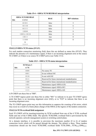
15.8.2.1.4 ODUk PM backward error indication (BEI)
For path monitoring, a four-bit backward error indication (BEI) signal is defined to convey in the
upstream direction the count of interleaved-bit blocks that have been detected in error by the
corresponding ODUk path monitoring sink using the BIP-8 code. This count has nine legal values,
namely 0-8 errors. The remaining seven possible values represented by these four bits can only
result from some unrelated condition and shall be interpreted as zero errors (see Table 15-2).
Table 15-2 − ODUk PM BEI interpretation
ODUk PM BEI
bits 1 2 3 4
BIP violations
0 0 0 0 0
0 0 0 1 1
0 0 1 0 2](https://image.slidesharecdn.com/dd175b1f-a76f-4140-ae81-1f3e866587da-160607171351/85/T-REC-G-709-201202-I-PDF-E-63-320.jpg)
![Rec. ITU-T G.709/Y.1331 (02/2012) 57
for bit errors emulating the start of delay measurement indication. The additional frames that are
used for such persistency checking should not be added to the delay frame count. The looping
P-CMEP should loop back each received DMp bit within approximately 100 µs.
Refer to [ITU-T G.798] for the specific path delay measurement process specifications.
NOTE 1 – Path delay measurements can be performed on-demand, to provide the momentary two-way
transfer delay status, and pro-active, to provide 15-minute and 24-hour two-way transfer delay performance
management snapshots.
NOTE 2 – Equipment designed according to the 2008 or earlier versions of this Recommendation may not be
capable of supporting this path delay monitoring. For such equipment, the DMp bit is a bit reserved for
future international standardization and set to zero.
NOTE 3 – This process measures a round trip delay. The one way delay may not be half of the round trip
delay in the case where the transmit and receive directions of the ODUk path are of unequal lengths (e.g., in
networks deploying unidirectional protection switching).
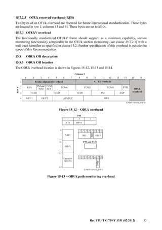
15.8.2.2 ODUk tandem connection monitoring (TCM) overhead
Six fields of an ODUk tandem connection monitoring (TCM) overhead are defined in row 2,
columns 5 to 13 and row 3, columns 1 to 9 of the ODUk overhead; and six additional bits of tandem
connection monitoring are defined in row 2, column 3, bits 1 to 6. TCM supports monitoring of
ODUk connections for one or more of the following network applications (refer to [ITU-T G.805],
[ITU-T G.872], [ITU-T G.873.2] and [ITU-T G.7714.1]):
− optical UNI-to-UNI tandem connection monitoring; monitoring the ODUk connection
through the public transport network (from public network ingress network termination to
egress network termination);
− optical NNI-to-NNI tandem connection monitoring; monitoring the ODUk connection
through the network of a network operator (from operator network ingress network
termination to egress network termination);
− sublayer monitoring for linear 1+1, 1:1 and 1:n optical channel subnetwork connection
protection switching, to determine the signal fail and signal degrade conditions;
− sublayer monitoring for optical channel data unit shared ring protection (SRP-1) protection
switching as specified in [ITU-T G.873.2], to determine the signal fail and signal degrade
conditions;
− sublayer monitoring for optical channel data unit connection passing through two or more
concatenated ODUk link connections (supported by back-to-back OTUk trails), to provide
a discovery message channel as specified in [ITU-T G.7714.1];
− monitoring an optical channel tandem connection for the purpose of detecting a signal fail
or signal degrade condition in a switched optical channel connection, to initiate automatic
restoration of the connection during fault and error conditions in the network;
− monitoring an optical channel tandem connection for, e.g., fault localization or verification
of delivered quality of service.
The six TCM fields are numbered TCM1, TCM2, ..., TCM6.
Each TCM field contains the following subfields (see Figure 15-14):
− trail trace identifier (TTI)
− bit interleaved parity 8 (BIP-8)
− backward defect indication (BDI)
− backward error indication and backward incoming alignment error (BEI/BIAE)
− status bits indicating the presence of a TCM overhead, incoming alignment error, or a
maintenance signal (STAT).](https://image.slidesharecdn.com/dd175b1f-a76f-4140-ae81-1f3e866587da-160607171351/85/T-REC-G-709-201202-I-PDF-E-65-320.jpg)
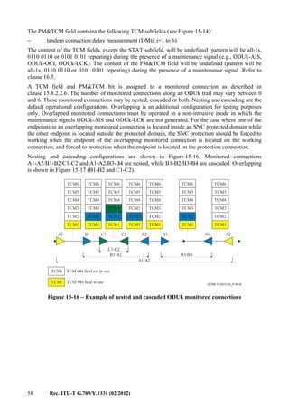
![Rec. ITU-T G.709/Y.1331 (02/2012) 59
G.709-Y.1331(12)_F15-17
TCM OH field not in use
TCM OH field in use
A1 B1 C1 B2 C2 A2
A1-A2
B1-B2
C1-C2
TCM1 TCM1
TCM2
TCM1 TCM1 TCM1
TCM2 TCM2 TCM2TCM2
TCM3
TCM4
TCM5
TCM6
TCMi
TCMi
TCM3
TCM4
TCM5
TCM6
TCM3 TCM3 TCM3
TCM4 TCM4 TCM4
TCM5 TCM5 TCM5
TCM6 TCM6 TCM6
Figure 15-17 − Example of overlapping ODUk monitored connections
15.8.2.2.1 ODUk TCM trail trace identifier (TTI)
For each tandem connection monitoring field, one byte of overhead is allocated for the transport of
the 64-byte trail trace identifier (TTI) specified in clause 15.2 or a discovery message as specified in
[ITU-T G.7714.1] for TCM6.
The 64-byte TTI signal shall be aligned with the ODUk multiframe (see clause 15.6.2.2) and
transmitted four times per multiframe. Byte 0 of the 64-byte TTI signal shall be present at ODUk
multiframe positions 0000 0000 (0x00), 0100 0000 (0x40), 1000 0000 (0x80) and 1100 0000
(0xC0).
15.8.2.2.2 ODUk TCM error detection code (BIP-8)
For each tandem connection monitoring field, a one-byte error detection code signal is defined. This
byte provides a bit interleaved parity-8 (BIP-8) code.
NOTE – The notation BIP-8 refers only to the number of BIP bits, and not to the EDC usage (i.e., what
quantities are counted). For definition of BIP-8 refer to the BIP-X definition in [ITU-T G.707].
Each ODUk TCM BIP-8 is computed over the bits in the OPUk (columns 15 to 3824) area of
ODUk frame i, and inserted in the ODUk TCM BIP-8 overhead location (associated with the
tandem connection monitoring level) in ODUk frame i+2 (see Figure 15-18).](https://image.slidesharecdn.com/dd175b1f-a76f-4140-ae81-1f3e866587da-160607171351/85/T-REC-G-709-201202-I-PDF-E-67-320.jpg)
![62 Rec. ITU-T G.709/Y.1331 (02/2012)
Overhead in TCM/DMt fields beyond the maximum (TCMmax+1/DMtmax+1 and above) may/will be
overwritten in the domain.
The TCM6 overhead field is assigned to monitor an ODUk connection which is supported by two or
more concatenated ODUk link connections (supported by back-to-back OTUk trails). [ITU-T
G.7714.1] specifies a discovery application which uses the TCM6 TTI SAPI field as discovery
message channel. [ITU-T G.873.2] specifies an ODU SRP-1 protection application which uses the
TCM6 field to monitor the status/performance of the ODU connection between two adjacent ODU
SRP-1 nodes.
Example
For the case of an ODUk leased circuit, the user may have been assigned one level of TCM, the
service provider one level of TCM and each network operator (having a contract with the service
provider) four levels of TCM. For the case where a network operator subcontracts part of its ODUk
connection to another network operator, these four levels are to be split; e.g., two levels for the
subcontracting operator.
This would result in the following TCM OH allocation:
– User: TCM1/DMt1 overhead field between the two user subnetworks, and
TCM1/DMt1..TCM6/DMt6 within its own subnetwork;
– Service provider (SP): TCM2/DMt2 overhead field between two UNIs;
– Network operators NO1, NO2, NO3 having contract with service provider: TCM3/DMt3,
TCM4/DMt4, TCM5/DMt5, TCM6/DMt6. Note that NO2 (which is subcontracting) cannot
use TCM5/DMt5 and TCM6/DMt6 in the connection through the domain of NO4;
– NO4 (having subcontract with NO2): TCM5/DMt5, TCM6/DMt6.
See Figure 15-19.
G.709-Y.1331(12)_F15-19
User UserNO1
NO2
NO3NO4
ODUk
path
ODUk
path
Service Provider
User
Network Operator 2
Network Operator 2
Network Operator 4
Network Operator 4
User
User
TCMoverheadfield
Network
Operator2
Network
Operator1
Network
O
perator2
Network
Operator3
TCM1
TCM2
TCM3
TCM4
TCM5
TCM6
Figure 15-19 – Example of TCM overhead field assignment
15.8.2.2.7 ODUk tandem connection monitoring activation/deactivation coordination protocol
A one-byte TCM activation/deactivation field is located in row 2, column 4. Its definition is for
further study.
15.8.2.2.8 ODUk TCM delay measurement (DMti, i=1 to 6)
For ODUk tandem connection monitoring, a one-bit tandem connection delay measurement (DMti)
signal is defined to convey the start of the delay measurement test.
The DMti signal consists of a constant value (0 or 1) that is inverted at the beginning of a two-way
delay measurement test. The transition from 0→1 in the sequence …0000011111…, or the](https://image.slidesharecdn.com/dd175b1f-a76f-4140-ae81-1f3e866587da-160607171351/85/T-REC-G-709-201202-I-PDF-E-70-320.jpg)
![Rec. ITU-T G.709/Y.1331 (02/2012) 63
transition from 1→0 in the sequence …1111100000… represents the path delay measurement start
point. The new value of the DMti signal is maintained until the start of the next delay measurement
test.
This DMti signal is inserted by the DMti originating TC-CMEP and sent to the far-end TC-CMEP.
This far-end TC-CMEP loops back the DMti signal towards the originating TC-CMEP. The
originating TC-CMEP measures the number of frame periods between the moment the DMti signal
value is inverted and the moment this inverted DMti signal value is received back from the far-end
TC-CMEP. The receiver should apply a persistency check on the received DMti signal to be
tolerant for bit errors emulating the start of delay measurement indication. The additional frames
that are used for such persistency checking should not be added to the delay frame count. The
looping TC-CMEP should loop back each received DMti bit within approximately 100 µs.
Refer to [ITU-T G.798] for the specific tandem connection delay measurement process
specifications.
NOTE 1 – Tandem connection delay measurements can be performed on-demand, to provide the momentary
two-way transfer delay status, and pro-active, to provide 15-minute and 24-hour two-way transfer delay
performance management snapshots.
NOTE 2 – Equipment designed according to the 2008 or earlier versions of this Recommendation may not be
capable of supporting this tandem connection delay monitoring. For such equipment, the DMti bit is a bit
reserved for future international standardization.
NOTE 3 – This process measures a round trip delay. The one way delay may not be half of the round trip
delay in the case where the transmit and receive directions of the ODUk tandem connection are of unequal
lengths (e.g., in networks deploying unidirectional protection switching).
15.8.2.3 ODUk general communication channels (GCC1, GCC2)
Two fields of two bytes are allocated in the ODUk overhead to support two general
communications channels or two discovery channels as specified in [ITU-T G.7714.1] between any
two network elements with access to the ODUk frame structure (i.e., at 3R regeneration points).
These general communication channels are clear channels and any format specification is outside of
the scope of this Recommendation. The bytes for GCC1 are located in row 4, columns 1 and 2, and
the bytes for GCC2 are located in row 4, columns 3 and 4 of the ODUk overhead.
15.8.2.4 ODUk automatic protection switching and protection communication channel
(APS/PCC)
A four-byte ODUk-APS/PCC signal is defined in row 4, columns 5 to 8 of the ODUk overhead. Up
to eight levels of nested APS/PCC signals may be present in this field. The APS/PCC bytes in a
given frame are assigned to a dedicated connection monitoring level depending on the value of
MFAS as follows:
Table 15-6 − Multiframe to allow separate APS/PCC for each monitoring level
MFAS
bits 6 7 8
APS/PCC channel applies to
connection monitoring level
Protection scheme using the
APS/PCC channel (Note 1)
0 0 0 ODUk Path ODUk SNC/Ne, ODUj CL-SNCG/I, Client
SNC/I, ODU SRP-p
0 0 1 ODUk TCM1 ODUk SNC/S, ODUk SNC/Ns
0 1 0 ODUk TCM2 ODUk SNC/S, ODUk SNC/Ns
0 1 1 ODUk TCM3 ODUk SNC/S, ODUk SNC/Ns
1 0 0 ODUk TCM4 ODUk SNC/S, ODUk SNC/Ns
1 0 1 ODUk TCM5 ODUk SNC/S, ODUk SNC/Ns](https://image.slidesharecdn.com/dd175b1f-a76f-4140-ae81-1f3e866587da-160607171351/85/T-REC-G-709-201202-I-PDF-E-71-320.jpg)
![64 Rec. ITU-T G.709/Y.1331 (02/2012)
Table 15-6 − Multiframe to allow separate APS/PCC for each monitoring level
1 1 0 ODUk TCM6 ODUk SNC/S, ODUk SNC/Ns, ODU SRP-1
1 1 1 ODUk server layer trail (Note 2) ODUk SNC/I
NOTE 1 – An APS channel may be used by more than one protection scheme and/or protection scheme
instance. In case of nested protection schemes, care should be taken when an ODUk protection is to be set
up in order not to interfere with the APS channel usage of another ODUk protection on the same
connection monitoring level, e.g., protection can only be activated if that APS channel of the level is not
already being used.
NOTE 2 – Examples of ODUk server layer trails are an OTUk or an HO ODUk (e.g., an ODU3
transporting an ODU1).
For linear protection schemes, the bit assignments for these bytes and the bit-oriented protocol are
given in [ITU-T G.873.1]. Bit assignment and byte-oriented protocol for ring protection schemes
are given in [ITU-T G.873.2].
15.8.2.5 ODUk fault type and fault location reporting communication channel (FTFL)
One byte is allocated in the ODUk overhead to transport a 256-byte fault type and fault location
(FTFL) message. The byte is located in row 2, column 14 of the ODUk overhead.
The 256-byte FTFL message shall be aligned with the ODUk multiframe (i.e., byte 0 of the
256-byte FTFL message shall be present at ODUk multiframe position 0000 0000, byte 1 of the
256-byte FTFL message shall be present at ODUk multiframe position 0000 0001, byte 2 of the
256-byte FTFL message shall be present at ODUk multiframe position 0000 0010, etc.).
The 256-byte FTFL message consists of two 128-byte fields as shown in Figure 15-20: the forward
and backward fields. The forward field is allocated to bytes 0 to 127 of the FTFL message. The
backward field is allocated to bytes 128 to 255 of the FTFL message.
G.709-Y.1331(12)_F15-20
Forward field Backward field
0 1 127 128 129 255
Figure 15-20 − FTFL message structure
The forward and backward fields are further divided into three subfields as shown in Figure 15-21:
the forward/backward fault type indication field, the forward/backward operator identifier field, and
the forward/backward operator-specific field.](https://image.slidesharecdn.com/dd175b1f-a76f-4140-ae81-1f3e866587da-160607171351/85/T-REC-G-709-201202-I-PDF-E-72-320.jpg)
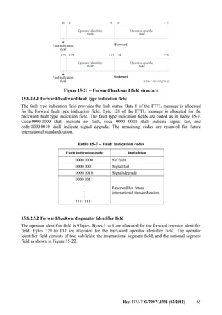
![66 Rec. ITU-T G.709/Y.1331 (02/2012)
G.709-Y.1331(12)_F15-22
Country code National segment code
NUL padding
NUL padding
NUL padding
NUL padding
Byte allocation in
backward field
Byte allocation in
forward field
NUL
NUL
padding
129 130 131 132 133 134 135 136 137
1 2 3 4 5 6 7 8 9
G/PCC ICC
G/PCC ICC
G/PCC ICC
G/PCC ICC
G/PCC ICC
G/PCC ICC
Figure 15-22 − Operator identifier field structure
The international segment field provides a three-character ISO 3166 geographic/political country
code (G/PCC). The first three bytes of the 9-byte operator identifier field (i.e., bytes 1 to 3 for the
forward operator identifier field and bytes 129 to 131 for the backward operator identifier field) are
reserved for the international segment field. The country code shall be based on the three-character
uppercase alphabetic ISO 3166 country code (e.g., USA, FRA).
The national segment field provides a 1-6 character ITU carrier code (ICC). The ICC is maintained
by the ITU-T Telecommunication Standardization Bureau (TSB) as per [ITU-T M.1400]. The
national segment field is 6 bytes and provides a 1-6 character ITU carrier code (ICC) with trailing
null characters to complete the 6-character field.
15.8.2.5.3 Forward/backward operator-specific field
Bytes 10 to 127 are allocated for the forward operator-specific field as shown in Figure 15-21.
Bytes 138 to 255 are allocated for the backward operator-specific field. The operator-specific fields
are not subject to standardization.
15.8.2.6 ODUk experimental overhead (EXP)
Two bytes are allocated in the ODUk overhead for experimental use. These bytes are located in
row 3, columns 13 and 14 of the ODUk overhead.
The use of these bytes is not subject to standardization and outside the scope of this
Recommendation.
An experimental overhead is provided in the ODUk OH to allow a vendor and/or a network
operator within their own (sub)network to support an application, which requires an additional
ODUk overhead.
There is no requirement to forward the EXP overhead beyond the (sub)network; i.e., the operational
span of the EXP overhead is limited to the (sub)network with the vendor's equipment, or the
network of the operator.
15.8.2.7 ODUk reserved overhead (RES)
Eight bytes and one bit are reserved in the ODUk overhead for future international standardization.
These bytes are located in row 2, columns 1 to 2 and row 4, columns 9 to 14 of the ODUk overhead.
The bit is located in row 2, column 3, bit 8 of the ODUk overhead. These bytes and bit are set to
all-0s.](https://image.slidesharecdn.com/dd175b1f-a76f-4140-ae81-1f3e866587da-160607171351/85/T-REC-G-709-201202-I-PDF-E-74-320.jpg)
![Rec. ITU-T G.709/Y.1331 (02/2012) 67
15.9 OPUk OH description
15.9.1 OPUk OH location
The OPUk overhead consists of: payload structure identifier (PSI) including the payload type (PT),
the overhead associated with concatenation and the overhead (e.g., justification control and
opportunity bits) associated with the mapping of client signals into the OPUk payload. The OPUk
PSI and PT overhead locations are shown in Figure 15-23.
G.709-Y.1331(12)_F15-23
.........
PSI
0
255
Mapping
and
concatenation
specific
PT
1
1 2 3 4 5 6 7 8 9 10 11 12 13 14 15 16
1
2
3
4
Row#
ODUk overhead
Column #
Frame alignment overhead OTUk overhead Mapping
and
concatenation
specific
Figure 15-23 − OPUk overhead
15.9.2 OPUk OH definition
15.9.2.1 OPUk payload structure identifier (PSI)
One byte is allocated in the OPUk overhead to transport a 256-byte payload structure identifier
(PSI) signal. The byte is located in row 4, column 15 of the OPUk overhead.
The 256-byte PSI signal is aligned with the ODUk multiframe (i.e., PSI[0] is present at ODUk
multiframe position 0000 0000, PSI[1] at position 0000 0001, PSI[2] at position 0000 0010, etc.).
PSI[0] contains a one-byte payload type. PSI[1] to PSI[255] are mapping and concatenation
specific, except for PT 0x01 (experimental mapping) and PTs 80-0x8F (for proprietary use).
15.9.2.1.1 OPUk payload type (PT)
A one-byte payload type signal is defined in the PSI[0] byte of the payload structure identifier to
indicate the composition of the OPUk signal. The code points are defined in Table 15-8.](https://image.slidesharecdn.com/dd175b1f-a76f-4140-ae81-1f3e866587da-160607171351/85/T-REC-G-709-201202-I-PDF-E-75-320.jpg)
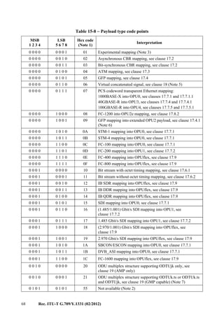
![Rec. ITU-T G.709/Y.1331 (02/2012) 69
Table 15-8 − Payload type code points
MSB
1 2 3 4
LSB
5 6 7 8
Hex code
(Note 1)
Interpretation
0 1 1 0 0 1 1 0 66 Not available (Note 2)
1 0 0 0 x x x x 80-8F Reserved codes for proprietary use (Note 4)
1 1 1 1 1 1 0 1 FD NULL test signal mapping, see clause 17.5.1
1 1 1 1 1 1 1 0 FE PRBS test signal mapping, see clause 17.5.2
1 1 1 1 1 1 1 1 FF Not available (Note 2)
NOTE 1 – There are 205 spare codes left for future international standardization. Refer to Annex A of
[ITU-T G.806] for the procedure to obtain one of these codes for a new payload type.
NOTE 2 – These values are excluded from the set of available code points. These bit patterns are present
in ODUk maintenance signals.
NOTE 3 – Value "01" is only to be used for experimental activities in cases where a mapping code is not
defined in this table. Refer to Annex A of [ITU-T G.806] for more information on the use of this code.
NOTE 4 – These 16 code values will not be subject to further standardization. Refer to Annex A of
[ITU-T G.806] for more information on the use of these codes.
Table 15-8 − Payload type code points
NOTE 5 – For the payload type of the virtual concatenated signal a dedicated payload type overhead
(vcPT) is used, see clause 18.
NOTE 6 – Supplement 43 (2008) to the ITU-T G-series of Recommendations indicated that this mapping
recommended using payload type 87.
NOTE 7 – Equipment supporting ODTUk.ts for OPU2 or OPU3 must be backward compatible with
equipment which supports only the ODTUjk. ODTUk.ts capable equipment transmitting PT=21 which
receives PT=20 from the far end shall revert to PT=20 and operate in ODTUjk only mode. Refer to
[ITU-T G.798] for the specification.
15.9.2.2 OPUk mapping specific overhead
Seven bytes are reserved in the OPUk overhead for the mapping and concatenation specific
overhead. These bytes are located in rows 1 to 3, columns 15 and 16 and column 16 row 4. In
addition, 255 bytes in the PSI are reserved for mapping and concatenation specific purposes.
The use of these bytes depends on the specific client signal mapping (defined in clauses 17 and 19),
the use of concatenation (see clause 18) and use of hitless adjustment of ODUflex(GFP) (see
[ITU-T G.7044]).
16 Maintenance signals
An alarm indication signal (AIS) is a signal sent downstream as an indication that an upstream
defect has been detected. An AIS signal is generated in an adaptation sink function. An AIS signal
is detected in a trail termination sink function to suppress defects or failures that would otherwise be
detected as a consequence of the interruption of the transport of the original signal at an upstream
point.
A forward defect indication (FDI) is a signal sent downstream as an indication that an upstream
defect has been detected. An FDI signal is generated in an adaptation sink function. An FDI signal
is detected in a trail termination sink function to suppress defects or failures that would otherwise be
detected as a consequence of the interruption of the transport of the original signal at an upstream
point.](https://image.slidesharecdn.com/dd175b1f-a76f-4140-ae81-1f3e866587da-160607171351/85/T-REC-G-709-201202-I-PDF-E-77-320.jpg)
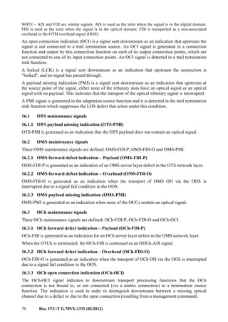
![Rec. ITU-T G.709/Y.1331 (02/2012) 71
NOTE – OCI is detected at the next downstream OTUk trail terminating equipment. If the connection was
opened intentionally, the related alarm report from this trail termination should be disabled by using the
alarm reporting control mode (refer to [ITU-T M.3100]).
16.4 OTUk maintenance signals
16.4.1 OTUk alarm indication signal (OTUk-AIS)
The OTUk-AIS (see Figure 16-1) is a generic-AIS signal (see clause 16.6.1). Since the OTUk
capacity (130 560 bits) is not an integer multiple of the PN-11 sequence length (2047 bits), the
PN-11 sequence may cross an OTUk frame boundary.
NOTE – OTUk-AIS is defined to support a future server layer application. OTN equipment should be
capable of detecting the presence of such a signal within OTM-0.1, OTM-0.2, OTM-0.3 interface signals and
within OChr interface signals (in an OTM-nr.m interface) carrying an OTU1, OTU2 or OTU3; it is not
required to generate such a signal.
.............. .......
G.709-Y.1331(12)_F16-1
Row#
Column #
3825 408014 151
1
2
3
4
3824
Repeating PN-11 sequence
Figure 16-1 − OTUk-AIS
16.5 ODUk maintenance signals
Three ODUk maintenance signals are defined: ODUk-AIS, ODUk-OCI and ODUk-LCK.
16.5.1 ODUk alarm indication signal (ODUk-AIS)
ODUk-AIS is specified as all "1"s in the entire ODUk signal, excluding the frame alignment
overhead (FA OH), OTUk overhead (OTUk OH) and ODUk FTFL (see Figure 16-2).
...............
Row#
G.709-Y.1331(12)_F16-2
1487 17
FA OH OTUk OH
1
1
2
3
4
3824
Column #
All-1s pattern
FTFL
STAT
STAT
STAT
STAT
STAT
STAT
STAT
Figure 16-2 − ODUk-AIS
In addition, the ODUk-AIS signal may be extended with one or more levels of ODUk tandem
connection, GCC1, GCC2, EXP and/or APS/PCC overhead before it is presented at the OTM
interface. This is dependent on the functionality between the ODUk-AIS insertion point and the
OTM interface.
The presence of the ODUk-AIS is detected by monitoring the ODUk STAT bits in the PM and
TCMi overhead fields.](https://image.slidesharecdn.com/dd175b1f-a76f-4140-ae81-1f3e866587da-160607171351/85/T-REC-G-709-201202-I-PDF-E-79-320.jpg)
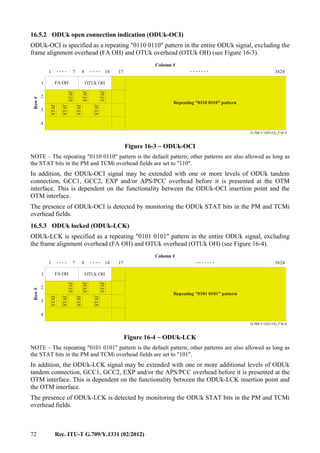
![Rec. ITU-T G.709/Y.1331 (02/2012) 73
16.6 Client maintenance signal
16.6.1 Generic AIS for constant bit rate signals
The generic-AIS signal is a signal with a 2 047-bit polynomial number 11 (PN-11) repeating
sequence.
The PN-11 sequence is defined by the generating polynomial 1 + x9
+ x11
as specified in clause 5.2
of [ITU-T O.150]. (See Figure 16-5.)
+
G.709-Y.1331(12)_F16-5
D D D D D D D D D D DQ Q Q Q Q Q Q Q Q Q Q
Clock
Generic-AIS
Figure 16-5 − Generic-AIS generating circuit
17 Mapping of client signals
This clause specifies the mapping of:
– STM-16, STM-64, STM-256 constant bit rate client signals into OPUk using client/server
specific asynchronous or bit-synchronous mapping procedures (AMP, BMP);
– 10GBASE-R constant bit rate client signal into OPU2e using client/server specific
bit-synchronous mapping procedure (BMP);
– FC-1200 constant bit rate client signal after timing transparent transcoding (TTT) providing
a 50/51 rate compression into OPU2e using client/server specific byte-synchronous
mapping procedure;
– constant bit rate client signals with bit rates up to 1.238 Gbit/s into OPU0 and up to
2.488 Gbit/s into OPU1 using a client agnostic generic mapping procedure (GMP) possibly
preceded by a timing transparent transcoding (TTT) of the client signal to reduce the bit
rate of the signal to fit the OPUk payload bandwidth;
– constant bit rate client signals into OPU1, OPU2, OPU3 or OPU4 respectively using a
client agnostic generic mapping procedure (GMP) possibly preceded by a timing
transparent transcoding (TTT) of the client signal to reduce the bit rate of the signal to fit
the OPUk payload bandwidth;
– other constant bit rate client signals into OPUflex using a client agnostic bit-synchronous
mapping procedure (BMP);
– asynchronous transfer mode (ATM);
– packet streams (e.g., Ethernet, MPLS, IP) which are encapsulated with the generic framing
procedure (GFP-F);
– test signals;
– continuous mode GPON constant bit rate client signal into OPU1 using asynchronous
mapping procedure (AMP);
– continuous mode XGPON constant bit rate client signal into OPU2 using asynchronous
mapping procedure (AMP);
into OPUk.](https://image.slidesharecdn.com/dd175b1f-a76f-4140-ae81-1f3e866587da-160607171351/85/T-REC-G-709-201202-I-PDF-E-81-320.jpg)
![74 Rec. ITU-T G.709/Y.1331 (02/2012)
17.1 OPUk client signal fail (CSF)
For support of local management systems, a single-bit OPUk client signal fail (CSF) indicator is
defined to convey the signal fail status of the CBR and Ethernet private line client signal mapped
into an LO OPUk at the ingress of the OTN to the egress of the OTN.
OPUk CSF is located in bit 1 of the PSI[2] byte of the payload structure identifier. Bits 2 to 8 of the
PSI[2] byte are reserved for future international standardization. These bits are set to all-0s.
OPUk CSF is set to "1" to indicate a client signal fail indication, otherwise it is set to "0".
NOTE – Equipment designed prior to this revision of the Recommendation will generate a "0" in the OPUk
CSF and will ignore any value in OPUk CSF.
17.2 Mapping of CBR2G5, CBR10G, CBR10G3 and CBR40G signals into OPUk
The mapping of a CBR2G5, CBR10G or CBR40G signal (with up to ±20 ppm bit-rate tolerance)
into an OPUk (k = 1,2,3) may be performed according to the bit-synchronous mapping procedure
based on one generic OPUk frame structure (see Figure 17-1). The mapping of a CBR2G5,
CBR10G or CBR40G signal (with up to ±45 ppm bit-rate tolerance) into an OPUk (k = 1,2,3) may
be performed according to the asynchronous mapping procedure. The mapping of a CBR10G3
signal (with up to ±100 ppm bit-rate tolerance) into an OPUk (k = 2e) is performed using the
bit-synchronous mapping procedure.
NOTE 1 – Examples of CBR2G5, CBR10G and CBR40G signals are STM-16 and CMGPON_D/U2 (refer
to [ITU-T G.984.6]), STM-64 and CMXGPON_D/U2 [ITU-T G.987.4] and STM-256. An example of a
CBR10G3 signal is 10GBASE-R.
NOTE 2 – The maximum bit-rate tolerance between an OPUk and the client signal clock, which can be
accommodated by the asynchronous mapping scheme, is ±65 ppm. With a bit-rate tolerance of ±20 ppm for
the OPUk clock, the client signal's bit-rate tolerance can be ±45 ppm.
NOTE 3 – For OPUk (k=1,2,3) the clock tolerance is ±20 ppm. For OPU2e the clock tolerance is ±100 ppm
and asynchronous mapping cannot be supported with this justification overhead.
...........
...
G.709-Y.1331(12)_F17-1
0
255
RES
PT
1
2
17
PJO
1816
JC
JC
JC
NJO
15
1
2
3
4
3824
Column
Row
RES
RES
RES
PSI
OPUk OH
OPUk payload (4 3808 bytes)×
CSF
0 1 2 3 4 5 6 7 8
Reserved JCJC
PSI
Figure 17-1 − OPUk frame structure for the mapping of a CBR2G5,
CBR10G or CBR40G signal
The OPUk overhead for these mappings consists of a payload structure identifier (PSI) including
the payload type (PT), a client signal fail (CSF) indicator and 254 bytes plus 7 bits reserved for
future international standardization (RES), three justification control (JC) bytes, one negative
justification opportunity (NJO) byte, and three bytes reserved for future international](https://image.slidesharecdn.com/dd175b1f-a76f-4140-ae81-1f3e866587da-160607171351/85/T-REC-G-709-201202-I-PDF-E-82-320.jpg)
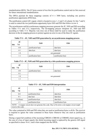
![76 Rec. ITU-T G.709/Y.1331 (02/2012)
During a signal fail condition of the incoming 10GBASE-R type CBR10G3 client signal (e.g., in
the case of a loss of input signal), this failed incoming 10GBASE-R signal is replaced by a stream
of 66B blocks, with each block carrying two local fault sequence ordered sets (as specified in
[IEEE 802.3]). This replacement signal is then mapped into the OPU2e.
During the signal fail condition of the incoming ODUk/OPUk signal (e.g., in the case of an
ODUk-AIS, ODUk-LCK, ODUk-OCI condition) the generic-AIS pattern as specified in
clause 16.6.1 is generated as a replacement signal for the lost CBR2G5, CBR10G or CBR40G
signal.
During the signal fail condition of the incoming ODU2e/OPU2e signal (e.g., in the case of an
ODU2e-AIS, ODU2e-LCK, ODU2e-OCI condition) a stream of 66B blocks, with each block
carrying two local fault sequence ordered sets (as specified in [IEEE 802.3]) is generated as a
replacement signal for the lost 10GBASE-R signal.
NOTE 4 – Local fault sequence ordered set is /K28.4/D0.0/D0.0/D1.0/. The 66B block contains the
following value SH=10 0x55 00 00 01 00 00 00 01.
NOTE 5 – Equipment developed prior to the 2008 version of this Recommendation may generate a different
10GBASE-R replacement signal (e.g., Generic-AIS) than the local fault sequence ordered set.
Asynchronous mapping
The OPUk signal for the asynchronous mapping is created from a locally generated clock (within
the limits specified in Table 7-3), which is independent of the CBR2G5, CBR10G or CBR40G
(i.e., 4(k–1)
× 2 488 320 kbit/s (k = 1,2,3)) client signal.
The CBR2G5, CBR10G, CBR40G (i.e., 4(k–1)
× 2 488 320 kbit/s (k = 1,2,3)) signal is mapped into
the OPUk using a positive/negative/zero (pnz) justification scheme.
Bit-synchronous mapping
The OPUk clock for bit-synchronous mapping is derived from the CBR2G5, CBR10G, CBR40G or
CBR10G3 client signal. During signal fail conditions of the incoming CBR2G5, CBR10G,
CBR40G or CBR10G3 signal (e.g., in the case of a loss of input signal), the OPUk payload signal
bit rate shall be within the limits specified in Table 7-3 and neither a frequency nor frame phase
discontinuity shall be introduced. The resynchronization on the incoming CBR2G5, CBR10G,
CBR40G or CBR10G3 signal shall be done without introducing a frequency or frame phase
discontinuity.
The CBR2G5, CBR10G, CBR40G or CBR10G3 signal is mapped into the OPUk without using the
justification capability within the OPUk frame: NJO contains a justification byte, PJO contains a
data byte, and the JC signal is fixed to 00.
17.2.1 Mapping a CBR2G5 signal (e.g., STM-16, CMGPON_D/CMGPON_U2) into OPU1
Groups of eight successive bits (not necessarily being a byte) of the CBR2G5 signal are mapped
into a data (D) byte of the OPU1 (see Figure 17-2). Once per OPU1 frame, it is possible to perform
either a positive or a negative justification action.
...........
G.709-Y.1331(12)_F17-2
17
PJO
D D D
D D
D D D
D D D3805D
3805D
3805D
3805D
1816
JC
JC
JC
NJO
15
1
2
3
4
3824
RES
RES
RES
PSI
Row#
Column #
Figure 17-2 − Mapping of a CBR2G5 signal into OPU1](https://image.slidesharecdn.com/dd175b1f-a76f-4140-ae81-1f3e866587da-160607171351/85/T-REC-G-709-201202-I-PDF-E-84-320.jpg)
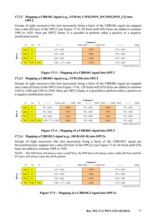
![78 Rec. ITU-T G.709/Y.1331 (02/2012)
17.3 Mapping of ATM cell stream into OPUk (k=0,1,2,3)
A constant bit rate ATM cell stream with a capacity that is identical to the OPUk (k=0,1,2,3)
payload area is created by multiplexing the ATM cells of a set of ATM VP signals. Rate adaptation
is performed as part of this cell stream creation process by either inserting idle cells or by
discarding cells. Refer to [ITU-T I.432.1]. The ATM cell stream is mapped into the OPUk payload
area with the ATM cell byte structure aligned to the ODUk payload byte structure
(see Figure 17-6). The ATM cell boundaries are thus aligned with the OPUk payload byte
boundaries. Since the OPUk payload capacity (15232 bytes) is not an integer multiple of the cell
length (53 bytes), a cell may cross an OPUk frame boundary.
...........
.......
G.709-Y.1331(12)_F17-6
..... .....
..... .....
0
255
RES
PT
1
171615
1
2
3
4
3824
RES RES
RES RES
RES RES
RESPSI
OPUk
overhead OPUk payload
ATM cell
53 bytes
PSI
Figure 17-6 − OPUk frame structure and mapping of ATM cells into OPUk
The ATM cell information field (48 bytes) shall be scrambled before mapping into the OPUk. In the
reverse operation, following termination of the OPUk signal, the ATM cell information field will be
descrambled before being passed to the ATM layer. A self-synchronizing scrambler with generator
polynomial x43 + 1 shall be used (as specified in [ITU-T I.432.1]). The scrambler operates for the
duration of the cell information field. During the 5-byte header the scrambler operation is
suspended and the scrambler state retained. The first cell transmitted on start-up will be corrupted
because the descrambler at the receiving end will not be synchronized to the transmitter scrambler.
Cell information field scrambling is required to provide security against false cell delineation and
the cell information field replicating the OTUk and ODUk frame alignment signal.
When extracting the ATM cell stream from the OPUk payload area after the ODUk termination, the
ATM cells must be recovered. The ATM cell header contains a header error control (HEC) field,
which may be used in a similar way to a frame alignment word to achieve cell delineation. This
HEC method uses the correlation between the header bits to be protected by the HEC (32 bits) and
the control bit of the HEC (8 bits) introduced in the header after computation with a shortened
cyclic code with generating polynomial g(x) = x8
+ x2
+ x + 1.
The remainder from this polynomial is then added to the fixed pattern "01010101" in order to
improve the cell delineation performance. This method is similar to conventional frame alignment
recovery where the alignment signal is not fixed but varies from cell to cell.
More information on HEC cell delineation is given in [ITU-T I.432.1].
The OPUk overhead for the ATM mapping consists of a payload structure identifier (PSI) including
the payload type (PT) and 255 bytes reserved for future international standardization (RES), and
seven bytes reserved for future international standardization (RES).
The OPUk payload for the ATM mapping consists of 4 × 3808 bytes.](https://image.slidesharecdn.com/dd175b1f-a76f-4140-ae81-1f3e866587da-160607171351/85/T-REC-G-709-201202-I-PDF-E-86-320.jpg)

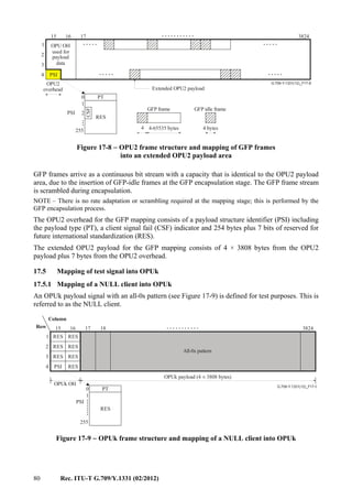
![Rec. ITU-T G.709/Y.1331 (02/2012) 81
The OPUk overhead for the NULL mapping consists of a payload structure identifier (PSI)
including the payload type (PT) and 255 bytes reserved for future international standardization
(RES), and seven bytes reserved for future international standardization (RES).
The OPUk payload for the NULL mapping consists of 4 × 3808 bytes.
17.5.2 Mapping of PRBS test signal into OPUk
For test purposes, a 2 147 483 647-bit pseudo-random test sequence (231
− 1) as specified in
clause 5.8 of [ITU-T O.150] can be mapped into the OPUk payload. Groups of eight successive bits
of the 2 147 483 647-bit pseudo-random test sequence signal are mapped into 8 data bits (8D)
(i.e., one byte) of the OPUk payload (see Figure 17-10).
...........
........
G.709-Y.1331(12)_F17-10
0
255
RES
PT
1
OPUk OH
OPUk payload (4 3808 bytes)×
PSI
17
8D 8D
8D 8D
8D 8D
8D 8D
8D
8D
8D
8D
3805 8D×
3805 8D×
3805 8D×
3805 8D×
181615
1
2
3
4
3824
RES RES
RES RES
RES RES
RESPSI
Figure 17-10 − OPUk frame structure and mapping of 2 147 483 647-bit
pseudo-random test sequence into OPUk
The OPUk overhead for the PRBS mapping consists of a payload structure identifier (PSI)
including the payload type (PT) and 255 bytes reserved for future international standardization
(RES), and seven bytes reserved for future international standardization (RES).
The OPUk payload for the PRBS mapping consists of 4 × 3808 bytes.
17.6 Mapping of a non-specific client bit stream into OPUk
In addition to the mappings of specific client signals as specified in the other subclauses of this
clause, a non-specific client mapping into OPUk is specified. Any (set of) client signal(s), which
after encapsulation into a continuous bit stream with a bit rate of the OPUk payload, can be mapped
into the OPUk payload (see Figure 17-11). The bit stream must be synchronous with the OPUk
signal. Any justification must be included in the continuous bit stream creation process. The
continuous bit stream must be scrambled before mapping into the OPUk payload.](https://image.slidesharecdn.com/dd175b1f-a76f-4140-ae81-1f3e866587da-160607171351/85/T-REC-G-709-201202-I-PDF-E-89-320.jpg)
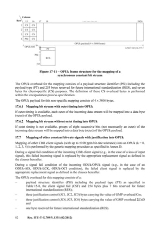
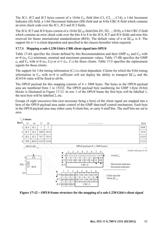
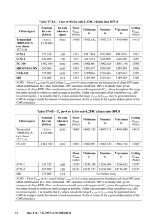
![Rec. ITU-T G.709/Y.1331 (02/2012) 85
Table 17-5 – Replacement signal for sub-1.238G clients
Client signal Replacement signal
Bit-rate tolerance
(ppm)
STM-1 Generic-AIS ±20
STM-4 Generic-AIS ±20
1000BASE-X Link Fault ±100
FC-100 NOS ±100
SBCON/ESCON NOS ±200
DVB-ASI Generic-AIS ±100
SDI Generic-AIS For further study
17.7.1.1 1000BASE-X transcoding
The 1000BASE-X signal (8B/10B coded, nominal bit rate of 1 250 000 kbit/s and a bit-rate
tolerance up to ±100 ppm) is synchronously mapped into a 75-octet GFP-T frame stream with a bit
rate of 15/16 × 1 250 000 kbit/s ±100 ppm (approximately 1 171 875 kbit/s ±100 ppm). This
process is referred to as "timing transparent transcoding (TTT)". The 15/16 × 1 250 000 kbit/s
±100 ppm signal is then mapped into an OPU0 by means of the generic mapping procedure as
specified in clause 17.7.1 and Annex D.
For 1000BASE-X client mapping, 1-bit timing information (C1) is not needed, so OPU0
JC4/JC5/JC6 OH value will be fixed to all-0s.
The mapping of the 1000BASE-X signal into GFP-T is performed as specified in [ITU-T G.7041]
with the following parameters:
– each GFP-T frame contains one superblock
– the 65B_PAD character is not used
– GFP idle frames are not used
– the GFP frame pFCS is not used.
During a signal fail condition of the incoming 1000BASE-X client signal (e.g., in the case of a loss
of input signal), either:
– this failed incoming 1000BASE-X signal is replaced by a stream of 10B blocks, with a bit
rate of 1 250 000 kbit/s ±100 ppm, each carrying a link fault indication as specified in
[IEEE 802.3], which stream is then applied at the GFP-T mapper, or
– the GFP-T signal is replaced by a stream of GFP client signal fail (CSF) and GFP-idle
frames as specified in [ITU-T G.7041] with a bit rate of 15/16 x 1 250 000 kbit/s
±100 ppm.
During either
– a signal fail condition of the incoming ODU0/OPU0 signal (e.g., in the case of an
ODU0-AIS, ODU0-LCK, ODU0-OCI condition), or
– incoming CSF frames as specified in [ITU-T G.7041]
the GFP-T de-mapper process generates a stream of 10B blocks, with each block carrying a link
fault indication as specified in [IEEE 802.3] as a replacement signal for the lost 1000BASE-X
signal.
NOTE – The Ethernet link fault indication is a stream of repeating /C1/C2/C1/C2/ … ordered sets, where
C1 = /K28.5/D21.5/D0.0/D0.0/ and C2 = /K28.5/D2.2/D0.0/D0.0/. This character stream is then processed](https://image.slidesharecdn.com/dd175b1f-a76f-4140-ae81-1f3e866587da-160607171351/85/T-REC-G-709-201202-I-PDF-E-93-320.jpg)
![86 Rec. ITU-T G.709/Y.1331 (02/2012)
by the GFP-T mapper process in the same manner as if it were the received 8B/10B data stream, mapping it
into GFP-T superblocks for transmission.
17.7.1.2 FC-100
During a signal fail condition of the incoming FC-100 signal (e.g., in the case of a loss of input
signal), this failed incoming FC-100 signal is replaced by an NOS primitive sequence as specified
in [b-INCITS 470].
NOTE – The NOS primitive sequence ordered set is defined as /K28.5/D21.2/D31.5/D5.2/.
During a signal fail condition of the incoming ODU0 signal (e.g., in the case of an ODU0-AIS,
ODU0-LCK, ODU0-OCI condition), NOS primitive sequence ordered sets as specified in
[b-INCITS 470] are generated as a replacement signal for the lost FC-100 signal.
17.7.1.3SBCON/ESCON
During a signal fail condition of the incoming SBCON/ESCON signal (e.g., in the case of a loss of
input signal), this failed incoming SBCON/ESCON signal is replaced by an NOS sequence as
specified in [b-ANSI INCITS 296].
NOTE – The NOS sequence ordered set is defined as /K28.5/D0.2/.
During a signal fail condition of the incoming ODU0 signal (e.g., in the case of an ODU0-AIS,
ODU0-LCK, ODU0-OCI condition), NOS sequence ordered sets as specified in [b-ANSI INCITS
296] are generated as a replacement signal for the lost SBCON/ESCON signal.
17.7.2 Mapping a supra-1.238 to sub-2.488 Gbit/s CBR client signal into OPU1
Table 17-6A specifies the clients defined by this Recommendation and their GMP cm and Cm with
m=16 (c16, C16) minimum, nominal and maximum parameter values. Table 17-6B specifies the
GMP cn and Cn with n=8 (c8, C8) or n=1 (c1, C1) for those clients. Table 17-7 specifies the
replacement signals for those clients.
The support for 8-bit timing information (ΣC8D) in the OPU1 JC4/JC5/JC6 OH is required.
The support for 1-bit timing information (ΣC1D) in the OPU1 JC4/JC5/JC6 OH is client dependent.
The OPU1 payload for this mapping consists of 4 × 3808 bytes. The groups of 2 bytes in the OPU1
payload area are numbered from 1 to 7616. The OPU1 payload byte numbering for GMP 2-byte
(16-bit) blocks is illustrated in Figure 17-13. In row 1 of the OPU1 frame the first 2-bytes will be
labelled 1, the next 2-bytes will be labelled 2, etc.
Groups of sixteen successive bits of the client signal are mapped into a group of 2 successive bytes
of the OPU1 payload area under control of the GMP data/stuff control mechanism. Each group of
2 bytes in the OPU1 payload area may either carry 16 client bits, or carry 16 stuff bits. The stuff bits
are set to zero.](https://image.slidesharecdn.com/dd175b1f-a76f-4140-ae81-1f3e866587da-160607171351/85/T-REC-G-709-201202-I-PDF-E-94-320.jpg)

![88 Rec. ITU-T G.709/Y.1331 (02/2012)
1.5G SDI 1 485 000 ±10 For further study
1.5G SDI 1 485 000/1.001 ±10 For further study
NOTE – Floor Cn,min (n=8,1) and Ceiling Cn,max (n=8,1) values represent the boundaries of client/OPU
ppm offset combinations (i.e., min. client/max. OPU and max. client/min. OPU). In steady state, given
instances of client/OPU offset combinations should not result in generated Cn values throughout this range
but rather should be within as small a range as possible. Under transient ppm offset conditions (e.g., AIS
to normal signal), it is possible that Cn values outside the range Cn, min to Cn, max may be generated and
a GMP de-mapper should be tolerant of such occurrences. Refer to Annex D for a general description of
the GMP principles.
Table 17-7 – Replacement signal for supra-1.238 to sub-2.488 Gbit/s clients
Client signal Replacement signal Bit-rate tolerance (ppm)
FC-200 NOS ±100
1.5G SDI Generic-AIS For further study
17.7.2.1 FC-200
During a signal fail condition of the incoming FC-200 signal (e.g., in the case of a loss of input
signal), this failed incoming FC-200 signal is replaced by an NOS primitive sequence as specified
in [b-INCITS 470].
NOTE – The NOS primitive sequence ordered set is defined as /K28.5/D21.2/D31.5/D5.2/.
During a signal fail condition of the incoming ODU1 signal (e.g., in the case of an ODU1-AIS,
ODU1-LCK, ODU1-OCI condition), NOS primitive sequence ordered sets as specified in
[b-INCITS 470] are generated as a replacement signal for the lost FC-200 signal.
17.7.3 Mapping CBR client signals into OPU2
Table 17-8A specifies the clients defined by this Recommendation and their GMP cm and Cm with
m=64 (c64, C64) minimum, nominal and maximum parameter values. Table 17-8B specifies the
GMP cn and Cn with n=8 (c8, C8) or n=1 (c1, C1) for those clients. Table 17-9 specifies the
replacement signals for those clients.
The support for 8-bit timing information (ΣC8D) in the OPU2 JC4/JC5/JC6 OH is required.
The support for 1-bit timing information (ΣC1D) in the OPU2 JC4/JC5/JC6 OH is client dependent.
The OPU2 payload for this mapping consists of 4 × 3808 bytes. The groups of eight bytes in the
OPU2 payload area are numbered from 1 to 1904. The OPU2 payload byte numbering for GMP
8-byte (64-bit) blocks is illustrated in Figure 17-14. In row 1 of the OPU2 frame the first 8-bytes
will be labelled 1, the next 8-bytes will be labelled 2, etc.
Groups of sixty-four successive bits of the client signal are mapped into a group of eight successive
bytes of the OPU2 payload area under control of the GMP data/stuff control mechanism. Each
group of eight bytes in the OPU2 payload area may either carry 64 client bits, or carry 64 stuff bits.
The stuff bits are set to zero.](https://image.slidesharecdn.com/dd175b1f-a76f-4140-ae81-1f3e866587da-160607171351/85/T-REC-G-709-201202-I-PDF-E-96-320.jpg)
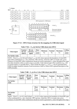
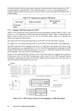
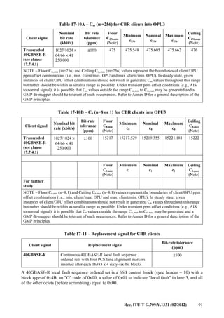
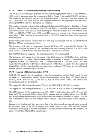
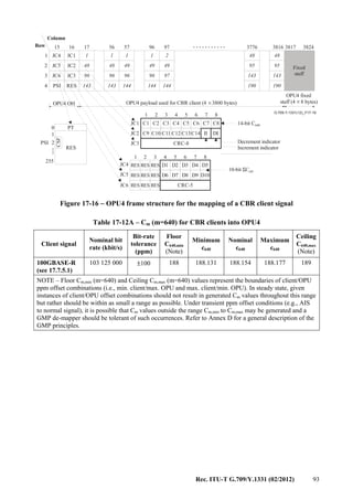
![94 Rec. ITU-T G.709/Y.1331 (02/2012)
Table 17-12B – Cn (n=8 or 1) for CBR clients into OPU4
Client signal
Nominal bit
rate (kbit/s)
Bit-rate
tolerance
(ppm)
Floor
C8,min
(Note)
Minimum
c8
Nominal
c8
Maximum
c8
Ceiling
C8,max
(Note)
100GBASE-R
(see 17.7.5.1)
103 125 000 ±100 15050 15050.518 15052.324 15054.131 15055
Floor
C1,min
(Note)
Minimum
c1
Nominal
c1
Maximum
c1
Ceiling
C1,max
(Note)
For further
study
NOTE – Floor Cn,min (n=8,1) and Ceiling Cn,max (n=8,1) values represent the boundaries of client/OPU ppm
offset combinations (i.e., min. client/max. OPU and max. client/min. OPU). In steady state, given
instances of client/OPU offset combinations should not result in generated Cn values throughout this range
but rather should be within as small a range as possible. Under transient ppm offset conditions (e.g., AIS
to normal signal), it is possible that Cn values outside the range Cn, min to Cn, max may be generated and a
GMP de-mapper should be tolerant of such occurrences. Refer to Annex D for a general description of the
GMP principles.
Table 17-13 – Replacement signal for CBR clients
Client signal Replacement signal Bit-rate tolerance (ppm)
100GBASE-R
(see 17.7.5.1)
Continuous 100GBASE-R local fault sequence
ordered sets with 20 PCS lane alignment markers
inserted after each 16383 x 20 sixty-six-bit blocks
±100
A 100GBASE-R local fault sequence ordered set is a 66B control block (sync header = 10) with a
block type of 0x4B, an "O" code of 0x00, a value of 0x01 to indicate a "local fault" in lane 3, and
all of the other octets (before scrambling) equal to 0x00.
17.7.5.1 100GBASE-R multi-lane processing
The 100GBASE-R client signal (64B/66B encoded, nominal aggregate bit-rate of
103 125 000 kbit/s ±100 ppm) is recovered using the process described in Annex E for parallel
64B/66B interfaces. The lane(s) of the physical interface are bit-disinterleaved, if necessary, into
twenty streams of 5 161 250 kbit/s. 66B block lock and lane alignment marker lock are acquired on
each PCS lane, allowing the 66B blocks to be de-skewed and reordered.
In the mapper, the received Ethernet PCS lane BIP may be compared with the expected Ethernet
PCS lane BIP as a non-intrusive monitor.
The de-mapper will pass through the PCS lane BIP from the ingress as described in Annex E. In
addition, the received Ethernet PCS lane BIP may be compared with the expected Ethernet PCS
lane BIP as a non-intrusive monitor.
For 100GBASE-R client mapping, 1-bit timing information (C1) is not needed.
The de-mapper will recover from the output of the GMP processor 64B/66B block lock per the state
diagram in Figure 82-10 [IEEE 802.3ba]. The 66B blocks are re-distributed round-robin to PCS
lanes. If the number of PCS lanes is greater than the number of physical lanes of the egress
interface, the appropriate numbers of PCS lanes are bit-multiplexed onto the physical lanes of the
egress interface.](https://image.slidesharecdn.com/dd175b1f-a76f-4140-ae81-1f3e866587da-160607171351/85/T-REC-G-709-201202-I-PDF-E-102-320.jpg)
![Rec. ITU-T G.709/Y.1331 (02/2012) 95
17.8 Mapping a 1000BASE-X and FC-1200 signal via timing transparent transcoding into
OPUk
17.8.1 Mapping a 1000BASE-X signal into OPU0
Refer to clause 17.7.1 for the mapping of the transcoded 1000BASE-X signal and to clause 17.7.1.1
for the transcoding of the 1000BASE-X signal.
17.8.2 Mapping an FC-1200 signal into OPU2e
The nominal line rate for FC-1200 is 10 518 750 kbit/s ± 100 ppm, and must therefore be
compressed to a suitable rate to fit into an OPU2e.
The adaptation of the 64B/66B encoded FC-1200 client is done by transcoding a group of eight
66B blocks into one 513B block (as described in Annex B), assembling eight 513B blocks into one
516-octet superblock and encapsulating seventeen 516-octet superblocks into an 8800 octet GFP
frame as illustrated in Figure 17-18. The GFP frame consists of 2200 rows with 32 bits per row. The
first row contains the GFP core header, the second row the GFP payload header. The next four rows
contain 16 bytes reserved for future international standardization. The next seventeen times
129 rows contain the seventeen superblocks #1 to #17. The last row contains the GFP payload FCS.
The flag (F) bit of 513B block #i (i = 0..7) is carried in Flag #i bit located in the superblock flags
field. The remaining 512 bits of each of the eight 513B blocks of a superblock are carried in
16 rows of the superblock data field; bits of 513B block #0 in the first 16 rows of the superblock,
bits of 513B block #1 in the next 16 rows, etc. Each 513B block contains 'j' (j = 0..8) control blocks
(CB1 to CBj) and '8-j' all-data blocks (DB1..DB8-j) as specified in Annex B. Figure 17-18 presents
a 513B block with three control blocks and five all-data blocks. A 513B block may contain zero to
eight control blocks and a superblock may contain thus zero to sixty-four control blocks.
NOTE 1 – The GFP encapsulation stage does not generate GFP-idle frames and therefore the generated GFP
stream is synchronous to the FC-1200 client stream. The adaptation process performs a 50/51 rate
compression, so the resulting GFP stream has a signal bit rate of 50/51 × 10.51875 Gbit/s ± 100 ppm (i.e.,
10 312 500 kbit/s ± 100 ppm).
The stream of 8800 octet GFP frames is byte-synchronous mapped into the OPU2e payload by
aligning the byte structure of every GFP frame with the byte structure of the OPU2e payload (see
Figure 17-17). Sixty-four fixed stuff (FS) bytes are added in columns 1905 to 1920 of the OPU2e
payload. All the GFP frames have the same length (8800 octets). The GFP frames are not aligned
with the OPU2e payload structure and may cross the boundary between two OPU2e frames.
During a signal fail condition of the incoming FC-1200 signal (e.g., in the case of a loss of input
signal), this failed incoming FC-1200 signal is replaced by a stream of 66B blocks, with each block
carrying two local fault sequence ordered sets as specified in [b-ANSI INCITS 364]. This
replacement signal is then applied at the transcoding process.
NOTE 2 – Local fault sequence ordered set is /K28.4/D0.0/D0.0/D1.0/. The 66B block contains the
following value SH=10 0x55 00 00 01 00 00 00 01.
During a signal fail condition of the incoming ODU2e/OPU2e signal (e.g., in the case of an
ODU2e-AIS, ODU2e-LCK, ODU2e-OCI condition) a stream of 66B blocks, with each block
carrying two local fault sequence ordered sets as specified in [b-ANSI INCITS 364] is generated as
a replacement signal for the lost FC-1200 signal.](https://image.slidesharecdn.com/dd175b1f-a76f-4140-ae81-1f3e866587da-160607171351/85/T-REC-G-709-201202-I-PDF-E-103-320.jpg)
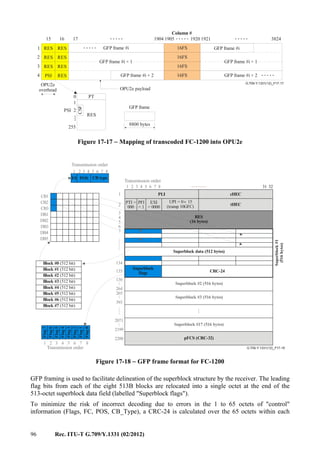
![Rec. ITU-T G.709/Y.1331 (02/2012) 97
superblock that may contain such "control" information and appended to form a 516 octet
superblock. The 65 octets in the 516-octet superblock over which the CRC-24 is calculated are the
octets (1+8n) with n=0..64 (i.e., octets 1, 9, 17, .., 513). The generator polynomial for the CRC-24 is
G(x) = x24
+ x21
+ x20
+ x17
+ x15
+ x11
+ x9
+ x8
+ x6
+ x5
+ x + 1 with an all-ones initialization value,
where x24
corresponds to the MSB and x0
to the LSB. This superblock CRC is generated by the
source adaptation process using the following steps:
1) The 65 octets of "control" information (Flags, POS, CB_Type) are taken in network octet
order (see Figure 17-18), most significant bit first, to form a 520-bit pattern representing the
coefficients of a polynomial M(x) of degree 519.
2) M(x) is multiplied by x24
and divided (modulo 2) by G(x), producing a remainder R(x) of
degree 23 or less.
3) The coefficients of R(x) are considered to be a 24-bit sequence, where x23
is the most
significant bit.
4) After inversion, this 24-bit sequence is the CRC-24.
Exactly 17 of these 516-octet superblocks are prefixed with the standard GFP core and type headers
and 16 octets of "reserved" (padding). Because the number of 516-octet superblocks per GFP frame
is known a priori, it is possible for this mapping scheme to operate in a cut-through (as opposed to
store and forward) fashion, thus minimizing the mapping latency.
The payload FCS (a CRC-32) is appended to the end of each GFP frame and is calculated across the
payload information field of the GFP frame as per [ITU-T G.7041]. The purpose of the payload
FCS is to provide visibility of bit errors occurring anywhere in the GFP payload information field
and thus augments the coverage provided by the per-superblock CRC-24 (which only provides
coverage for the "control" overhead in each superblock). The payload FCS is only for the purposes
of gathering statistics.
All octets in the GFP payload area are scrambled using the X43
+ 1 self-synchronous scrambler,
again as per [ITU-T G.7041].
17.9 Mapping a supra-2.488 CBR Gbit/s signal into OPUflex
Mapping of a supra-2.488 CBR Gbit/s client signal (with up to ±100 ppm bit-rate tolerance) into an
OPUflex is performed by a bit-synchronous mapping procedure (BMP). Table 17-14 specifies the
clients defined by this Recommendation.
The bit-synchronous mapping processes deployed to map constant bit rate client signals into an
OPUflex does not generate any justification control signals.
The OPUflex clock for the bit-synchronous mapping is derived from the client signal. During a
signal fail condition of the incoming client signal (e.g., in the case of a loss of input signal), this
failed incoming signal is replaced by the appropriate replacement signal as defined in Table 17-15.
The OPUflex payload signal bit rate shall be within the limits specified in Table 7-3 and neither a
frequency nor frame phase discontinuity shall be introduced. The resynchronization on the
incoming client signal shall be done without introducing a frequency or frame phase discontinuity.
During a signal fail condition of the incoming ODUflex/OPUflex signal (e.g., in the case of an
ODUflex-AIS, ODUflex-LCK, ODUflex-OCI condition), the failed client signal is replaced by the
appropriate replacement signal as defined in Table 17-15.
The OPUflex overhead for this mapping consists of:
– a payload structure identifier (PSI) including the payload type (PT) as specified in
Table 15-8, the client signal fail (CSF) and 254 bytes plus 7 bits reserved for future
international standardization (RES);](https://image.slidesharecdn.com/dd175b1f-a76f-4140-ae81-1f3e866587da-160607171351/85/T-REC-G-709-201202-I-PDF-E-105-320.jpg)
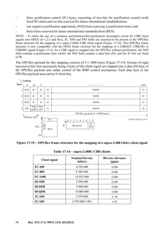
![Rec. ITU-T G.709/Y.1331 (02/2012) 99
Table 17-15 – Replacement signal for supra-2.488 Gbit/s clients
Client signal Replacement signal
Bit-rate tolerance
(ppm)
FC-400 NOS ±100
FC-800 NOS ±100
FC-1600 NOS ±100
IB SDR For further study ±100
IB DDR For further study ±100
IB QDR For further study ±100
3G SDI Generic-AIS For further study
17.9.1 FC-400 and FC-800
During a signal fail condition of the incoming FC-400/FC-800 signal (e.g., in the case of a loss of
input signal), this failed incoming FC-400/FC-800 signal is replaced by an NOS primitive sequence
as specified in [b-INCITS 470].
NOTE – The NOS primitive sequence ordered set is defined as /K28.5/D21.2/D31.5/D5.2/.
During a signal fail condition of the incoming ODUflex signal (e.g., in the case of an ODUflex-AIS,
ODUflex-LCK, ODUflex-OCI condition), NOS primitive sequence ordered sets as specified in
[b-INCITS 470] are generated as a replacement signal for the lost FC-400/FC-800 signal.
17.9.2 FC-1600
During a signal fail condition of the incoming FC-1600 signal (e.g., in the case of a loss of input
signal), this failed incoming FC-1600 signal is replaced by a NOS primitive sequence as specified
in [b-INCITS 470].
During signal fail condition of the incoming ODUflex signal (e.g., in the case of an ODUflex-AIS,
ODUflex-LCK, ODUflex-OCI condition), NOS primitive sequence ordered sets as specified in
[b-INCITS 470] are generated as a replacement signal for the lost FC-1600 signal.
18 Concatenation
Concatenation in the OTN is realized by means of virtual concatenation of OPUk signals.
18.1 Virtual concatenation of OPUk
18.1.1 Virtual concatenated OPUk (OPUk-Xv, k = 1 .. 3, X = 1 .. 256)
The OPUk-Xv (k = 1,2,3) frame structure is shown in Figure 18-1. It is organized in an octet-based
block frame structure with 4 rows and X × 3810 columns.
NOTE 1 – Virtual concatenation for OPUk with k=0,2e,4,flex is not supported.](https://image.slidesharecdn.com/dd175b1f-a76f-4140-ae81-1f3e866587da-160607171351/85/T-REC-G-709-201202-I-PDF-E-107-320.jpg)
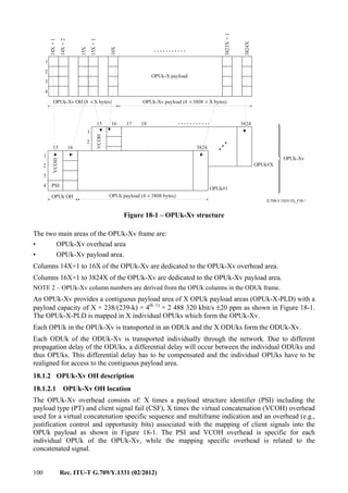
![Rec. ITU-T G.709/Y.1331 (02/2012) 101
The OPUk-Xv VCOH consists of a 3-byte VCOH per OPUk. The VCOH bytes in each OPUk are
used as defined in Figure 18-2.
.........
.........
.........
G.709-Y.1331(12)_F18-2
1
2
3
4
Column #
PSI
Row#
RES
255
254
0
1
2
PT
VCOH
1
VCOH
3
VCOH
2
1 1
1
9
0
8
12 2
2
23 3
3
34 4
4
45 5
5
56 6
6
67 7
7
78 8 8
CTRL
GID
RSA
CRC8
CRC8
CRC8
CRC8
CRC8
CRC8
CRC8
RES
255
0
1
2
Member status
(0-255)
VCOH1 VCOH2 VCOH3
MFI1
MFI2
SQ
Reserved
Reserved
Reserved
3
4
5
31
00000
00001
00010
00011
00100
00101
MFAS
45678
CRC8
vcPT
Mappingspecific
MSB LSB
RSA: RS-Ack
MSB LSB MSB LSB
11111
MFI1 MFI2SQ, CRC8 CTRL
1 12 23 34 45 56 67 78 81 2 3 4 5 6 7 8 1 2 3 4
CSF
Figure 18-2 – OPUk-Xv virtual concatenation overhead
18.1.2.2 OPUk-Xv OH definition
18.1.2.2.1 OPUk-Xv payload structure identifier (PSI)
In each OPUk of the OPUk-Xv one byte is allocated in row 4, column 15 (Figure 18-2) to transport
a 256-byte payload structure identifier (PSI) signal as defined in clause 15.9.2.
PSI[1]is used for a virtual concatenation specific payload type identifier (vcPT).
The PSI content is identical for each OPUk of the OPUk-Xv.
18.1.2.2.1.1 OPUk-Xv payload type (vcPT)
A one-byte OPUk-Xv payload type signal is defined in the PSI[1] byte of the payload structure
identifier to indicate the composition of the OPUk-Xv signal. The code points are defined in
Table 18-1.
Table 18-1 – Payload type (vcPT) code points for virtual
concatenated OPUk (OPUk-Xv) signals
MSB
1 2 3 4
LSB
5 6 7 8
Hex code
(Note 1)
Interpretation
0 0 0 0 0 0 0 1 01 Experimental mapping (Note 3)
0 0 0 0 0 0 1 0 02 Asynchronous CBR mapping, see clauses 18.2.1 and 18.2.2
0 0 0 0 0 0 1 1 03 Bit-synchronous CBR mapping, see clauses 18.2.1 and 18.2.2
0 0 0 0 0 1 0 0 04 ATM mapping, see clause 18.2.3](https://image.slidesharecdn.com/dd175b1f-a76f-4140-ae81-1f3e866587da-160607171351/85/T-REC-G-709-201202-I-PDF-E-109-320.jpg)
![102 Rec. ITU-T G.709/Y.1331 (02/2012)
Table 18-1 – Payload type (vcPT) code points for virtual
concatenated OPUk (OPUk-Xv) signals
MSB
1 2 3 4
LSB
5 6 7 8
Hex code
(Note 1)
Interpretation
0 0 0 0 0 1 0 1 05 GFP mapping, see clause 18.2.4
0 0 0 1 0 0 0 0 10 Bit stream with octet timing mapping, see clause 18.2.6
0 0 0 1 0 0 0 1 11 Bit stream without octet timing mapping, see clause 18.2.6
0 1 0 1 0 1 0 1 55 Not available (Note 2)
0 1 1 0 0 1 1 0 66 Not available (Note 2)
1 0 0 0 x x x x 80-8F Reserved codes for proprietary use (Note 4)
1 1 1 1 1 1 0 1 FD NULL test signal mapping, see clause 18.2.5.1
1 1 1 1 1 1 1 0 FE PRBS test signal mapping, see clause 18.2.5.2
1 1 1 1 1 1 1 1 FF Not available (Note 2)
NOTE 1 – There are 228 spare codes left for future international standardization. Refer to Annex A of
[ITU-T G.806] for the procedure to obtain one of these codes for a new payload type.
NOTE 2 – These values are excluded from the set of available code points. These bit patterns are present
in ODUk maintenance signals.
NOTE 3 – Value "01" is only to be used for experimental activities in cases where a mapping code is not
defined in the above table. Refer to Annex A of [ITU-T G.806] for more information on the use of this
code.
NOTE 4 – These 16 code values will not be subject to further standardization. Refer to Annex A of
[ITU-T G.806] for more information on the use of these codes.
18.1.2.2.1.2 OPUk-Xv payload structure identifier reserved overhead (RES)
253 bytes plus 7 bits are reserved in the OPUk PSI for future international standardization. These
bytes and bits are located in PSI[2] to PSI[255] of the OPUk overhead. These bytes are set to all-0s.
18.1.2.2.1.3 OPUk-Xv client signal fail (CSF)
For support of local management systems, a single-bit OPUk-Xv client signal fail (CSF) indicator is
defined to convey the signal fail status of the client signal mapped into an OPUk-Xv at the ingress
of the OTN to the egress of the OTN.
OPUk-Xv CSF is located in bit 1 of the PSI[2] byte of the payload structure identifier. Bits 2 to 8 of
the PSI[2] byte are reserved for future international standardization. These bits are set to all-0s.
OPUk-Xv CSF is set to "1" to indicate a client signal fail indication, otherwise it is set to "0".
NOTE – Equipment designed prior to this revision of the Recommendation will generate a "0" in the
OPUk-Xv CSF and will ignore any value in OPUk-Xv CSF.
18.1.2.2.2 OPUk-Xv virtual concatenation overhead (VCOH1/2/3)
Three bytes per individual OPUk of the OPUk-Xv are used to transport an 8 × 3 byte × 32 frame
structure for a virtual concatenation specific overhead. These bytes are located in rows 1, 2 and 3 of
column 15 as shown in Figure 18-2.
The structure is aligned with the ODUk multiframe and locked to bits 4, 5, 6, 7 and 8 of the MFAS.
The structure is repeated 8 times in the 256-frame multiframe.
The structure is used to transport multiframe sequences and the LCAS control overhead.](https://image.slidesharecdn.com/dd175b1f-a76f-4140-ae81-1f3e866587da-160607171351/85/T-REC-G-709-201202-I-PDF-E-110-320.jpg)
![Rec. ITU-T G.709/Y.1331 (02/2012) 103
18.1.2.2.2.1 OPUk-Xv virtual concatenation multiframe indicator (MFI1, MFI2)
A two-stage multiframe is introduced to cover a differential delay measurement (between the
member signals within the virtual concatenated group) and compensation (of those differential
delays) by the realignment process within the receiver.
The first stage uses MFAS in the frame alignment overhead area for the 8-bit multiframe indicator.
MFAS is incremented every ODUk frame and counts from 0 to 255.
The second stage uses the MFI1 and MFI2 overhead bytes in the VCOH. They form a 16-bit
multiframe counter with the MSBs in MFI1 and the LSBs in MFI2.
MFI1 is located in VCOH1[0] and MFI2 in VCOH1[1].
The multiframe counter of the second stage counts from 0 to 65535 and is incremented at the start
of each multiframe of the first stage (MFAS = 0).
The resulting overall multiframe (a combination of 1st multiframe and 2nd multiframe counter) is
16 777 216 ODUk frames long.
At the start of the OPUk-Xv the multiframe sequence of all individual OPUks of the OPUk-Xv is
identical.
The realignment process has to be able to compensate a differential delay of at least 125 µs.
18.1.2.2.2.2 OPUk-Xv sequence indicator (SQ)
The sequence indicator SQ identifies the sequence/order in which the individual OPUks of the
OPUk-Xv are combined to form the contiguous OPUk-X-PLD as shown in Figure 18-1.
The 8-bit sequence number SQ (which supports values of X up to 256) is transported in VCOH1[4].
Bit 1 of VCOH1[4] is the MSB, bit 8 is the LSB.
Each OPUk of an OPUk-Xv has a fixed unique sequence number in the range of 0 to (X–1). The
OPUk transporting the first time slot of the OPUk-Xv has the sequence number 0, the OPUk
transporting the second time slot has the sequence number 1 and so on up to the OPUk transporting
time slot X of the OPUk-Xv with the sequence number (X–1).
For applications requiring a fixed bandwidth the sequence number is fixed assigned and not
configurable. This allows the constitution of the OPUk-Xv either to be checked without using the
trace, or to be transported via a number of ODUk signals which have their trail termination
functions as being part of an ODUk trail termination function resource group.
Refer to [ITU-T G.7042] for use and operation.
18.1.2.2.2.3 OPUk-Xv LCAS control words (CTRL)
The LCAS control word (CTRL) is located in bits 1 to 4 of VCOH1[5]. Bit 1 of VCOH1[5] is the
MSB, bit 4 is the LSB.
Refer to [ITU-T G.7042] for the LCAS control commands, their coding and operation.
18.1.2.2.2.4 OPUk-Xv LCAS member status field (MST)
The LCAS member status field (MST) reports the status of the individual OPUks of the OPUk-Xv.
One bit is used per OPUk to report the status from sink to source. VCOH2[0] to VCOH2[31] are
used as shown in Figure 18-2. Refer to [ITU-T G.7042] for coding and operation.
The status of all members (256) is transferred in 1567 μs (k = 1), 390 μs (k = 2) and 97 μs (k = 3).](https://image.slidesharecdn.com/dd175b1f-a76f-4140-ae81-1f3e866587da-160607171351/85/T-REC-G-709-201202-I-PDF-E-111-320.jpg)
![104 Rec. ITU-T G.709/Y.1331 (02/2012)
18.1.2.2.2.5 OPUk-Xv LCAS group identification (GID)
The LCAS group identification (GID) provides the receiver with a means of verifying that all the
arriving channels originated from one transmitter. Refer to [ITU-T G.7042] for coding and
operation.
Bit 5 of VCOH1[5] is used for the GID.
18.1.2.2.2.6 OPUk-Xv LCAS re-sequence acknowledge (RS-Ack)
Re-sequence acknowledge, an indication from sink to source that a re-sequence, a sequence
increase or a sequence decrease has been detected. Refer to [ITU-T G.7042] for coding and
operation.
Bit 6 of VCOH1[5] is used for the RS-Ack.
18.1.2.2.2.7 OPUk-Xv LCAS cyclic redundancy check (CRC)
An 8-bit CRC check for fast acceptance of VirtConc LCAS OH is provided. The CRC-8 is
calculated over VCOH1 and VCOH2 on a frame per frame basis and inserted into VCOH3. The
CRC_8 Polynomial is x8
+ x3
+ x2
+ 1. Refer to [ITU-T G.7042] for operation.
18.1.2.2.2.8 OPUk-Xv VCOH reserved overhead
The reserved VCOH is set to all-0s.
18.1.2.2.3 OPUk mapping specific overhead
X times four bytes are reserved in the OPUk overhead for the mapping specific overhead. These
bytes are located in columns 15X+1 to 16X.
The use of these bytes depends on the specific client signal mapping (defined in clause 18.2).
18.2 Mapping of client signals
18.2.1 Mapping of CBR signals (e.g., STM-64/256) into OPUk-4v
Mapping of a CBR signal (with up to ±20 ppm bit-rate tolerance) into an OPUk-4v may be
performed according to two different modes (asynchronous and bit-synchronous) based on one
generic OPUk-4v frame structure (see Figure 18-3).
NOTE 1 – Examples of such signals are STM-64 and STM-256.
NOTE 2 – The maximum bit-rate tolerance between OPUk-4v and the client signal clock, which can be
accommodated by this mapping scheme, is ±65 ppm. With a bit-rate tolerance of ±20 ppm for the OPUk-4v
clock, the client signal's bit-rate tolerance can be ±45 ppm.](https://image.slidesharecdn.com/dd175b1f-a76f-4140-ae81-1f3e866587da-160607171351/85/T-REC-G-709-201202-I-PDF-E-112-320.jpg)
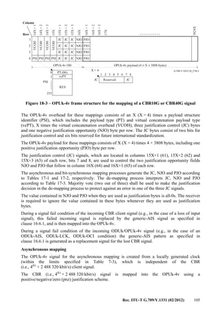
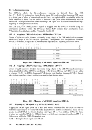
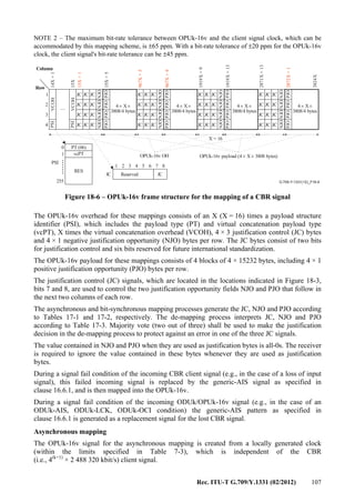
![108 Rec. ITU-T G.709/Y.1331 (02/2012)
The CBR (i.e., 4(k+1)
× 2 488 320 kbit/s) signal is mapped into the OPUk-16v using a
positive/negative/zero (pnz) justification scheme.
Bit-synchronous mapping
The OPUk-16v clock for the bit-synchronous mapping is derived from the CBR client signal.
During signal fail conditions of the incoming CBR signal (e.g., in the case of a loss of input signal),
the OPUk-16v payload signal bit rate shall be within the limits specified in Table 7-3 and neither a
frequency nor frame phase discontinuity shall be introduced. The resynchronization on the
incoming CBR signal shall be done without introducing a frequency or frame phase discontinuity.
The CBR (i.e., 4(k+1)
× 2 488 320 kbit/s) signal is mapped into the OPUk-16v without using the
justification capability within the OPUk-16v frame: NJO contains four justification bytes, PJO
contains four data bytes, and the JC signal is fixed to 00.
18.2.2.1 Mapping a CBR40G signal (e.g., STM-256) into OPU1-16v
Groups of eight successive bits (not necessarily being a byte) of the CBR40G signal are mapped
into a data (D) byte of the OPU1-16v (see Figure 18-7). Four times per OPU1-16v row (and thus
sixteen times per OPU1-16v frame), it is possible to perform either a positive or a negative
justification action.
....
G.709-Y.1331(12)_F18-7
Row#
Column #
X = 16
JC JC JC JCJC JC JC JC
NJO
NJO
NJO
NJO
NJO
NJO
NJO
NJO
NJO
NJO
NJO
NJO
NJO
NJO
NJO
NJO
JC JC JC JCJC JC JC JCJC JC JC JC
JC JC JC JCJC JC JC JCJC JC JC JC
JC JC JC JCJC JC JC JCJC JC JC JC
PJO
PJO
PJO
PJO
PJO
PJO
PJO
PJO
PJO
PJO
PJO
PJO
PJO
PJO
PJO
PJO
14X+1
15X
15X+1
967X+5
1919X+9
2871X+13
15X+5
967X+9
1919X+13
2872X+1
3824X
1
2
3
4
PSI
PSI
VCOH
VCOH
JC JC JC JC
15231D 15231D
15231D
15231D
15231D
15231D
15231D
15231D
15231D
15231D
15231D
15231D
15231D
15231D
15231D
15231D
Figure 18-7 – Mapping of a CBR40G signal into OPU1-16v
18.2.3 Mapping of an ATM cell stream into OPUk-Xv
A constant bit rate ATM cell stream with a capacity that is identical to the OPUk-Xv payload area is
created by multiplexing the ATM cells of a set of ATM VP signals. Rate adaptation is performed as
part of this cell stream creation process by either inserting idle cells or by discarding cells. Refer to
[ITU-T I.432.1]. The ATM cell stream is mapped into the OPUk-Xv payload area with the ATM
cell byte structure aligned to the OPUk-Xv payload byte structure (see Figure 18-8). The ATM cell
boundaries are thus aligned with the OPUk-Xv payload byte boundaries. Since the OPUk-Xv
payload capacity (X × 15232 bytes) is not an integer multiple of the cell length (53 bytes), a cell
may cross an OPUk-Xv frame boundary.](https://image.slidesharecdn.com/dd175b1f-a76f-4140-ae81-1f3e866587da-160607171351/85/T-REC-G-709-201202-I-PDF-E-116-320.jpg)
![Rec. ITU-T G.709/Y.1331 (02/2012) 109
...........
G.709-Y.1331(12)_F18-8
..... .....
..... .....
.......
OPUk-Xv overhead
OPUk-Xv payload
ATM cell
53 bytes
RES RES
RES
RES
RES
RES
RES
RES
14X+1
14X+2
15X
15X+1
15X+2
16X+1
3824X
16X
1
2
3
4 PSI PSI
VCOH
VCOH
0
255
RES
PT (06)
vcPT1
PSI
Figure 18-8 – OPUk-Xv frame structure and mapping of ATM cells into OPUk-Xv
The ATM cell information field (48 bytes) shall be scrambled before mapping into the OPUk-Xv.
In the reverse operation, following termination of the OPUk-Xv signal, the ATM cell information
field will be descrambled before being passed to the ATM layer. A self-synchronizing scrambler
with generator polynomial x43
+ 1 shall be used (as specified in [ITU-T I.432.1]). The scrambler
operates for the duration of the cell information field. During the 5-byte header the scrambler
operation is suspended and the scrambler state retained. The first cell transmitted on start-up will be
corrupted because the descrambler at the receiving end will not be synchronized to the transmitter
scrambler. Cell information field scrambling is required to provide security against false cell
delineation and the cell information field replicating the OTUk and ODUk frame alignment signal.
When extracting the ATM cell stream from the OPUk-Xv payload area after the ODUk
terminations, the ATM cells must be recovered. The ATM cell header contains a header error
control (HEC) field, which may be used in a similar way to a frame alignment word to achieve cell
delineation. This HEC method uses the correlation between the header bits to be protected by the
HEC (32 bits) and the control bit of the HEC (8 bits) introduced in the header after computation
with a shortened cyclic code with generating polynomial g(x) = x8
+ x2
+ x + 1.
The remainder from this polynomial is then added to the fixed pattern "01010101" in order to
improve the cell delineation performance. This method is similar to conventional frame alignment
recovery where the alignment signal is not fixed but varies from cell to cell.
More information on HEC cell delineation is given in [ITU-T I.432.1].
The OPUk-Xv overhead for the ATM mapping consists of X times a payload structure identifier
(PSI), which includes the payload type (PT) and virtual concatenation payload type (vcPT), X times
three virtual concatenation overhead (VCOH) bytes and X times four bytes reserved for future
international standardization (RES).
The OPUk-Xv payload for the ATM mapping consists of 4X × 3808 bytes.
18.2.4 Mapping of GFP frames into OPUk-Xv
The mapping of generic framing procedure (GFP) frames is performed by aligning the byte
structure of every GFP frame with the byte structure of the OPUk-Xv payload (see Figure 18-9).
Since the GFP frames are of variable length (the mapping does not impose any restrictions on the
maximum frame length), a GFP frame may cross the OPUk frame boundary. A GFP frame consists
of a GFP header and a GFP payload area.](https://image.slidesharecdn.com/dd175b1f-a76f-4140-ae81-1f3e866587da-160607171351/85/T-REC-G-709-201202-I-PDF-E-117-320.jpg)
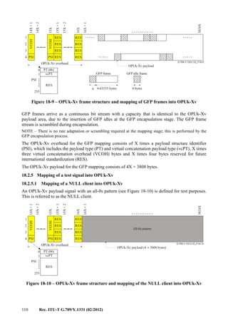
![Rec. ITU-T G.709/Y.1331 (02/2012) 111
The OPUk-Xv overhead for the NULL mapping consists of X times a payload structure identifier
(PSI), which includes the payload type (PT) and virtual concatenation payload type (vcPT), X times
three virtual concatenation overhead (VCOH) bytes and X times four bytes reserved for future
international standardization (RES).
The OPUk-Xv payload for the NULL mapping consists of 4X × 3808 bytes.
18.2.5.2 Mapping of PRBS test signal into OPUk-Xv
For test purposes, a 2 147 483 647-bit pseudo-random test sequence (231
– 1) as specified in
clause 5.8 of [ITU-T O.150] can be mapped into the OPUk-Xv payload. Groups of eight successive
bits of the 2 147 483 647-bit pseudo-random test sequence signal are mapped into eight data bits
(8D) (i.e., one byte) of the ODU3 payload (see Figure 18-11).
...........
G.709-Y.1331(12)_F18-11
.......
OPUk-Xv overhead
OPUk-Xv payload
RES RES
RES
RES
RES
RES
RES
RES
14X+1
14X+2
15X
15X+1
15X+2
16X+1
3824X
16X
1
2
3
4 PSI PSI
VCOH
VCOH
0
255
RES
PT (06)
vcPT1
PSI
X 3808 8D× ×
X 3808 8D× ×
X 3808 8D× ×
X 3808 8D× ×
Figure 18-11 – OPUk-Xv frame structure and mapping of 2 147 483 647-bit
pseudo-random test sequence into OPUk-Xv
The OPUk-Xv overhead for the PRBS mapping consists of X times a payload structure identifier
(PSI), which includes the payload type (PT) and virtual concatenation payload type (vcPT), X times
three virtual concatenation overhead (VCOH) bytes and X times four bytes reserved for future
international standardization (RES).
The OPUk-Xv payload for the PRBS mapping consists of 4X × 3808 bytes.
18.2.6 Mapping of a non-specific client bit stream into OPUk-Xv
In addition to the mappings of specific client signals as specified in the other subclauses of this
clause, a non-specific client mapping into OPUk-Xv is specified. Any (set of) client signal(s),
which after encapsulation into a continuous bit stream with a bit rate of the OPUk-Xv payload can
be mapped into the OPUk-Xv payload (see Figure 18-12). The bit stream must be synchronous with
the OPUk-Xv signal. Any justification must be included in the continuous bit stream creation
process. The continuous bit stream must be scrambled before mapping into the OPUk-Xv payload.](https://image.slidesharecdn.com/dd175b1f-a76f-4140-ae81-1f3e866587da-160607171351/85/T-REC-G-709-201202-I-PDF-E-119-320.jpg)
![112 Rec. ITU-T G.709/Y.1331 (02/2012)
...........
G.709-Y.1331(12)_F18-12
.......
OPUk-Xv overhead
OPUk-Xv payload (4X 3808 bytes)×
CS
CS
CS
CS
CS
CS
CS
CS
14X+1
14X+2
15X
15X+1
15X+2
16X+1
3824X
16X
1
2
3
4 PSI PSI
VCOH
VCOH
0
255
RES
PT (06)
vcPT1
PSI
Figure 18-12 – OPUk-Xv frame structure for the mapping
of a synchronous constant bit stream
The OPUk-Xv overhead for the mapping consists of X times a payload structure identifier (PSI),
which includes the payload type (PT) and virtual concatenation payload type (vcPT), X times three
virtual concatenation overhead (VCOH) bytes and X times four bytes for client specific purposes
(CS). The definition of these CS overhead bytes is performed within the encapsulation process
specification.
The OPUk-Xv payload for this non-specific mapping consists of 4X × 3808 bytes.
18.2.6.1 Mapping bit stream with octet timing into OPUk-Xv
If octet timing is available, each octet of the incoming data stream will be mapped into a data byte
(octet) of the OPUk-Xv payload.
18.2.6.2 Mapping bit stream without octet timing into OPUk-Xv
If octet timing is not available, groups of eight successive bits (not necessarily an octet) of the
incoming data stream will be mapped into a data byte (octet) of the OPUk-Xv payload.
18.3 LCAS for virtual concatenation
Refer to [ITU-T G.7042].
19 Mapping ODUj signals into the ODTU signal and the ODTU into the HO OPUk
tributary slots
This clause specifies the multiplexing of:
– ODU0 into HO OPU1, ODU1 into HO OPU2, ODU1 and ODU2 into HO OPU3 using
client/server specific asynchronous mapping procedures (AMP);
– other ODUj into HO OPUk using a client agnostic generic mapping procedure (GMP).
This ODUj into HO OPUk multiplexing is performed in two steps:
1) asynchronous mapping of ODUj into optical channel data tributary unit (ODTU) using
either AMP or GMP;
2) byte-synchronous mapping of ODTU into one or more HO OPUk tributary slots.](https://image.slidesharecdn.com/dd175b1f-a76f-4140-ae81-1f3e866587da-160607171351/85/T-REC-G-709-201202-I-PDF-E-120-320.jpg)
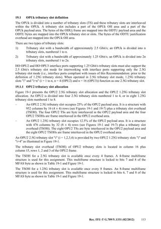

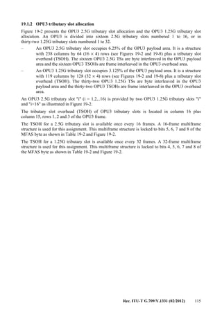
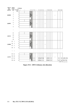
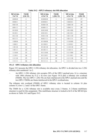
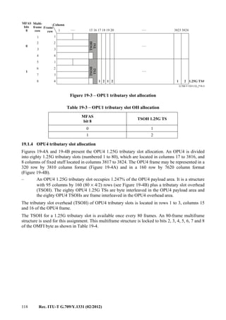
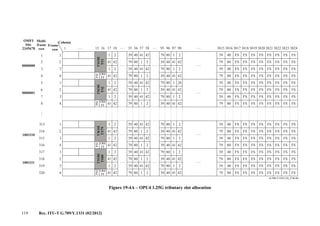
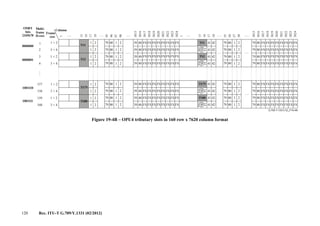
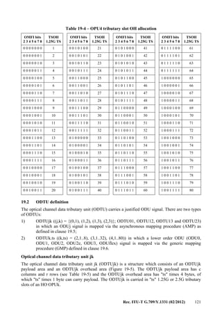
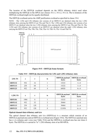
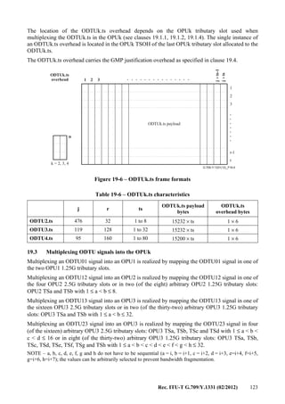
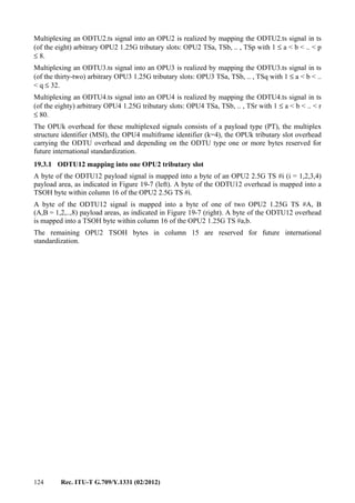
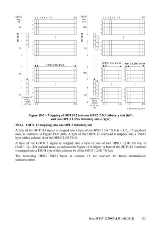
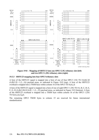

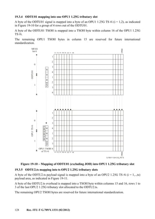
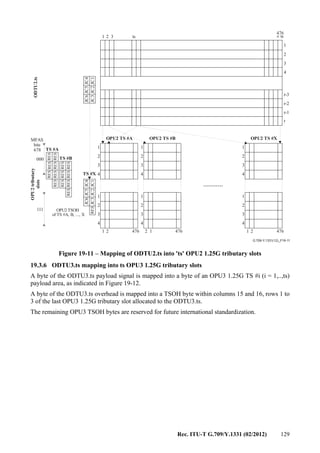
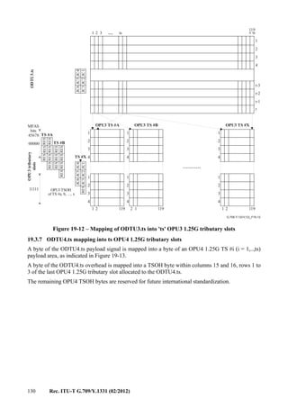
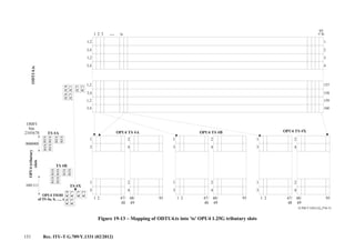
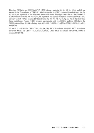
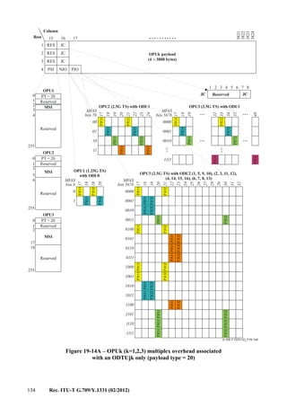
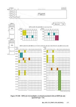
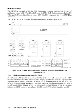
![Rec. ITU-T G.709/Y.1331 (02/2012) 137
19.4.1.1 OPU2 multiplex structure identifier (MSI) – Payload type 20
For the 4 OPU2 2.5G tributary slots four bytes of the PSI are used (PSI[2] .. PSI[5]) as MSI bytes as
shown in Figures 19-14A and 19-15. The MSI indicates the ODTU content of each tributary slot of
the OPU2. One byte is used for each tributary slot.
– The ODTU type in bits 1 and 2 is fixed to 00 to indicate the presence of an ODTU12.
– The tributary port # indicates the port number of the ODU1 that is being transported in this
2.5G TS; the assignment of ports to tributary slots is fixed, the port number equals the
tributary slot number.
1 2 3 4 5 6 7 8
PSI[2] 00 00 0000 TS1
PSI[3] 00 00 0001 TS2
PSI[4] 00 00 0010 TS3
PSI[5] 00 00 0011 TS4
Figure 19-15 – OPU2-MSI coding – Payload type 20
19.4.1.2 OPU3 multiplex structure identifier (MSI) – Payload type 20
For the 16 OPU3 2.5G tributary slots 16 bytes of the PSI are used (PSI[2] .. PSI[17]) as MSI bytes
as shown in Figures 19-14A, 19-16A and 19-16B. The MSI indicates the ODTU content of each
tributary slot of the OPU3. One byte is used for each tributary slot.
– The ODTU type in bits 1 and 2 indicates if the OPU3 TS is carrying ODTU13 or ODTU23.
The default ODTU type is ODTU13; it is present when either a tributary slot carries an
ODTU13, or is not allocated to carry an ODTU. Refer to Appendix V for some examples.
– The tributary port # in bits 3 to 8 indicates the port number of the ODTU13/23 that is being
transported in this 2.5G TS; for the case of ODTU23, a flexible assignment of tributary
ports to tributary slots is possible, for the case of ODTU13, this assignment is fixed, the
tributary port number equals the tributary slot number. ODTU23 tributary ports are
numbered 1 to 4.
1 2 3 4 5 6 7 8
PSI[2] ODTU type Tributary Port # TS1
PSI[3] ODTU type Tributary Port # TS2
PSI[4] ODTU type Tributary Port # TS3
PSI[5] ODTU type Tributary Port # TS4
PSI[6] ODTU type Tributary Port # TS5
PSI[7] ODTU type Tributary Port # TS6
PSI[8] ODTU type Tributary Port # TS7
PSI[9] ODTU type Tributary Port # TS8
PSI[10] ODTU type Tributary Port # TS9
PSI[11] ODTU type Tributary Port # TS10
PSI[12] ODTU type Tributary Port # TS11
PSI[13] ODTU type Tributary Port # TS12
PSI[14] ODTU type Tributary Port # TS13
PSI[15] ODTU type Tributary Port # TS14
PSI[16] ODTU type Tributary Port # TS15
PSI[17] ODTU type Tributary Port # TS16
Figure 19-16A – OPU3-MSI coding – Payload type 20](https://image.slidesharecdn.com/dd175b1f-a76f-4140-ae81-1f3e866587da-160607171351/85/T-REC-G-709-201202-I-PDF-E-145-320.jpg)
![138 Rec. ITU-T G.709/Y.1331 (02/2012)
1 2 3 4 5 6 7 8
PSI[1+ i] ODTU type Tributary Port # TS #i
00: ODTU13
01: ODTU23
10: Reserved
11: Reserved
00 0000: Tributary Port 1
00 0001: Tributary Port 2
00 0010: Tributary Port 3
00 0011: Tributary Port 4
:
00 1111: Tributary Port 16
Figure 19-16B – OPU3 MSI coding – Payload type 20
19.4.1.3 OPU1 multiplex structure identifier (MSI) – Payload type 20
For the 2 OPU1 1.25G tributary slots 2 bytes of the PSI are used (PSI[2], PSI[3]) as MSI bytes as
shown in Figures 19-14A and 19-17. The MSI indicates the ODTU content of each tributary slot of
the OPU1. One byte is used for each tributary slot.
– The ODTU type in bits 1 and 2 is fixed to 11 to indicate the presence of an ODTU01.
– The tributary port # in bits 3 to 8 indicates the port number of the ODTU01 that is being
transported in this 1.25G TS; the assignment of ports to tributary slots is fixed, the port
number equals the tributary slot number.
1 2 3 4 5 6 7 8 1.25G TS
PSI[2] 11 00 0000 TS1
PSI[3] 11 00 0001 TS2
Figure 19-17 – OPU1 MSI coding – Payload type 20
19.4.1.4 OPU4 multiplex structure identifier (MSI) – Payload type 21
For the eighty OPU4 1.25G tributary slots 80 bytes of the PSI are used (PSI[2] to PSI[81]) as MSI
bytes as shown in Figures 19-14C, 19-18A and 19-18B. The MSI indicates the ODTU content of
each tributary slot of an OPU. One byte is used for each tributary slot.
– The TS occupation bit 1 indicates if the tributary slot is allocated or unallocated.
– The tributary port # in bits 2 to 8 indicates the port number of the ODTU4.ts that is being
transported in this TS; for the case of an ODTU4.ts carried in two or more tributary slots, a
flexible assignment of tributary port to tributary slots is possible. ODTU4.ts tributary ports
are numbered 1 to 80. The value is set to all-0s when the occupation bit has the value 0
(tributary slot is unallocated).
1 2 3 4 5 6 7 8 1.25G TS
PSI[2] TS occupied Tributary Port # TS1
PSI[3] TS occupied Tributary Port # TS2
PSI[4] TS occupied Tributary Port # TS3
PSI[5] TS occupied Tributary Port # TS4
PSI[6] TS occupied Tributary Port # TS5
PSI[7] TS occupied Tributary Port # TS6
PSI[8] TS occupied Tributary Port # TS7
PSI[9] TS occupied Tributary Port # TS8
: : : :
: : : :
PSI[81] TS occupied Tributary Port # TS80
Figure 19-18A – OPU4 1.25G TS MSI coding – Payload type 21](https://image.slidesharecdn.com/dd175b1f-a76f-4140-ae81-1f3e866587da-160607171351/85/T-REC-G-709-201202-I-PDF-E-146-320.jpg)
![Rec. ITU-T G.709/Y.1331 (02/2012) 139
1 2 3 4 5 6 7 8
PSI[1+ i] Occupation Tributary Port # TS #i
0 : Unallocated
1 : Allocated
000 0000: Tributary Port 1
000 0001: Tributary Port 2
000 0010: Tributary Port 3
000 0011: Tributary Port 4
:
100 1111: Tributary Port 80
Figure 19-18B – OPU4 MSI coding – Payload type 21
19.4.1.5 OPU2 multiplex structure identifier (MSI) – Payload type 21
For the eight OPU2 1.25G tributary slots 8 bytes of the PSI (PSI[2] to PSI[9]) are used as MSI
bytes as show in Figures 19-14B, 19-19A and 19-19B. The MSI indicates the ODTU content of
each tributary slot of an OPU. One byte is used for each tributary slot.
– The ODTU type in bits 1 and 2 indicates if the OPU2 1.25G TS is carrying an ODTU12 or
ODTU2.ts. The default ODTU type is 11 (unallocated); it is present when a tributary slot is
not allocated to carry an ODTU.
– The tributary port # in bits 3 to 8 indicates the port number of the ODTU that is being
transported in this TS; a flexible assignment of tributary ports to tributary slots is possible,
ODTU12 tributary ports are numbered 1 to 4, and ODTU2.ts tributary ports are numbered 1
to 8. The value is set to all-0s when the ODTU type has the value 11 (tributary slot is
unallocated).
1 2 3 4 5 6 7 8
PSI[2] ODTU type Tributary Port # TS1
PSI[3] ODTU type Tributary Port # TS2
PSI[4] ODTU type Tributary Port # TS3
PSI[5] ODTU type Tributary Port # TS4
PSI[6] ODTU type Tributary Port # TS5
PSI[7] ODTU type Tributary Port # TS6
PSI[8] ODTU type Tributary Port # TS7
PSI[9] ODTU type Tributary Port # TS8
Figure 19-19A – OPU2 MSI coding – Payload type 21
1 2 3 4 5 6 7 8
PSI[1+ i] ODTU type Tributary Port # TS #i
00: ODTU12
01: Reserved
10: ODTU2.ts
11: Unallocated
00 0000: Tributary Port 1
00 0001: Tributary Port 2
00 0010: Tributary Port 3
00 0011: Tributary Port 4
:
00 0111: Tributary Port 8
Figure 19-19B – OPU2 MSI coding – Payload type 21](https://image.slidesharecdn.com/dd175b1f-a76f-4140-ae81-1f3e866587da-160607171351/85/T-REC-G-709-201202-I-PDF-E-147-320.jpg)
![140 Rec. ITU-T G.709/Y.1331 (02/2012)
19.4.1.6 OPU3 with 1.25G tributary slots (payload type 21) multiplex structure identifier
(MSI)
For the thirty-two OPU3 1.25G tributary slots 32 bytes of the PSI (PSI[2] to PSI[33]) are used as
MSI bytes as shown in Figures 19-14B, 19-20A and 19-20B. The MSI indicates the ODTU content
of each tributary slot of an OPU. One byte is used for each tributary slot.
– The ODTU type in bits 1 and 2 indicates if the OPU3 1.25G TS is carrying an ODTU13,
ODTU23 or ODTU3.ts. The default ODTU type is 11 (unallocated); it is present when a
tributary slot is not allocated to carry an ODTU.
– The tributary port # in bits 3 to 8 indicates the port number of the ODTU that is being
transported in this TS; a flexible assignment of tributary ports to tributary slots is possible,
ODTU13 tributary ports are numbered 1 to 16, ODTU23 tributary ports are numbered 1 to
4 and ODTU3.ts tributary ports are numbered 1 to 32. The value is set to all-0s when the
ODTU type has the value 11 (tributary slot is unallocated).
1 2 3 4 5 6 7 8
PSI[2] ODTU type Tributary Port # TS1
PSI[3] ODTU type Tributary Port # TS2
PSI[4] ODTU type Tributary Port # TS3
PSI[5] ODTU type Tributary Port # TS4
PSI[6] ODTU type Tributary Port # TS5
: : : :
: : : :
PSI[33] ODTU type Tributary Port # TS32
Figure 19-20A – OPU3 MSI coding – Payload type 21
1 2 3 4 5 6 7 8
PSI[1+ i] ODTU type Tributary Port # TS #i
00: ODTU13
01: ODTU23
10: ODTU3.ts
11: Unallocated
00 0000: Tributary Port 1
00 0001: Tributary Port 2
00 0010: Tributary Port 3
00 0011: Tributary Port 4
:
01 1111: Tributary Port 32
Figure 19-20B – OPU3 MSI coding – Payload type 21
19.4.2 OPUk payload structure identifier reserved overhead (RES)
253 (OPU1), 251 or 247 (OPU2), 239 or 223 (OPU3) and 175 (OPU4) bytes are reserved in the
OPUk PSI for future international standardization. These bytes are located in PSI[1] and PSI[4]
(OPU1), PSI[6] or PSI[10] (OPU2), PSI[18] or PSI[34] (OPU3), PSI[82] (OPU4) to PSI[255] of the
OPUk overhead. These bytes are set to all-0s.
19.4.3 OPUk multiplex justification overhead (JOH)
Two mapping procedures are used for the mapping of ODUj: either the asynchronous mapping
procedure (AMP) or generic mapping procedure (GMP) into ODTUjk or ODTUk.ts, respectively.
AMP uses ODUj and OPUk specific fixed stuff and justification opportunity definitions (ODTUjk).
GMP uses ODUj and OPUk independent stuff and justification opportunity definitions (ODTUk.ts).
Stuff locations within an ODTUk.ts are determined by means of a formula which is specified
in clause 19.4.3.2.](https://image.slidesharecdn.com/dd175b1f-a76f-4140-ae81-1f3e866587da-160607171351/85/T-REC-G-709-201202-I-PDF-E-148-320.jpg)
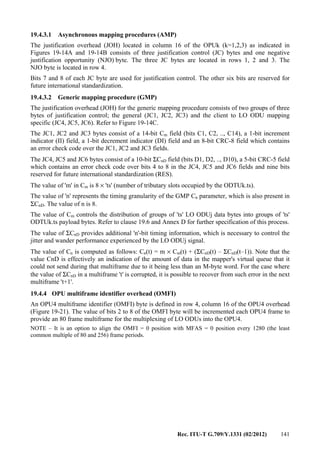
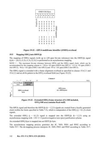
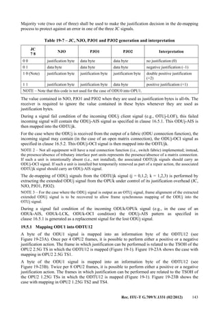
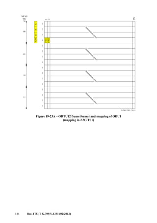
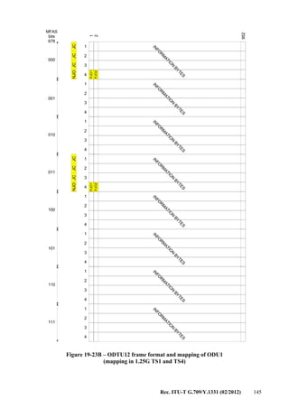
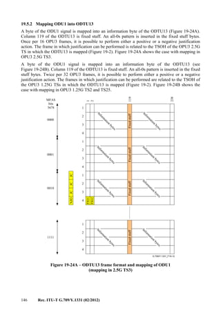
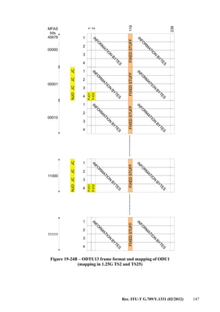
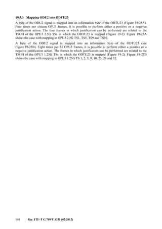
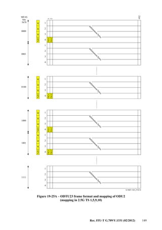
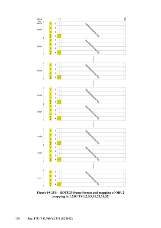
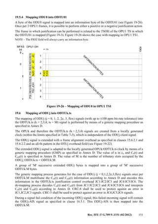
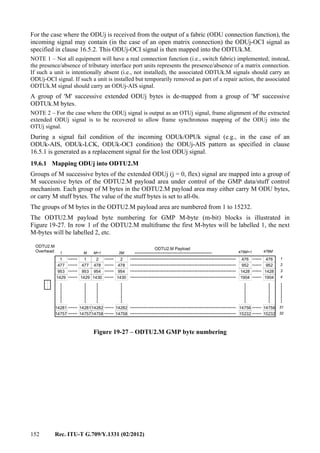

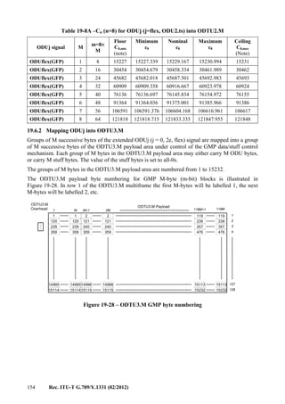
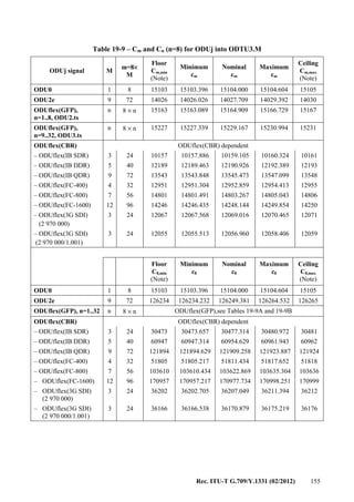
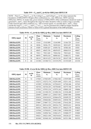
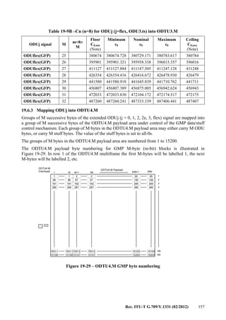
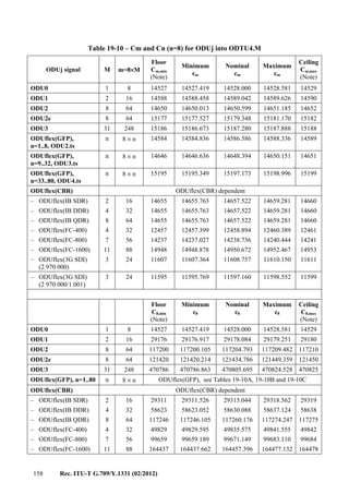
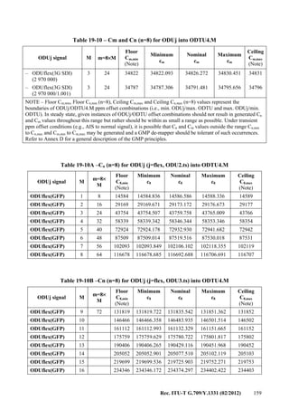
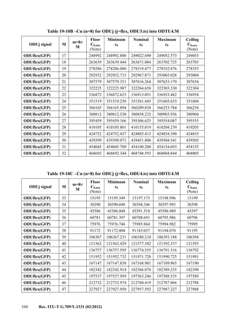
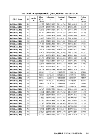

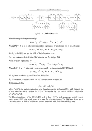
![164 Rec. ITU-T G.709/Y.1331 (02/2012)
Annex B
Adapting 64B/66B encoded clients via transcoding into 513B code blocks
(This annex forms an integral part of this Recommendation.)
Clients using 64B/66B coding can be adapted in a codeword and timing transparent mapping via
transcoding into 513B code blocks to reduce the bit rate that is required to transport the signal. The
resulting 513B blocks can be mapped in one of several ways depending on the requirements of the
client and the available bandwidth of the container into which the client is mapped. This mapping
can be applied to serial or parallel client interfaces.
B.1 Transmission order
The order of transmission of information in all the diagrams in this annex is first from left to right
and then from top to bottom.
B.2 Client frame recovery
For 40GBASE-R and 100GBASE-R clients, framing recovery consists of the recovering 64B/66B
block lock per the state diagram in Figure 82-10 of [IEEE 802.3ba]. For other 64B/66B encoded
clients, block lock is achieved as per the state diagram in Figure 49-12 of [IEEE 802.3].
Descrambling is performed as per the process shown in Figure 49-10 of [IEEE 802.3].
Each 66B codeword (after block lock) is one of the following:
− a set of eight data bytes with a sync header of "01";
− a control block (possibly including seven or fewer data octets) beginning with a sync
header of "10".
The 64 bits following the sync header are scrambled as a continuous bit-stream (skipping sync
headers and PCS lane markers) according to the polynomial G(x) = 1 + x39
+x58
. The 64B/66B PCS
receive process will descramble the bits other than (1) the sync header of 66B data and control
blocks, and (2) the PCS lane markers.
Figure B.1 illustrates the ordering of 64B/66B code blocks after the completion of the recovering
process for an interface.
Figure B.1 – Stream of 64B/66B code blocks for transcoding
1….…………….........66
1
2
x
3
Transmission order
Transmission order
66B Block
66B Block
66B Block
:
66B Block
:
1….…………….........66
1
2
x
3
Transmission order
Transmission order
66B Block
66B Block
66B Block
:
66B Block
66B Block
66B Block
66B Block
66B Block
66B Block
:
66B Block
:](https://image.slidesharecdn.com/dd175b1f-a76f-4140-ae81-1f3e866587da-160607171351/85/T-REC-G-709-201202-I-PDF-E-172-320.jpg)

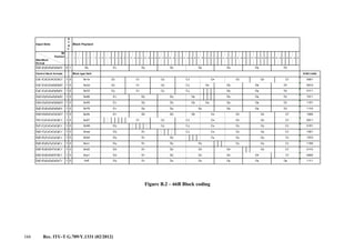
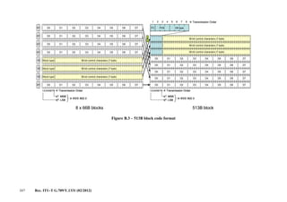
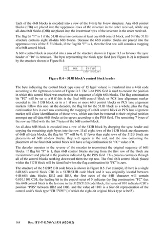
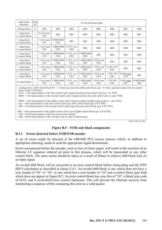
![Rec. ITU-T G.709/Y.1331 (02/2012) 171
Annex C
Adaptation of OTU3 and OTU4 over multichannel parallel interfaces
(This annex forms an integral part of this Recommendation.)
NOTE 1 – This mechanism is designed to allow the use of the optical modules being developed for IEEE
40GBASE-R and 100GBASE-R signals for short-reach client-side OTU3 and OTU4 interfaces respectively.
The corresponding physical layer specifications are being added to [ITU-T G.695] and [ITU-T G.959.1].
OTU3 signals may be carried over parallel interfaces consisting of four lanes.
OTU4 signals may be carried over parallel interfaces consisting of four or ten lanes, which are formed by bit
multiplexing of 20 logical lanes.
NOTE 2 – Ten lane IEEE 100GBASE-R interfaces have no corresponding ITU-T physical layer interface
specification.
The OTU3 and OTU4 frames are inversely multiplexed over physical/logical lanes on a 16-byte boundary
aligned with the OTUk frame as illustrated in Figure C.1. The OTUk frame is divided into 1020 groups of
16-bytes.
12241:12256
9161:9176
4081:4096
1:16 (FAS)
4
3
2
1
12257:12272
9177:9192
4097:5012
17:32
12273:12288
9193:9208
5013:5028
33:48
12289:13304
9209:9224
5029:5044
49:64
16305:16320
12225:12240
9145:9160
4065:4080
1 4080
Figure C.1 – OTU3 and OTU4 frames divided on 16-byte boundary
OTU3 16-byte increment distribution
Each 16-byte increment of an OTU3 frame is distributed round robin, to each of the four physical
lanes. On each OTU3 frame boundary the lane assignments are rotated.
For OTU3, the lane rotation and assignment is determined by the two LSBs of the MFAS as
described in Table C.1 and Figure C.2, which indicates the starting group of bytes of the OTU3
frame that are sent on each lane.
NOTE 3 – MFAS is scrambled as defined in clause 11.2.
The pattern repeats every 64 bytes until the end of the OTU3 frame. The following OTU3 frame
will use different lane assignments according to the MFAS.
Table C.1 – Lane rotation assignments for OTU3
MFAS 7-8 Lane 0 Lane 1 Lane 2 Lane 3
*00 1:16 17:32 33:48 49:64
*01 49:64 1:16 17:32 33:48
*10 33:48 49:64 1:16 17:32
*11 17:32 33:48 49:64 1:16](https://image.slidesharecdn.com/dd175b1f-a76f-4140-ae81-1f3e866587da-160607171351/85/T-REC-G-709-201202-I-PDF-E-179-320.jpg)
![172 Rec. ITU-T G.709/Y.1331 (02/2012)
The distribution of 16-byte blocks from the sequence of OTU3 frames is illustrated in Figure C.2:
The parallel lanes can be reassembled at the sink by first recovering framing on each of the parallel
lanes, then recovering the lane identifiers and then performing lane de-skewing. Frame alignment,
lane identifier recovery and multi-lane alignment should operate under 10–3
bit error rate conditions
before error correction. Refer to [ITU-T G.798] for the specific processing details.
The lane rotation mechanism will place the first 16 bytes of the OTU3 frame on each lane once per
4080 × 4 (i.e., 16320) bytes (the same as an OTU3 itself). The two LSBs of the MFAS will be the
same in each FAS on a particular lane, which allows the lane to be identified. Since the MFAS
cycles through 256 distinct values, the lanes can be de-skewed and reassembled by the receiver as
long as the total skew does not exceed 127 OTU3 frame periods (approximately 385 μs). The
receiver must use the MFAS to identify each received lane, as lane positions may not be preserved
by the optical modules to be used for this application.
OTU4 16-byte increment distribution
Each 16-byte increment of an OTU4 frame is distributed, round robin, to each of the 20 logical
lanes. On each OTU4 frame boundary the lane assignments are rotated.
For distribution of OTU4 to twenty logical lanes, since the MFAS is not a multiple of 20, a different
marking mechanism must be used. Since the frame alignment signal is 6 bytes (48 bits) and as per
[ITU-T G.798] only 32 bits must be checked for frame alignment, the third OA2 byte position will
be borrowed as a logical lane marker (LLM). For maximum skew detection range, the lane marker
value will increment on successive frames from 0-239 (240 values being the largest multiple of 20
that can be represented in 8-bits). LLM = 0 position shall be aligned with MFAS = 0 position every
3840 (the least common multiple of 240 and 256) frame periods. The logical lane number can be
recovered from this value by a modulo 20 operation. Table C.2 and Figure C.3 illustrate how bytes
of the OTU4 are distributed in 16-byte increments across the 20 logical lanes.
The pattern repeats every 320 bytes until the end of the OTU4 frame.
The following OTU4 frame will use different lane assignment according to the LLM MOD 20.
Table C.2 – Lane rotation assignments for OTU4
LLM MOD 20 Lane 0 Lane 1 ………………. Lane 18 Lane 19
0 1:16 17:32 289:304 305:320
1 305:320 1:16 273:288 289:304
:
18 33:48 49:64 1:16 17:32
19 17:32 33:48 305:320 1:16
The distribution of 16-byte blocks from the sequence of OTU4 frames is illustrated in Figure C.3:
The parallel lanes can be reassembled at the sink by first recovering framing on each of the parallel
lanes, then recovering the lane identifiers and then performing de-skewing of the lanes. Frame
alignment, lane identifier recovery and multi-lane alignment should operate under 10–3
bit error rate
conditions before error correction. Refer to [ITU-T G.798] for specific processing details.
The lane rotation mechanism will place the first 16 bytes of the OTU4 frame on each lane once per
4080×4 (i.e., 16320) bytes (the same as an OTU4 itself). The "LLM MOD 20" will be the same in
each FAS on a particular lane, which allows the lane to be identified. Since the LLM cycles through
240 distinct values, the lanes can be de-skewed and reassembled by the receiver as long as the total](https://image.slidesharecdn.com/dd175b1f-a76f-4140-ae81-1f3e866587da-160607171351/85/T-REC-G-709-201202-I-PDF-E-180-320.jpg)
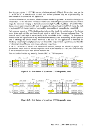
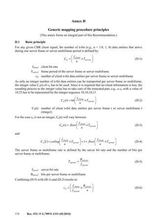
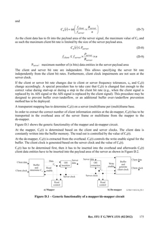
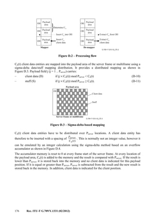
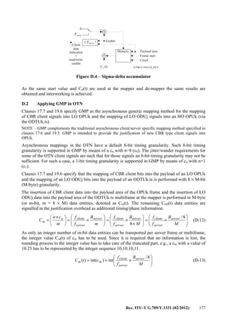

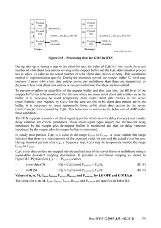
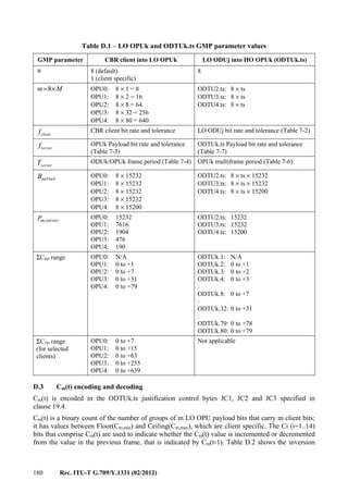
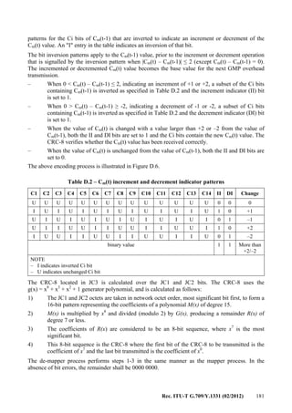
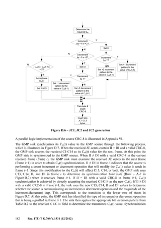
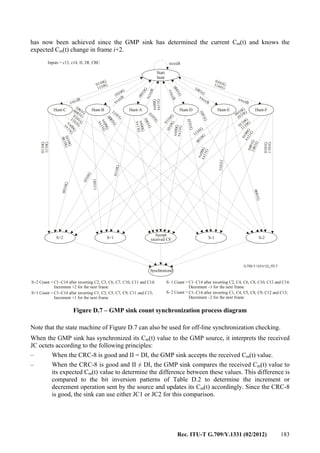
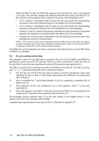
![Rec. ITU-T G.709/Y.1331 (02/2012) 185
Annex E
Adaptation of parallel 64B/66B encoded clients
(This annex forms an integral part of this Recommendation.)
E.1 Introduction
IEEE 40GBASE-R and 100GBASE-R interfaces specified in [IEEE 802.3ba]-2010 are parallel
interfaces intended for short-reach (up to 40 km) interconnection of Ethernet equipment. This annex
describes the process of converting the parallel format of these interfaces into a serial bit stream to
be carried over the OTN.
The order of transmission of information in all the diagrams in this annex is first from left to right
and then from top to bottom.
E.2 Clients signal format
40GBASE-R and 100GBASE-R clients are initially parallel interfaces, but in the future they may be
serial interfaces. Independent of whether these interfaces are parallel or serial, or what the parallel
interface lane count is, 40GBASE-R signals are comprised of four PCS lanes, and 100GBASE-R
signals are comprised of twenty PCS lanes. If the number of physical lanes on the interface is fewer
than the number of PCS lanes, the appropriate number of PCS lanes is bit-multiplexed onto each
physical lane of the interface. Each PCS lane consists of 64B/66B encoded data with a PCS lane
alignment marker inserted on each lane once per 16384 66-bit blocks. The PCS lane alignment
marker itself is a special format 66B codeword.
The use of this adaptation for 40GBASE-R into OPU3 also applies the transcoding method that
appears in Annex B and the framing method of Annex F. The adaptation described in this annex
alone can be used for the adaptation of 100GBASE-R into OPU4.
E.3 Client frame recovery
Client framing recovery consists of the following:
− bit-disinterleave the PCS lanes, if necessary. This is necessary whenever the number of
PCS lanes and the number of physical lanes is not equal, and is not necessary when they are
equal (e.g., a 4-lane 40GBASE-R interface);
− recover 64B/66B block lock as per the state diagram in Figure 82-10 of [IEEE 802.3ba];
− recover lane alignment marker framing on each PCS lane as per the state diagram in
Figure 82-11 of [IEEE 802.3ba];
− reorder and de-skew the PCS lanes into a serialized stream of 66B blocks (including lane
alignment markers). Figure E.1 illustrates the ordering of 66B blocks after the completion
of this process for an interface with p PCS lanes.](https://image.slidesharecdn.com/dd175b1f-a76f-4140-ae81-1f3e866587da-160607171351/85/T-REC-G-709-201202-I-PDF-E-193-320.jpg)
![186 Rec. ITU-T G.709/Y.1331 (02/2012)
Figure E.1 – De-skewed/serialized stream of 66B blocks
Each 66B codeword is one of the following:
− a set of eight data bytes with a sync header of "01";
− a control block (possibly including seven or fewer data octets) beginning with a sync
header of "10";
− a PCS lane alignment marker, also encoded with a sync header of "10". Of the 8 octets
following the sync header, 6 octets have fixed values allowing the PCS lane alignment
markers to be recognized (see Tables E.1 and E.2). The fourth octet following the sync
header is a BIP-8 calculated over the data from one alignment marker to the next as defined
in Table 82-4 of [IEEE 802.3ba]. The eighth octet is the complement of this BIP-8 value to
maintain DC balance. Note that the intended operation is to pass these BIP-8 values
transparently as they are used for monitoring the error ratio of the Ethernet link between
Ethernet PCS sublayers. For the case of 100GBASE-R, the BIP-8 values are not
manipulated by the mapping or de-mapping procedure. For the case of 40GBASE-R, a
BIP-8 compensation is done as described in clause E.4.1.
For all-data blocks and control blocks, the 64 bits following the sync header are scrambled as a
continuous bit-stream (skipping sync headers and PCS lane alignment markers) according to the
polynomial G(x) = 1 + x39
+x58
.
After 64B/66B block lock recovery as per the state diagram in Figure 82-10 of [IEEE 802.3ba] to
the single-lane received aggregate signal, these 66B blocks are re-distributed to PCS lanes at the
egress interface. The 66B blocks (including PCS lane alignment markers) resulting from the
decoding process are distributed round-robin to PCS lanes. If the number of PCS lanes is greater
than the number of physical lanes of the egress interface, the appropriate numbers of PCS lanes are
bit-multiplexed onto the physical lanes of the egress interface.
0……………………...65
1
2
p
p +1
p x 16384
:
Transmission order
Transmission order
Lane Marker 1
Lane Marker 2
:
Lane Marker p
p x 16383
66B blocks
p x 16383
66B blocks
:
Lane Marker p
Lane Marker 1
Lane Marker 2
Lane Marker 1
Lane Marker 2
:
Lane Marker p
:
Lane Marker p
p x 16383
66B blocks
p x 16383
66B blocks
:
Lane Marker p
Lane Marker 1
Lane Marker 2
Lane Marker 1
Lane Marker 2
:
Lane Marker p
:
Lane Marker p
p x 16383
66B blocks
1
2
p
p +1
p x 16384
:
Transmission order
Transmission order](https://image.slidesharecdn.com/dd175b1f-a76f-4140-ae81-1f3e866587da-160607171351/85/T-REC-G-709-201202-I-PDF-E-194-320.jpg)
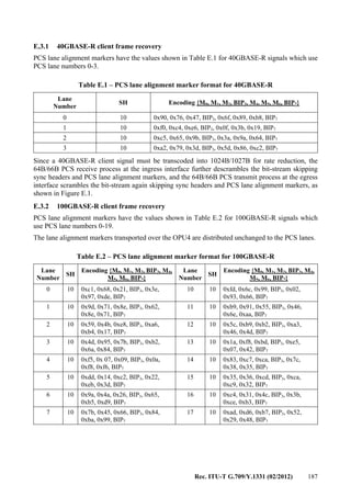
![188 Rec. ITU-T G.709/Y.1331 (02/2012)
Table E.2 – PCS lane alignment marker format for 100GBASE-R
Lane
Number
SH
Encoding {M0, M1, M2, BIP3, M4,
M5, M6, BIP7}
Lane
Number
SH
Encoding {M0, M1, M2, BIP3, M4,
M5, M6, BIP7}
8 10 0xa0, 0x24, 0x76, BIP3, 0x5f,
0xdb, 0x89, BIP7
18 10 0x5f, 0x66, 0x2a, BIP3, 0xa0,
0x99, 0xd5, BIP7
9 10 0x68, 0xc9, 0xfb, BIP3, 0x97,
0x36, 0x04, BIP7
19 10 0xc0, 0xf0, 0xe5, BIP3, 0x3f, 0x0f,
0x1a, BIP7
E.4 Additions to Annex B transcoding for parallel 64B/66B clients
When OPUk is large enough for the serialized 66B block stream (e.g., for 100GBASE-R client
signals into OPU4), the recovered client frames are adapted directly as per this annex.
When used in combination with the transcoding into 513B code blocks described in Annex B
(e.g., for 40GBASE-R client signals into OPU3), this clause describes the additions to the Annex B
transcoding process for transport of PCS lane alignment markers.
Ethernet path monitoring is the kind of behaviour that is desirable in the case where the Ethernet
equipment and the OTN equipment are in different domains (e.g., customer and service provider)
and from the standpoint of the Ethernet equipment. It is also the default behaviour which would
result from the current mapping of 100GBASE-R where the 66B blocks would be mapped into the
OPU4 container after management of skew. It may also be perceived as a transparency requirement
that BIP-8 work end-to-end. Additional functionality as described below has to be built in to allow
BIP-8 transparency for 40GBASE-R client signals.
PCS lane alignment markers are encoded together with 66B control blocks into the uppermost rows
of the 513B code block shown in Figure B.3. The flag bit "F" of the 513B structure is 1 if the 513B
structure contains at least one 66B control block or PCS lane alignment marker, and 0 if the 513B
structure contains eight all-data 66B blocks.
The transcoding into 512B/513B must encode PCS lane alignment marker into a row of the
structure shown in Figure B.3 as follows: The sync header of "10" is removed. The received M0, M1
and M2 bytes of the PCS alignment marker encodings as shown in Table E.1 are used to forward the
lane number information. The first byte of the row will contain the structure shown in Figure B.4,
with a CB-TYPE field of "0100". The POS field will indicate the position where the PCS lane
alignment marker was received among the group of eight 66B codewords being encoded into this
513B block. The flag continuation bit "FC" will indicate whether any other 66B control blocks or
PCS lane alignment markers are encoded into rows below this one in the 513B block. Beyond this
first byte, the next four bytes of the row are populated with the received M0, M1, M2 and ingress
BIP3 bytes of the PCS alignment marker encodings at the encoder. At the decoder, a PCS lane
alignment marker will be generated in the position indicated by the POS field among any 66B
all-data blocks contained in this 513B block, the sync header of "10" is generated followed by the
received M0, M1 and M2 bytes, the egress BIP3 byte, the bytes M4, M5 and M6 which are the
bit-wise inverted M0, M1 and M2 bytes received at the decoder, and the egress BIP7 byte which is
the bit-wise inverted egress BIP3 byte.
It will then be up to the Ethernet receiver to handle bit errors within the OTN section that might
have altered the PCS alignment marker encodings (for details refer to clause 82.2.18.3 and
Figure 82-11 in [IEEE 802.3ba]).
The egress BIP3 and the egress BIP7 bytes are calculated as described in clause E.4.1.](https://image.slidesharecdn.com/dd175b1f-a76f-4140-ae81-1f3e866587da-160607171351/85/T-REC-G-709-201202-I-PDF-E-196-320.jpg)
![Rec. ITU-T G.709/Y.1331 (02/2012) 189
Figure E.2 below shows the transcoded lane marker format.
Figure E.2 – Transcoded lane marker format
E.4.1 BIP-8 transparency
The transcoding method used for 40GBASE-R is timing and PCS codeword transparent. In normal
operation, the only aspects of the PCS encoded bitstream that are not preserved given the mapping
described in annexes B, E and F are for one the scrambling, since the scrambler does not begin with
a known state and multiple different encoded bitstreams can represent the same PCS encoded
content, and secondly the BIP-8 value in the Ethernet path or more precisely, the bit errors that
occur between the Ethernet transmitter and the ingress point of the OTN domain and within the
OTN domain. The BIP-8 values can be preserved with the scheme described below. As the
scrambling itself does not contain any information that has to be preserved, no effort has been made
to synchronize the scrambler states between OTN ingress and OTN egress.
Unfortunately, since the BIP-8 is calculated on the scrambled bitstream, a simple transport of the
BIP-8 across the OTN domain in the transcoded lane marker will not result in a BIP-8 value that is
meaningful for detecting errors in the received, descrambled, transcoded, trans-decoded, and then
rescrambled bit stream.
To preserve the bit errors between the Ethernet transmitter and the egress side of the OTN domain,
the bit-error handling is divided into two processes, one that takes place at the OTN ingress side, or
encoder, and one on the OTN egress side, or decoder.
At the OTN ingress an 8-bit error mask is calculated by generating the expected BIP-8 for each PCS
lane and XORing this value with the received BIP-8. This error mask will have a "1" for each bit of
the BIP-8 which is wrong, and a "0" for each bit which is correct. This value is shown as a PCS
BIP-8 error mask in Figure E.2.
In the event no errors are introduced across the OTN (as an FEC protected network can be an
essentially zero error environment), the PCS BIP-8 error mask can be used to adjust the newly
calculated PCS BIP-8 at the egress providing a reliable indication of the number of errors that are
introduced across the full Ethernet path. If errors are introduced across the OTN, this particular
BIP-8 calculation algorithm will not see these errors.
To overcome this situation, a new BIP-8 per lane for the OTN section is introduced. In the
following this new BIP-8 will be identified as OTN BIP-8 in order to distinguish it from the
PCS BIP-8.
It should be noted that the term OTN BIP-8 does not refer to and should not be confused with the
BIP-8 defined in the OTUk overhead (byte SM[2]).](https://image.slidesharecdn.com/dd175b1f-a76f-4140-ae81-1f3e866587da-160607171351/85/T-REC-G-709-201202-I-PDF-E-197-320.jpg)
![190 Rec. ITU-T G.709/Y.1331 (02/2012)
The OTN BIP-8 is calculated similarly to the PCS BIP-8 as described in clause 82.2.8 of
[IEEE 802.3ba] with the exception that the calculation will be done over unscrambled PCS lane
data, the original received lane alignment marker, after error control block insertion and before
transcoding. Figure E.2 shows the byte location of the OTN BIP-8 in the transcoded lane marker.
The transcoded lane marker is transmitted together with the transcoded data blocks over the OTN
section as defined in Annex B. At the OTN egress after trans-decoding and before scrambling, the
ingress alignment marker is recreated using M0, M1, M2 and ingress BIP3 of the transcoded
alignment marker followed by the bit-wise inversion of these bytes. This recreated alignment
marker together with the trans-decoded and unscrambled data blocks is used to calculate the
expected OTN BIP-8 for each PCS lane (refer to clause 82.2.8 of [IEEE 802.3ba]). The expected
value will be XORed with the received OTN BIP-8. This error mask will have a "1" for each bit of
the OTN BIP-8 which is wrong, and a "0" for each bit which is correct.
The egress BIP3 for each PCS lane is calculated over the trans-decoded and scrambled data blocks
including the trans-decoded alignment marker (refer to clause E.4) following the process depicted in
clause 82.2.8 of [IEEE 802.3ba].
The egress BIP3 is then adjusted for the errors that occurred up to the OTN egress by first XORing
with the PCS BIP-8 error mask and then XORing with the OTN BIP-8 error mask. This combined
error mask will be used to compute the number of BIP errors when used for non-intrusive
monitoring.
The BIP7 is created by bit-wise inversion of the adjusted BIP3.
E.4.2 Errors detected by mapper
Errors encountered before the mapper, such as loss of client signal on any physical lane of the
interface, will result in the insertion of an Ethernet LF sequence ordered set prior to this process.
The same action should be taken as a result of failure to achieve 66B block lock on any PCS lane,
failure to achieve lane alignment marker framing on each PCS lane, or failure to de-skew because
the skew exceeds the buffer available for de-skew.
An invalid 66B block will be converted to an error control block before transcoding. An invalid
66B block is one which does not have a sync header of "01" or "10", or one which has a sync
header of "10", is not a valid PCS lane alignment marker and has a control block type field which
does not appear in Figure B.2 or has one of the values 0x2d, 0x33, 0x66, or 0x55 which are not used
for 40GBASE-R or 100GBASE-R. An error control block has sync bits of "10", a block type code
of 0x1e, and 8 seven-bit/E/error control characters. This will prevent the Ethernet receiver from
interpreting a sequence of bits containing this error as a valid packet.
E.4.3 Errors detected by de-mapper
Several mechanisms will be employed to reduce the probability that the de-mapper constructs
erroneous parallel 64B/66B encoded data at the egress if bit errors have corrupted. Since detectable
corruption normally means that the proper order of 66B blocks to construct at the de-mapper cannot
be reliably determined, if any of these checks fail, the de-mapper will transmit eight 66B error
control blocks (sync="10", control block type=0x1e, and eight 7-bit/E/control characters).
Mechanisms for improving the robustness and for 513B block lock including PCS lane alignment
markers are discussed in Annex F.](https://image.slidesharecdn.com/dd175b1f-a76f-4140-ae81-1f3e866587da-160607171351/85/T-REC-G-709-201202-I-PDF-E-198-320.jpg)
![Rec. ITU-T G.709/Y.1331 (02/2012) 191
Annex F
Improved robustness for mapping of 40GBASE-R
into OPU3 using 1027B code blocks
(This annex forms an integral part of this Recommendation.)
F.1 Introduction
When a parallel 40GBASE-R signal is transcoded as per annexes B and E and directly mapped into
OPU3 without GFP framing, another method is needed to locate the start of 513B blocks and to
provide protection to prevent bit errors creating an unacceptable increase in mean time to false
packet acceptance (MTTFPA).
F.2 513B code block framing and flag bit protection
The mapping of 513B code blocks into OPU3 requires a mechanism for locating the start of the
code blocks. A mechanism is also needed to protect the flag bit, whose corruption could cause data
to be erroneously interpreted as control and vice versa.
Both of these requirements can be addressed by providing parity across the flag bits of two 513B
blocks produced from the transcoding of Annex B.
Figure F.1 illustrates the flag parity bit across two 513B blocks. This creates a minimum two-bit
Hamming distance between valid combinations of flag bits.
G.709-Y.1331(12)_FF.1
F F512 512
Flag parity bit
512 bit payload (8 66b block)
1,024 bit payload (2 8 66b block)
×
× ×
Data
Data
Control
Control
1
1
1
1 1 1
0
00
0 0
0
Scramble
F 512FP
Data
Data
Control
Control
512
Figure F.1 – Flag parity bit on two 513B blocks (1027B code)
The flag parity bit creates a sequence that can be used for framing to locate the 513B blocks in a
stream of bits. The state diagram of Figure 49-12 of [IEEE 802.3] is applied to locate a 3-bit pattern
appearing once per 1027 bits (rather than a 2-bit pattern appearing once per 66 bits) where four out
of eight 3-bit sequences (rather than two out of four two-bit values as used in IEEE 802.3) match
the pattern. The additional step required is to scramble the non-flag bits so that the legal sequences
of these bits are not systematically mimicked in the data itself. The scrambler to be used for this
purpose is the Ethernet self-synchronous scrambler using the polynomial G(x) = 1 + x39
+ x58
.](https://image.slidesharecdn.com/dd175b1f-a76f-4140-ae81-1f3e866587da-160607171351/85/T-REC-G-709-201202-I-PDF-E-199-320.jpg)
![192 Rec. ITU-T G.709/Y.1331 (02/2012)
At the de-mapper, invalid flag bit parity will cause both of the 513B blocks across which the flag bit
parity applies to be decoded as 8 × 2 66B error control blocks ("10" sync header, control block type
0x1e, followed by eight 7-bit/E/control characters).
F.3 66B block sequence check
Bit error corruption of the position or flag continuation bits could cause 66B blocks to be
de-mapped from 513B code blocks in the incorrect order. Additional checks are performed to
prevent that this results in incorrect packet delineation. Since detectable corruption normally means
that the proper order of 66B blocks to construct at the decoder cannot be reliably determined, if any
of these checks fail, the decoder will transmit eight 66B error control blocks (sync="10", control
block type=0x1e, and eight 7-bit/E/control characters).
Other checks are performed to reduce the probability that invalid data is delivered at the egress in
the event that bit errors have corrupted any of the POS fields or flag continuation bits "FC".
If flag bit "F" is 1 (i.e., the 513B block includes at least one 64B/66B control block), for the rows of
the table up until the first one with a flag continuation bit of zero (the last one in the block), it is
verified that no two 66B control blocks or lane alignment markers within that 513B block have the
same value in the POS field, and further, that the POS field values for multiple control or lane
alignment rows are in ascending order, which will always be the case for a properly constructed
513B block. If this check fails, the 513B block is decoded into eight 66B error control blocks.
The next check is to ensure that the block sequence corresponds to well-formed packets, which can
be done according to the state diagram in Figures F.2 and F.3. This check will determine if 66B
blocks are in an order that does not correspond to well-formed packets, e.g., if during an IPG an
all-data 66B block is detected without first seeing a control block representing packet start, or if
during a packet a control/idle block is detected without first seeing a control block representing
packet termination, control blocks have likely been misordered by corruption of either the POS bits
or a flag continuation bit. Failure of this check will cause the 513B block to be decoded as eight
66B error control blocks. Note that PCS lane alignment markers are accepted in either state and do
not change state as shown in Figure F.3.
The sequence of PCS lane alignment markers is also checked at the decoder. For an interface with p
PCS lanes, the PCS lane alignment markers for lanes 0 to p-1 will appear in a sequence, followed
by 16383×p non-lane-marker 66B blocks, followed by another group of PCS lane alignment
markers. A counter is maintained at the decoder to keep track of when the next group of lane
alignment markers is expected. If, in the process of decoding lane alignment markers from a 513B
block, a lane alignment marker is found in a position where it is not expected, or a lane alignment
marker is missing in a position where it would have been expected, the entire 513B block is
decoded as eight 66B error control blocks as shown in Figures F.2, F.3, and F.4.
F.3.1 State diagram conventions
The body of this clause is comprised of state diagrams, including the associated definitions of
variables, constants, and functions. Should there be a discrepancy between a state diagram and
descriptive text, the state diagram prevails.
The notation used in the state diagrams follows the conventions of clause 21.5 of [IEEE 802.3].
State diagram timers follow the conventions of clause 14.2.3.2 of [IEEE 802.3]. The notation ++
after a counter or integer variable indicates that its value is to be incremented.](https://image.slidesharecdn.com/dd175b1f-a76f-4140-ae81-1f3e866587da-160607171351/85/T-REC-G-709-201202-I-PDF-E-200-320.jpg)
![Rec. ITU-T G.709/Y.1331 (02/2012) 193
F.3.2 State variables
F.3.2.1 Constants
EBLOCK_T<65:0>
66-bit vector to be sent to the PCS containing /E/ in all the eight character locations.
Mi<65:0>
66-bit vector containing the trans-decoded alignment marker of i-th PCS lane (0 < i ≤ p).
(p=4 for 40GBASE-R, and p=20 for 100GBASE-R).
F.3.2.2 Variables
1027B_block_lock
Indicates the state of the block_lock variable when the state diagram of Figure 49-12 of
[IEEE 802.3] is applied to locate a 3-bit pattern appearing once per 1027 bits (rather than a
2-bit pattern appearing once per 66 bits) as described in clause F.2. Set true when sixty-four
contiguous 1027-bit blocks are received with valid 3-bit patterns, set false when sixteen
1027-bit blocks with invalid 3-bit patterns are received before sixty-four valid blocks.
1027B_high_ber
Indicates a Boolean variable when the state diagram of Figure 49-13 of [IEEE 802.3] is
applied to count invalid 3-bit sync headers of 1027-bit blocks (rather than 2-bit sync
headers of 66-bit blocks) within the current 250 μs (rather than 125 μs). Set true when the
ber_cnt exceeds 8 (rather than 16) indicating a bit error ratio >10–4
.
Mseq_violation
Indicates a Boolean variable that is set and latched in each rx513_raw<527:0> PCS lane
alignment marker cycle based on the PCS lane marker position and order. It is true if the
unexpected marker sequence is detected and false if not.
POS_violation
A Boolean variable that is set in each rx513_raw<527:0> based on the POS field values for
rx_tcd<65:0>. It is true if the two or more have the same POS values or if they are not in
ascending order, and false if their POS values are in ascending order.
reset
A Boolean variable that controls the resetting of the PCS. It is true whenever a reset is
necessary including when reset is initiated from the MDIO, during power on, and when the
MDIO has put the PCS into low-power mode.
Rx513_coded<512:0>
A vector containing the input to the 512B/513B decoder.
rx513_raw<527:0>
A vector containing eight successive 66-bit vectors (tx_coded).
rx_tcd<65:0>
A 66-bit vector transcode-decoded from a 513-bit block following the rules shown in
Figure B.5.](https://image.slidesharecdn.com/dd175b1f-a76f-4140-ae81-1f3e866587da-160607171351/85/T-REC-G-709-201202-I-PDF-E-201-320.jpg)
![194 Rec. ITU-T G.709/Y.1331 (02/2012)
seq_violation
A Boolean variable that is set in each rx513_raw<527:0> based on the sequence check on
an rx_tcd<65:0> stream. It is true if the unexpected sequence is detected and false if not.
F.3.2.3 Functions
DECODE(rx513_coded<512:0>)
Decodes the 513-bit vector returning rx513_raw<527 :0> which is sent to the client
interface. The DECODE function shall decode the block as specified in Figure F.2.
R_BLOCK_TYPE = {C, S, T, D, E, M}
This function classifies each 66-bit rx_tcd vector as belonging to one of the six types
depending on its contents.
Values: C, S, T, and D are defined in clause 49.2.13.2.3 of [IEEE 802.3].
M: the vector contains a sync header of 10 and is recognized as a valid PCS lane
alignment marker by using the state machine shown in Figure F.3.
E: the vector does not meet the criteria for any other value.
R_TYPE(rx_tcd<65:0>)
Returns the R_BLOCK_TYPE of the rx_tcd<65:0> bit vector.
R_TYPE_NEXT
Prescient end of packet check function. It returns the R_BLOCK_TYPE of the rx_tcd
vector immediately following the current rx_tcd vector.
F.3.2.4 Counters
cnt
Count up to a maximum of p of the number of PCS lanes.
F.3.3 State diagrams
The receive state machine for a series of 513-bit blocks shown in Figure F.2 determines whether the
513-bit block contains valid eight 66-bit blocks or not.](https://image.slidesharecdn.com/dd175b1f-a76f-4140-ae81-1f3e866587da-160607171351/85/T-REC-G-709-201202-I-PDF-E-202-320.jpg)
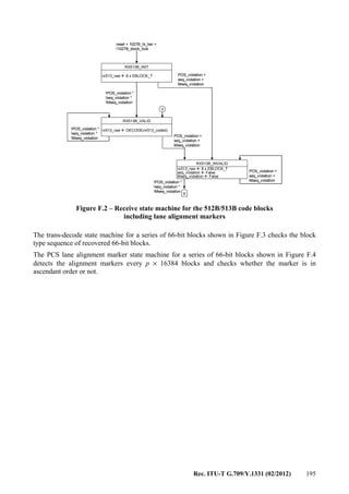
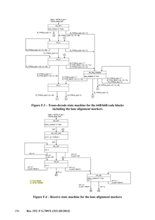
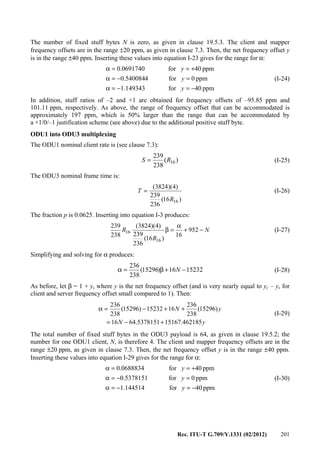
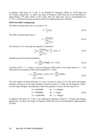
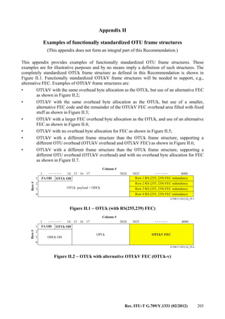
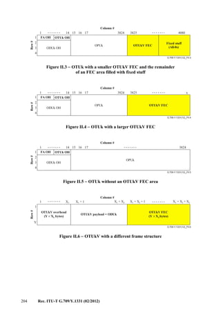
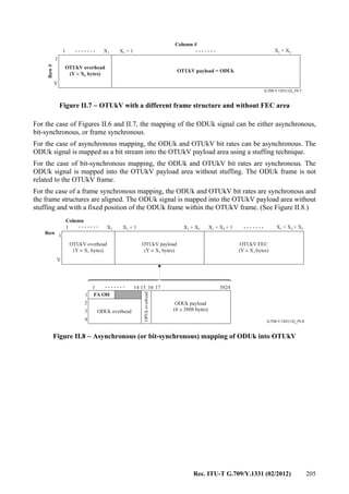
![206 Rec. ITU-T G.709/Y.1331 (02/2012)
Appendix III
Example of ODUk multiplexing
(This appendix does not form an integral part of this Recommendation.)
Figure III.1 illustrates the multiplexing of four ODU1 signals into an ODU2. The ODU1 signals
including the frame alignment overhead and an all-0s pattern in the OTUk overhead locations are
adapted to the ODU2 clock via justification (asynchronous mapping). These adapted ODU1 signals
are byte interleaved into the OPU2 payload area, and their justification control and opportunity
signals (JC, NJO) are frame interleaved into the OPU2 overhead area.
ODU2 overhead is added after which the ODU2 is mapped into the OTU2 [or OTU2V]. OTU2
[or OTU2V] overhead and frame alignment overhead are added to complete the signal for transport
via an OTM signal.
Alignment
Alignment
Alignment
Alignment
Alignment
Alignment
Alignment
OPU1OH
Client layer signal
(e.g., STM-16, ATM, GFP)
ODU1 OH
Alignment
OPU1OH
Client layer signal
(e.g., STM-16, ATM, GFP)
ODU1 OH
G.709-Y.1331(12)_FIII.1
Alignment
Alignment
OPU1OH
OPU2OH
OPU2OH
ODU1
ODU2
OTU2
OTU2 OH
OTU2 FEC
Client layer signal
(e.g., STM-16, ATM, GFP)
ODU1 OH
ODU2 OH
ODU2 OH
4×
NOTE – The ODU1 floats in a quarter of the OPU2 payload area. An ODU1 frame will cross multiple ODU2 frame boundaries. A
complete ODU1 frame (15296 bytes) requires the bandwidth of (15296/3808) 4.017 ODU2 frames. This is not illustrated.
Figure III.1 – Example of multiplexing 4 ODU1 signals into an ODU2
Figure III.2 illustrates the multiplexing of two ODU0 signals into an ODU1. The ODU0 signals
including the frame alignment overhead and an all-0s pattern in the OTUk overhead locations are
adapted to the ODU1 clock via justification (asynchronous mapping). These adapted ODU0 signals
are byte interleaved into the OPU1 payload area, and their justification control and opportunity
signals (JC, NJO) are frame interleaved into the OPU1 overhead area and ODU1 overhead is added.](https://image.slidesharecdn.com/dd175b1f-a76f-4140-ae81-1f3e866587da-160607171351/85/T-REC-G-709-201202-I-PDF-E-214-320.jpg)
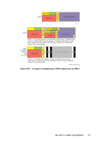
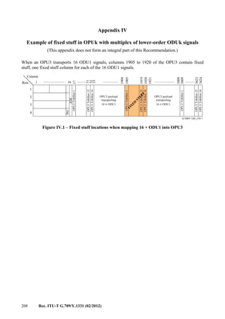
![Rec. ITU-T G.709/Y.1331 (02/2012) 209
Appendix V
ODUk multiplex structure identifier (MSI) examples
(This appendix does not form an integral part of this Recommendation.)
The following figures present four examples of ODU1 and ODU2 carriage within an OPU3 and the
associated MSI encoding.
1 2 3 4 5 6 7 8
PSI[2] 00 000000 TS1
PSI[3] 00 000001 TS2
PSI[4] 00 000010 TS3
PSI[5] 00 000011 TS4
PSI[6] 00 000100 TS5
PSI[7] 00 000101 TS6
PSI[8] 00 000110 TS7
PSI[9] 00 000111 TS8
PSI[10] 00 001000 TS9
PSI[11] 00 001001 TS10
PSI[12] 00 001010 TS11
PSI[13] 00 001011 TS12
PSI[14] 00 001100 TS13
PSI[15] 00 001101 TS14
PSI[16] 00 001110 TS15
PSI[17] 00 001111 TS16
Figure V.1 – OPU3-MSI coding for the case of 16 ODU1s into OPU3
1 2 3 4 5 6 7 8
PSI[2] 01 000000 TS1
PSI[3] 01 000001 TS2
PSI[4] 01 000010 TS3
PSI[5] 01 000011 TS4
PSI[6] 01 000000 TS5
PSI[7] 01 000001 TS6
PSI[8] 01 000010 TS7
PSI[9] 01 000011 TS8
PSI[10] 01 000000 TS9
PSI[11] 01 000001 TS10
PSI[12] 01 000010 TS11
PSI[13] 01 000011 TS12
PSI[14] 01 000000 TS13
PSI[15] 01 000001 TS14
PSI[16] 01 000010 TS15
PSI[17] 01 000011 TS16
Figure V.2 – OPU3-MSI coding for the case of 4 ODU2s into OPU3 TS# (1, 5, 9, 13),
(2, 6, 10, 14), (3, 7, 11, 15) and (4, 8, 12, 16)](https://image.slidesharecdn.com/dd175b1f-a76f-4140-ae81-1f3e866587da-160607171351/85/T-REC-G-709-201202-I-PDF-E-217-320.jpg)
![210 Rec. ITU-T G.709/Y.1331 (02/2012)
1 2 3 4 5 6 7 8
PSI[2] 01 000000 TS1
PSI[3] 01 000001 TS2
PSI[4] 01 000001 TS3
PSI[5] 01 000010 TS4
PSI[6] 01 000000 TS5
PSI[7] 01 000011 TS6
PSI[8] 01 000011 TS7
PSI[9] 01 000011 TS8
PSI[10] 01 000000 TS9
PSI[11] 01 000000 TS10
PSI[12] 01 000001 TS11
PSI[13] 01 000001 TS12
PSI[14] 01 000011 TS13
PSI[15] 01 000010 TS14
PSI[16] 01 000010 TS15
PSI[17] 01 000010 TS16
Figure V.3 – OPU3-MSI coding for the case of 4 ODU2s into OPU3 TS# (1, 5, 9, 10),
(2, 3, 11, 12), (4, 14, 15, 16) and (6, 7, 8, 13)
1 2 3 4 5 6 7 8
PSI[2] 01 000000 TS1
PSI[3] 00 000001 TS2
PSI[4] 00 000010 TS3
PSI[5] 01 000001 TS4
PSI[6] 01 000000 TS5
PSI[7] 00 000101 TS6
PSI[8] 00 000110 TS7
PSI[9] 01 000001 TS8
PSI[10] 01 000000 TS9
PSI[11] 01 000001 TS10
PSI[12] 00 001010 TS11
PSI[13] 00 001011 TS12
PSI[14] 01 000000 TS13
PSI[15] 00 001101 TS14
PSI[16] 00 001110 TS15
PSI[17] 01 000001 TS16
Figure V.4 – OPU3-MSI coding for the case of 5 ODU1s and 2 ODU2s
into OPU3 TS# (2), (6), (11), (12), (14), (1, 5, 9, 13) and (4, 8, 10, 16)
and OPU3 TS# 3, 7, 15 unallocated (default to ODU1)](https://image.slidesharecdn.com/dd175b1f-a76f-4140-ae81-1f3e866587da-160607171351/85/T-REC-G-709-201202-I-PDF-E-218-320.jpg)
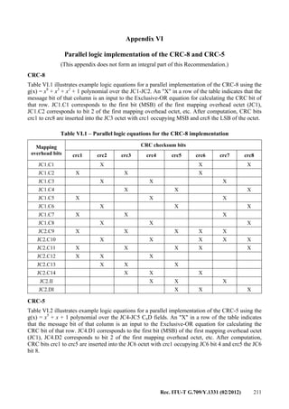
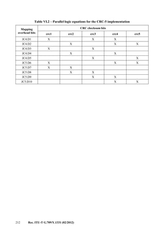
![Rec. ITU-T G.709/Y.1331 (02/2012) 213
Appendix VII
OTL4.10 structure
(This appendix does not form an integral part of this Recommendation.)
The purpose of the OTM-0.4v4 interface, as defined in clause 8.1.3, is to enable the re-use of
modules developed for Ethernet 100GBASE-LR4 or 100GBASE-ER4 interfaces. These modules
have corresponding optical specifications for OTU4 interfaces with the optical parameters as
specified for the application codes 4I1-9D1F and 4L1-9C1F, respectively, in [ITU-T G.959.1].
These modules have a four-lane WDM interface to and from a transmit/receive pair of ITU-T G.652
optical fibres, and connect to the host board via a 10-lane electrical interface. The conversion
between 10 and 4 lanes is performed using an IEEE 802.3ba PMA sublayer as specified in
[IEEE 802.3ba] clause 83. The specification of the 10-lane electrical chip-to-module interface
(CAUI) is found in [IEEE 802.3ba] Annex 83B. The application of the OTL4.10 interface is
illustrated in Figure VII.1:
Host
Board
PMA
10:4
OTL4.10
OTL4.4
Figure VII.1 – Illustration of the application of an OTL4.10 interface
Each OTL4.10 lane carries two bit-multiplexed logical lanes of an OTU4 as described in Annex C.
The logical lane format has been chosen so that the [IEEE 802.3ba] 10:4 PMA (gearbox) will
convert the OTU4 signal between a format of 10 lanes of OTL4.10 and four lanes of OTL4.4. Each
OTL4.4 lane carries five bit-multiplexed logical lanes of an OTU4 as described in Annex C.
The bit rate of an OTL4.10 lane is indicated in Table VII.1.
Table VII.1 – OTL types and capacity
OTL type OTL nominal bit rate OTL bit-rate tolerance
OTL4.10 255/227 × 9 953 280 kbit/s ±20 ppm
NOTE – The nominal OTL4.10 rate is approximately: 11 180 997.357 kbit/s.](https://image.slidesharecdn.com/dd175b1f-a76f-4140-ae81-1f3e866587da-160607171351/85/T-REC-G-709-201202-I-PDF-E-221-320.jpg)
![214 Rec. ITU-T G.709/Y.1331 (02/2012)
Appendix VIII
CPRI into LO ODU mapping
(This appendix does not form an integral part of this Recommendation.)
CPRI constant bit rate signals (CPRI options 1 to 6) may be transported over an ODUk connection.
These CBR signals are mapped into an LO OPUk via the generic mapping procedure as specified in
clause 17.7 for CPRI options 1 to 3 and via the bit-synchronous mapping procedure as specified in
clause 17.9 for CPRI options 4 to 6.
Two CPRI signals (options 1 and 2) are transported via OPU0, one CPRI signal (option 3) is
transported via OPU1 and three CPRI signals (options 4, 5 and 6) are transported via OPUflex. The
GMP Cm and Cn (n=1) values associated with the CPRI options 1 to 3 signals are presented in
Tables VIII.1 and VIII.2.
The use of the "Experimental mapping" payload type (code 0x01) is suggested.
NOTE – OTN transport of CPRI [b-CPRI] is intended for use within an administrative domain. Users of this
Recommendation should not assume that the required performance for the CPRI client is met. It is the
responsibility of the network operator to determine if the required performance can be met. The noise
generated by the OTN would have to be handled by the CPRI system in order to meet the application
requirements. This is considered as a complex task according to the current OTN specification. The OTN
network should also be designed in order to meet the applicable symmetry requirements.
Further details are provided below.
Simulation analyses were done for the transport of CPRI Option 2, Option 3, and Option 4 clients
over OTN for the following four cases:
a) CPRI Option 2 client signal → ODU0 → ODU2 → OTU2 → ODU2 → ODU0 → CPRI
Option 2 client signal
b) CPRI Option 3 client signal → ODU1 → ODU2 → OTU2 → ODU2 → ODU1 → CPRI
Option 3 client signal
c) CPRI Option 3 client signal → ODU1 → OTU1 → ODU1 → CPRI Option 3
d) CPRI Option 4 client signal → ODU2 → OTU2 → ODU2 → CPRI Option 4
In accordance with this Appendix VIII, the mappings of the CPRI Option 2 client to ODU0 and the
CPRI Option 3 client to ODU1 are via GMP. The CPRI Option 4 client is mapped to ODUflex, and
the ODUflex is mapped to ODU2 via GMP. Finally, in (a) the ODU0 is mapped to ODU2 via GMP,
and in (b) the ODU1 is mapped to ODU2 via AMP. Cases (a) and (b) have a single mapping of the
CPRI client to OTN and one level of OTN multiplexing. Cases (c) and (d) have a single mapping to
OTN and no OTN multiplexing.
Simulations were run for no use of additional phase information for the CPRI client to LO ODU
mapper (i.e., Cn with n = 8) and 1 UI of additional phase information for the CPRI client to LO
ODU mapper (i.e., Cn with n = 1). The desynchronizer bandwidth for the HO ODU to LO ODU
demappers was 300 Hz.
The simulation results indicated that, for CPRI client desynchronizer bandwidth in the range of
100-300 Hz (current OTN client desynchronizers are 300 Hz or, in a few cases, 100 Hz or 200 Hz)
RMS frequency offset ranges from approximately 113 ppb to 190 ppb for transport of CPRI
Option 2 for case (a) and 156 ppb to 317 ppb for transport of CPRI Option 3 for case (b). In
addition, for the same range of desynchronizer bandwidths, RMS frequency offset ranges from](https://image.slidesharecdn.com/dd175b1f-a76f-4140-ae81-1f3e866587da-160607171351/85/T-REC-G-709-201202-I-PDF-E-222-320.jpg)
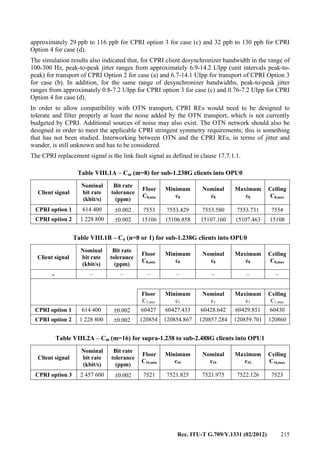
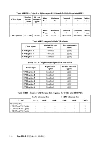
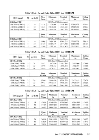
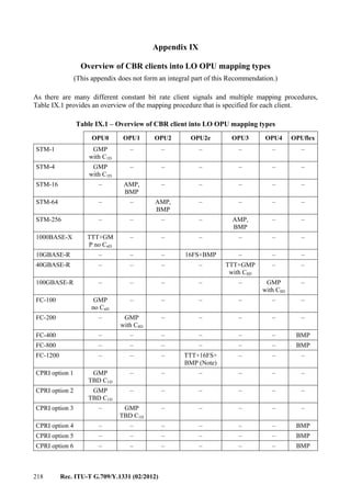
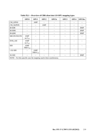
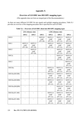
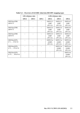
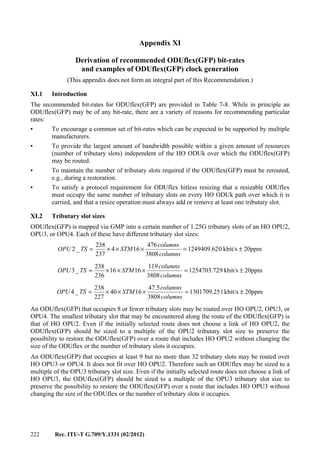
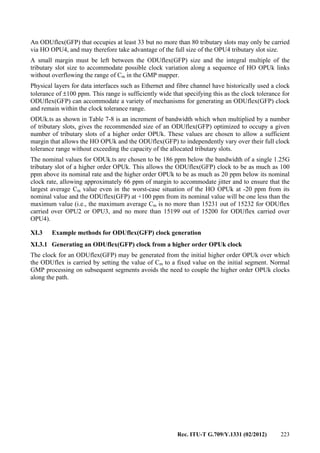
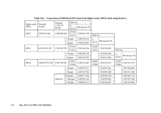
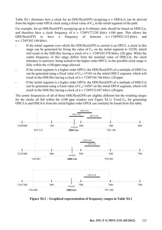
![Rec. ITU-T G.709/Y.1331 (02/2012) 227
Bibliography
[b-ITU-T G-Sup.43] ITU-T G-series Recommendations – Supplement 43 (2008),
Transport of IEEE 10GBASE-R in optical transport networks (OTN).
[b-ANSI INCITS 296] ANSI INCITS 296-1997, Information Technology – Single-Byte
Command Code Sets CONnection (SBCON) Architecture).
[b-ANSI INCITS 364] ANSI INCITS 364-2003, Information Technology – Fibre Channel
10 Gigabit (10GFC).
[b-IB ARCH] InfiniBand Trade Association (2006), InfiniBand Architecture
Specification, Volume 2, Release 1.2.1.
[b-INCITS 470] INCITS 470:2011, Information Technology – Fibre Channel –
Framing and Signaling – 3 (FC-FS-3).
[b-CPRI] CPRI Specification V5.0 (2011-09-21) Common Public Radio
Interface (CPRI), Interface Specification.](https://image.slidesharecdn.com/dd175b1f-a76f-4140-ae81-1f3e866587da-160607171351/85/T-REC-G-709-201202-I-PDF-E-235-320.jpg)