TRASMISSION MODES, IMPAIRMENTSAND MEDIUM
LECTURE 6
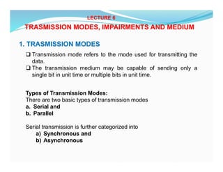
1. TRASMISSION MODES
Transmission mode refers to the mode used for transmitting the
data.
The transmission medium may be capable of sending only a
single bit in unit time or multiple bits in unit time.
Types of Transmission Modes:
There are two basic types of transmission modes
a. Serial and
b. Parallel
Serial transmission is further categorized into
a) Synchronous and
b) Asynchronous
2.
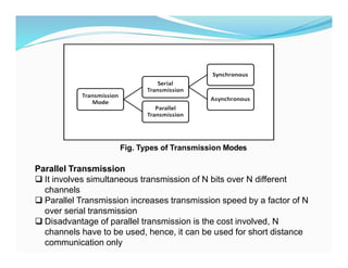
Fig. Types ofTransmission Modes
Parallel Transmission
It involves simultaneous transmission of N bits over N different
channels
Parallel Transmission increases transmission speed by a factor of N
over serial transmission
Disadvantage of parallel transmission is the cost involved, N
channels have to be used, hence, it can be used for short distance
communication only
3.
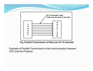
Fig. Parallel Transmissionof Data over N = 8 channels
Example of Parallel Transmission is the communication between
CPU and the Projector.
4.
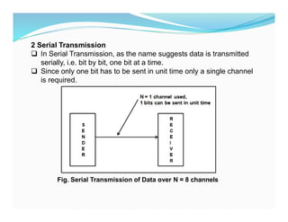
2 Serial Transmission
In Serial Transmission, as the name suggests data is transmitted
serially, i.e. bit by bit, one bit at a time.
Since only one bit has to be sent in unit time only a single channel
is required.
Fig. Serial Transmission of Data over N = 8 channels
5.
Types of SerialTransmission:
Depending upon the timing of transmission of data there are two types
of serial transmission as described below
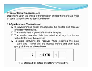
1 ASynchronous Transmission
In asynchronous serial transmission the sender and receiver
are not synchronized.
The data is sent in group of 8 bits i.e. in bytes.
The sender can start data transmission at any time instant
without informing the receiver.
To avoid confusing the receiver while receiving the data,
―start and ―stop bits are inserted before and after every
group of 8 bits as shown below
0 1 BYTE 1
Fig: Start and Bit before and after every data byte
6.
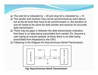
The startbit is indicated by ―0 and stop bit is indicated by ―1 .
The sender and receiver may not be synchronized as seen above
but at the bit level they have to be synchronized i.e. the duration of
one bit needs to be same for both sender and receiver for accurate
data transmission.
There may be gaps in between the data transmission indication
that there is no data being transmitted from sender. Ex. Assume a
user typing at uneven speeds, at times there is no data being
transmitted from Keyboard to the CPU.
Following is the Diagram for Asynchronous Serial Transmission.
Fig: Asynchronous Serial Transmission
7.
Advantages
1. Cheap andEffective implementation
2. Can be used for low speed communication
Disadvantages
1. Insertion of start bits, stop bits and gaps make asynchronous
transmission slow.
Application Keyboard
8.
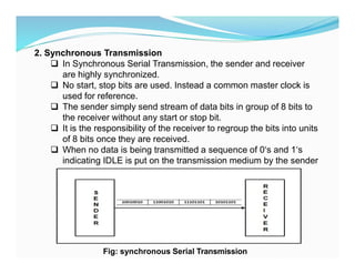
2. Synchronous Transmission
In Synchronous Serial Transmission, the sender and receiver
are highly synchronized.
No start, stop bits are used. Instead a common master clock is
used for reference.
The sender simply send stream of data bits in group of 8 bits to
the receiver without any start or stop bit.
It is the responsibility of the receiver to regroup the bits into units
of 8 bits once they are received.
When no data is being transmitted a sequence of 0‘s and 1‘s
indicating IDLE is put on the transmission medium by the sender
Fig: synchronous Serial Transmission
9.
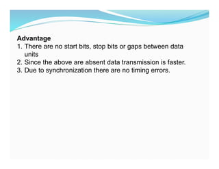
Advantage
1. There areno start bits, stop bits or gaps between data
units
2. Since the above are absent data transmission is faster.
3. Due to synchronization there are no timing errors.
10.
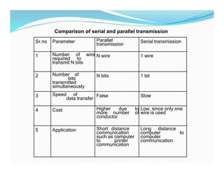
Sr.no Parameter Parallel
transmission
Serialtransmission
1 Number of wire
required to
transmit N bits
N wire 1 wire
2 Number of
bits
transmitted
simultaneously
N bits 1 bit
3 Speed of
data transfer
False Slow
4 Cost Higher due to
more number of
conductor
Low, since only one
wire is used
5 Application Short distance
communication
such as computer
to printer
communication
Long distance
computer to
computer
communication.
Comparison of serial and parallel transmission
11.
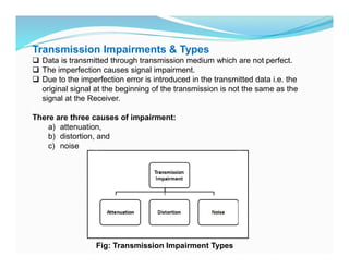
Transmission Impairments &Types
Data is transmitted through transmission medium which are not perfect.
The imperfection causes signal impairment.
Due to the imperfection error is introduced in the transmitted data i.e. the
original signal at the beginning of the transmission is not the same as the
signal at the Receiver.
There are three causes of impairment:
a) attenuation,
b) distortion, and
c) noise
Fig: Transmission Impairment Types
12.
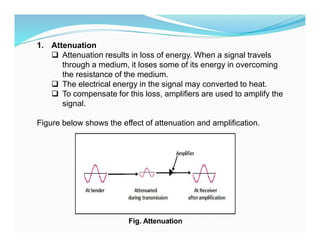
1. Attenuation
Attenuationresults in loss of energy. When a signal travels
through a medium, it loses some of its energy in overcoming
the resistance of the medium.
The electrical energy in the signal may converted to heat.
To compensate for this loss, amplifiers are used to amplify the
signal.
Figure below shows the effect of attenuation and amplification.
Fig. Attenuation
13.
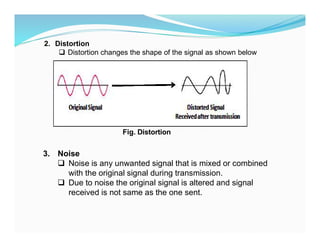
2. Distortion
Distortionchanges the shape of the signal as shown below
Fig. Distortion
3. Noise
Noise is any unwanted signal that is mixed or combined
with the original signal during transmission.
Due to noise the original signal is altered and signal
received is not same as the one sent.
14.
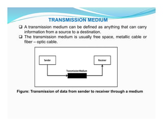
TRANSMISSION MEDIUM
Atransmission medium can be defined as anything that can carry
information from a source to a destination.
The transmission medium is usually free space, metallic cable or
fiber – optic cable.
Figure: Transmission of data from sender to receiver through a medium
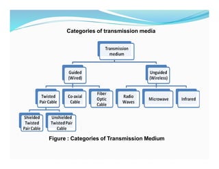
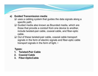
a) Guided Transmissionmedia
uses a cabling system that guides the data signals along a
specific path.
Guided media also known as Bounded media, which are
those that provide a conduit from one device to another,
include twisted-pair cable, coaxial cable, and fiber-optic
cable.
Out of these twisted-pair cable, coaxial cable transport
signals in the form of electric signals and fiber-optic cable
transport signals in the form of light. •
Types:
1. Twisted-Pair Cable
2. Coaxial Cable
3. Fiber-OpticCable
17.
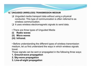
b) UNGUIDED (WIRELESS)TRANSMISSION MEDIUM
Unguided media transport data without using a physical
conductor. This type of communication is often referred to as
wireless communication.
It uses wireless electromagnetic signals to send data.
• There are three types of Unguided Media
(i) Radio waves
(ii) Micro waves
(iii) Infrared.
• Before understanding the different types of wireless transmission
medium, let us first understand the ways in which wireless signals
travel.
These signals can be sent or propagated in the following three ways:
1. Ground-wave propagation
2. Sky-wave propagation
3. Line-of-sight propagation
18.
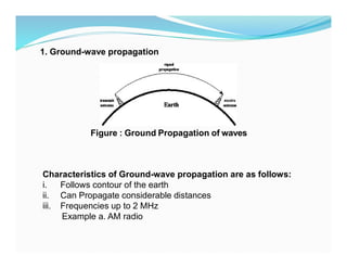
1. Ground-wave propagation
Figure: Ground Propagation of waves
Characteristics of Ground-wave propagation are as follows:
i. Follows contour of the earth
ii. Can Propagate considerable distances
iii. Frequencies up to 2 MHz
Example a. AM radio
19.
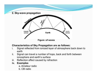
2. Sky-wave propagation
Figure:of waves
Characteristics of Sky Propagation are as follows:
i. Signal reflected from ionized layer of atmosphere back down to
earth
ii. Signal can travel a number of hops, back and forth between
ionosphere and earth‘s surface
iii. Reflection effect caused by refraction
iv. Examples
a. Amateur radio
b. CB radio
20.
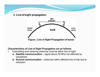
3. Line-of-sight propagation
Figure: Line of Sight Propagation of waves
Characteristics of Line of Sight Propagation are as follows:
i. Transmitting and receiving antennas must be within line of sight
a. Satellite communication – signal above 30 MHz not reflected by
ionosphere
b. Ground communication – antennas within effective line of site due to
refraction
21.
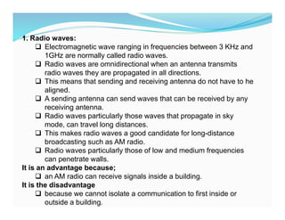
1. Radio waves:
Electromagnetic wave ranging in frequencies between 3 KHz and
1GHz are normally called radio waves.
Radio waves are omnidirectional when an antenna transmits
radio waves they are propagated in all directions.
This means that sending and receiving antenna do not have to he
aligned.
A sending antenna can send waves that can be received by any
receiving antenna.
Radio waves particularly those waves that propagate in sky
mode, can travel long distances.
This makes radio waves a good candidate for long-distance
broadcasting such as AM radio.
Radio waves particularly those of low and medium frequencies
can penetrate walls.
It is an advantage because;
an AM radio can receive signals inside a building.
It is the disadvantage
because we cannot isolate a communication to first inside or
outside a building.
22.
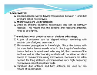
2. Microwaves:
Electromagneticwaves having frequencies between 1 and 300
GHz are called microwaves.
Microwaves are unidirectional;
when an antenna transmits microwaves they can be narrowly
focused. This means that the sending and receiving antennas
need to be aligned.
The unidirectional property has an obvious advantage.
A pair of antennas can be aligned without interfering with
another pair of aligned antennas. •
Microwaves propagation is line-of-sight. Since the towers with
the mounted antennas needs to be in direct sight of each other,
towers that are far apart need to be very tall, the curvature of the
earth as well as other blocking obstacles do not allow two short
towers to communicate using microwaves, Repeaters are often
needed for long distance communication very high frequency
microwaves cannot penetrate walls.
Parabolic dish antenna and horn antenna are used for this
means of transmission
23.
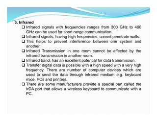
3. Infrared
Infraredsignals with frequencies ranges from 300 GHz to 400
GHz can be used for short range communication.
Infrared signals, having high frequencies, cannot penetrate walls.
This helps to prevent interference between one system and
another.
Infrared Transmission in one room cannot be affected by the
infrared transmission in another room.
Infrared band, has an excellent potential for data transmission.
Transfer digital data is possible with a high speed with a very high
frequency. There are number of computer devices which are
used to send the data through infrared medium e.g. keyboard
mice, PCs and printers.
There are some manufacturers provide a special part called the
IrDA port that allows a wireless keyboard to communicate with a
PC.
24.
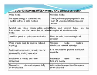
COMPARISON BETWEEN WIREDAND WIRELESS MEDIA
Wired media Wireless media
The signal energy is contained and
guided within a solid medium
The signal energy propagates in the
form of unguided electromagnetic
waves.
Twisted pair wires, coaxial cable, optical
fiber cables are the examples of wired
media.
Radio and infrared lights are the
examples of wireless media.
Used for point to point communication Used for radio broadcasting in all
direction
Wired media lead to discrete network
topology
Wireless media leads to
continuous network topology
Additional transmission capacity can be
procured by adding more wire
It is not possible procure additional
capacity.
Installation is costly and time
consuming
Installation needs less
time and money
Attenuation depends exponentially
on the distance
Attenuation is proportional to square
of the distance.
25.
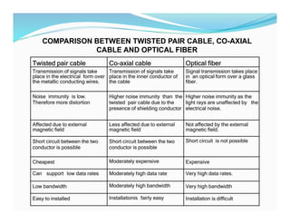
COMPARISON BETWEEN TWISTEDPAIR CABLE, CO-AXIAL
CABLE AND OPTICAL FIBER
Twisted pair cable Co-axial cable Optical fiber
Transmission of signals take
place in the electrical form over
the metallic conducting wires.
Transmission of signals take
place in the inner conductor of
the cable
Signal transmission takes place
in an optical form over a glass
fiber.
Noise immunity is low.
Therefore more distortion
Higher noise immunity than the
twisted pair cable due to the
presence of shielding conductor
Higher noise immunity as the
light rays are unaffected by the
electrical noise.
Affected due to external
magnetic field
Less affected due to external
magnetic field
Not affected by the external
magnetic field.
Short circuit between the two
conductor is possible
Short circuit between the two
conductor is possible
Short circuit is not possible
Cheapest Moderately expensive Expensive
Can support low data rates Moderately high data rate Very high data rates.
Low bandwidth Moderately high bandwidth Very high bandwidth
Easy to installed Installationis fairly easy Installation is difficult
26.
2. Explain Paralleltransmission mode
3. Explain Serial transmission mode and list its types
4. Explain Asynchronous serial transmission
5. Explain Synchronous Serial Transmission
6. Write a short note on transmission impairments
ASSIGNMENTS
7. Write short notes on :
a) Radio waves
b) Microwaves
c) Infrared


![Chapter-2 Communiction media [Autosaved].ppt](https://cdn.slidesharecdn.com/ss_thumbnails/chapter-2communictionmediaautosaved-260117143116-9787c933-thumbnail.jpg?width=640&height=640&fit=bounds)


