NETWORKING DEVICES ANDCABLING
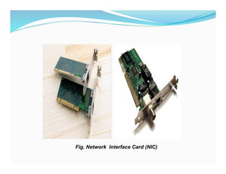
1. Network Interface Card(NIC)
-A network interface card (NIC) is a hardware component,
typically a circuit board or chip, installed on a computer so it
can connect to a network.
Functions Modern NICs
-NIC provides the link between your computer and your
network. It provides the physical connection between the
network and the workstation
-NIC provides the physical connection between machine and
medium. It controls the host’s access to the medium
-NIC translates the parallel signals produced by the computer
into serial format that is sent over the network
LECTURE 4
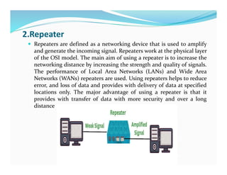
2.Repeater
Repeaters aredefined as a networking device that is used to amplify
and generate the incoming signal. Repeaters work at the physical layer
of the OSI model. The main aim of using a repeater is to increase the
networking distance by increasing the strength and quality of signals.
The performance of Local Area Networks (LANs) and Wide Area
Networks (WANs) repeaters are used. Using repeaters helps to reduce
error, and loss of data and provides with delivery of data at specified
locations only. The major advantage of using a repeater is that it
provides with transfer of data with more security and over a long
distance
4.
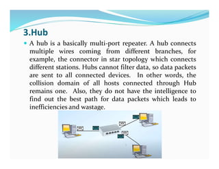
3.Hub
A hubis a basically multi-port repeater. A hub connects
multiple wires coming from different branches, for
example, the connector in star topology which connects
different stations. Hubs cannot filter data, so data packets
are sent to all connected devices. In other words, the
collision domain of all hosts connected through Hub
remains one. Also, they do not have the intelligence to
find out the best path for data packets which leads to
inefficiencies and wastage.
5.
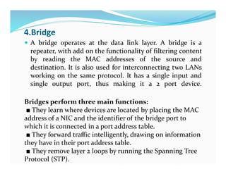
4.Bridge
A bridgeoperates at the data link layer. A bridge is a
repeater, with add on the functionality of filtering content
by reading the MAC addresses of the source and
destination. It is also used for interconnecting two LANs
working on the same protocol. It has a single input and
single output port, thus making it a 2 port device.
Bridges perform three main functions:
■ They learn where devices are located by placing the MAC
address of a NIC and the identifier of the bridge port to
which it is connected in a port address table.
■ They forward traffic intelligently, drawing on information
they have in their port address table.
■ They remove layer 2 loops by running the Spanning Tree
Protocol (STP).
6.
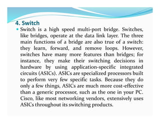
4. Switch
Switchis a high speed multi-port bridge. Switches,
like bridges, operate at the data link layer. The three
main functions of a bridge are also true of a switch:
they learn, forward, and remove loops. However,
switches have many more features than bridges; for
instance, they make their switching decisions in
hardware by using application-specific integrated
circuits (ASICs). ASICs are specialized processors built
to perform very few specific tasks. Because they do
only a few things, ASICs are much more cost-effective
than a generic processor, such as the one in your PC.
Cisco, like most networking vendors, extensively uses
ASICs throughout its switching products.
7.
5.Router
A routeris a device like a switch that routes data packets
based on their IP addresses.
The router is mainly a Network Layer device.
Routers normally connect LANs and WANs and have a
dynamically updating routing table based on which they
make decisions on routing the data packets.
The router divides the broadcast domains of hosts
connected through it
6.Gateway
Gateway isa network point that acts as an entrance to another network.
Essentially a gateway is normally a computer that operates in all layers of
the OSI model
A gateway, as the name suggests, is a passage to connect two networks that
may work upon different networking models.
They work as messenger agents that take data from one system, interpret it,
and transfer it to another system.
Gateways are also called protocol converters and can operate at any
network layer.
Gateways are generally more complex than switches or routers.
A gateway is also called a protocol converter.
10.
Note..
Hubs cannotsolve bandwidth or collision problems.
Bridges and switches, on the other hand, can.
Bridges and switches take one large collision domain and
split it into a bunch of smaller ones.
In this sense, they create extra collision domains, since
each interface of the layer 2 device is a separate collision
domain. This process is called micro segmentation.
Routers, at the network layer, can also solve collision
problems, but they cost more than bridges or switches
11.
EXPERIMENT 1 PART1
Network Cable Types and Specifications
,
There are three types of network cables;
a) coaxial,
b) twisted-pair, and
c) fiber-optic
To connect two or more computers or networking devices in a network
network cables are used
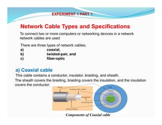
a) Coaxial cable
This cable contains a conductor, insulator, braiding, and sheath.
The sheath covers the braiding, braiding covers the insulation, and the insulation
covers the conductor.
Components of Coaxial cable
12.
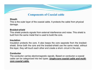
Components of Coaxialcable
Sheath
This is the outer layer of the coaxial cable. It protects the cable from physical
damage.
Braided-shield
This shield protects signals from external interference and noise. This shield is
built from the same metal that is used to build the core.
Insulation
Insulation protects the core. It also keeps the core separate from the braided-
shield. Since both the core and the braided-shield use the same metal, without
this layer, they will touch each other and create a short- circuit in the wire.
Conductor
The conductor carries electromagnetic signals. Based on conductor a coaxial
cable can be categorized into two types; single-core coaxial cable and multi-
core coaxial cable.
13.
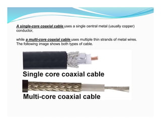
A single-core coaxialcable uses a single central metal (usually copper)
conductor,
while a multi-core coaxial cable uses multiple thin strands of metal wires.
The following image shows both types of cable.
14.
Coaxial cables incomputer networks
The coaxial cables were not primarily developed for the computer network. These
cables were developed for general purposes. They were in use even before
computer networks came into existence. They are still used even their use in
computer networks has been completely discontinued.
At the beginning of computer networking, when there were no dedicated media
cables available for computer networks, network administrators began using
coaxial cables to build computer networks.
Because of low-cost and long durability, coaxial cables were used in computer
networking for nearly two decades (80s and 90s). Coaxial cables are no longer
used to build any type of computer network.
Specifications of coaxial cables
Coaxial cables have been in use for the last four decades. During these years,
based on several factors such as the thickness of the sheath, the metal of the
conductor, and the material used in insulation, hundreds of specifications have
been created to specify the characteristics of coaxial cables.
15.
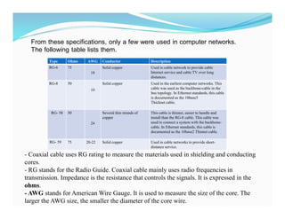
From these specifications,only a few were used in computer networks.
The following table lists them.
Type Ohms AWG Conductor Description
RG-6 75
18
Solid copper Used in cable network to provide cable
Internet service and cable TV over long
distances.
RG-8 50
10
Solid copper Used in the earliest computer networks. This
cable was used as the backbone-cable in the
bus topology. In Ethernet standards, this cable
is documented as the 10base5
Thicknet cable.
RG- 58 50
24
Several thin strands of
copper
This cable is thinner, easier to handle and
install than the RG-8 cable. This cable was
used to connect a system with the backbone-
cable. In Ethernet standards, this cable is
documented as the 10base2 Thinnet cable.
RG- 59 75 20-22 Solid copper Used in cable networks to provide short-
distance service.
- Coaxial cable uses RG rating to measure the materials used in shielding and conducting
cores.
- RG stands for the Radio Guide. Coaxial cable mainly uses radio frequencies in
transmission. Impedance is the resistance that controls the signals. It is expressed in the
ohms.
- AWG stands for American Wire Gauge. It is used to measure the size of the core. The
larger the AWG size, the smaller the diameter of the core wire.
16.
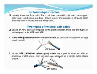
b) Twisted-pair cables
Usually, there are four pairs. Each pair has one solid color and one stripped
color wire. Solid colors are blue, brown, green and orange. In stripped color,
the solid color is mixed with the white color.
Two types of twisted-pair cable
Based on how pairs are stripped in the plastic sheath, there are two types of
twisted-pair cable; UTP and STP.
1. In the UTP (Unshielded twisted-pair) cable, all pairs are wrapped in a single
plastic sheath.
2. In the STP (Shielded twisted-pair) cable, each pair is wrapped with an
additional metal shield, then all pairs are wrapped in a single outer plastic
sheath.
17.
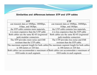
STP UTP
can transmitdata at 10Mbps, 100Mbps,
1Gbps, and 10Gbps.
can transmit data at 10Mbps, 100Mbps,
1Gbps, and 10Gbps.
the STP cable contains more materials, the UTP cable contains less materials,
it is more expensive than the UTP cable it is less expensive than the STP cable
Both cables use the same RJ-45 (registered
jack) modular connectors.
Both cables use the same RJ-45 (registered
jack) modular connectors
The STP provides more noise and EMI
resistant than the UTP cable.
The UTP provides less noise and EMI
resistant than the STP cable.
The maximum segment length for both cables
is 100 meters or 328 feet.
The maximum segment length for both cables
is 100 meters or 328 feet.
Both cables can accommodate a maximum of
1024 nodes in each segment.
Both cables can accommodate a maximum of
1024 nodes in each segment.
Similarities and differences between STP and UTP cables
18.
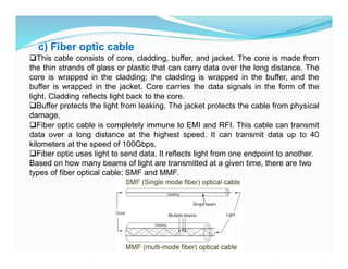
c) Fiber opticcable
This cable consists of core, cladding, buffer, and jacket. The core is made from
the thin strands of glass or plastic that can carry data over the long distance. The
core is wrapped in the cladding; the cladding is wrapped in the buffer, and the
buffer is wrapped in the jacket. Core carries the data signals in the form of the
light. Cladding reflects light back to the core.
Buffer protects the light from leaking. The jacket protects the cable from physical
damage.
Fiber optic cable is completely immune to EMI and RFI. This cable can transmit
data over a long distance at the highest speed. It can transmit data up to 40
kilometers at the speed of 100Gbps.
Fiber optic uses light to send data. It reflects light from one endpoint to another.
Based on how many beams of light are transmitted at a given time, there are two
types of fiber optical cable; SMF and MMF.
19.
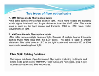
1. SMF (Single-modefiber) optical cable
•This cable carries only a single beam of light. This is more reliable and supports
much higher bandwidth and longer distances than the MMF cable. This cable
uses a laser as the light source and transmits 1300 or 1550 nano- meter
wavelengths of light.
2. MMF (multi-mode fiber) optical cable
•This cable carries multiple beams of light. Because of multiple beams, this cable
carries much more data than the SMF cable. This cable is used in shorter
distances. This cable uses an LED as the light source and transmits 850 or 1300
nano-meter wavelengths of light.
Two types of fiber optical cable
Fiber Optic Cabling Solutions
The largest solutions of pre-terminated fiber optics, including multimode and
single-mode patch cords, MTP/MPO fiber trunks and harnesses, plug-n-play
modules/cassettes and fiber enclosures.
20.
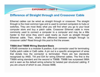
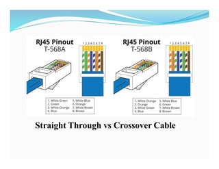
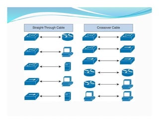
Difference of Straightthrough and Crossover Cable
Ethernet cables can be wired as straight through or crossover. The straight
through is the most common type and is used to connect computers to hubs or
switches. They are most likely what you will find when you go to your local
computer store and buy a patch cable. Crossover Ethernet cable is more
commonly used to connect a computer to a computer and may be a little
harder to find since they aren’t used nearly as much as straight through
Ethernet cable. Then, what’s the difference between straight through vs
crossover cable? Read through this post to find the answer.
T568A And T568B Wiring Standard Basis
A RJ45 connector is a modular 8 position, 8 pin connector used for terminating
Cat5e patch cable or Cat6 cable. A pin out is a specific arrangement of wires
that dictate how the connector is terminated. There are two standards
recognized by ANSI, TIA and EIA for wiring Ethernet cables. The first is the
T568A wiring standard and the second is T568B. T568B has surpassed 568A
and is seen as the default wiring scheme for twisted pair structured cabling. If
you are unsure of which to use, choose 568B.
EXPERIMENT 1 PART 2
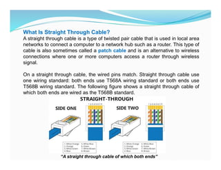
What Is StraightThrough Cable?
A straight through cable is a type of twisted pair cable that is used in local area
networks to connect a computer to a network hub such as a router. This type of
cable is also sometimes called a patch cable and is an alternative to wireless
connections where one or more computers access a router through wireless
signal.
On a straight through cable, the wired pins match. Straight through cable use
one wiring standard: both ends use T568A wiring standard or both ends use
T568B wiring standard. The following figure shows a straight through cable of
which both ends are wired as the T568B standard.
“A straight through cable of which both ends”
23.
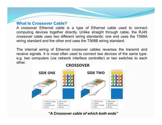
What Is CrossoverCable?
A crossover Ethernet cable is a type of Ethernet cable used to connect
computing devices together directly. Unlike straight through cable, the RJ45
crossover cable uses two different wiring standards: one end uses the T568A
wiring standard and the other end uses the T568B wiring standard.
The internal wiring of Ethernet crossover cables reverses the transmit and
receive signals. It is most often used to connect two devices of the same type:
e.g. two computers (via network interface controller) or two switches to each
other.
“A Crossover cable of which both ends”
24.
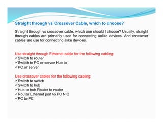
Straight through vsCrossover Cable, which to choose?
Straight through vs crossover cable, which one should I choose? Usually, straight
through cables are primarily used for connecting unlike devices. And crossover
cables are use for connecting alike devices.
Use straight through Ethernet cable for the following cabling:
Switch to router
Switch to PC or server Hub to
PC or server
Use crossover cables for the following cabling:
Switch to switch
Switch to hub
Hub to hub Router to router
Router Ethernet port to PC NIC
PC to PC
26.
Conclusion on StraightThrough vs Crossover Cable
Straight through and crossover cables are wired differently from each other.
One easy way to tell what you have is to look at the order of the colored wires
inside the RJ45 connector. If the order of the wires is the same on both ends,
then you have a straight through cable. If not, then it’s most likely a crossover
cable or was wired wrong.
At present, the straight through cable is much more popular than crossover cable
and is widely used by people.
FS.COM provides a full range straight through Cat5e, Cat6, Cat6a and Cat7
Ethernet cables with many lengths and colors options.
27.
Network cable Crimpingand Testing Tools
In This part of experiment explains the most common twisted-pair network cable
testing and crimping tools in detail. Learn the tools that you can use to crimp and
test twisted-pair network cables. Cables are the backbone of a wired network.
The stability, reliability, and performance of a wired network depend on cables.
Installing and maintaining cables in a wired network is a difficult task. To make
this task easier, a variety of network cable crimping and testing tools are
available. In this tutorial, we will not only discuss some of the most common
network cable crimping and testing tools but also understand their features and
functions.
Twisted-pair (STP and UTP) network cable crimping tools
Crimping tools are used for the following purposes.
1.To cut the network cable of the required length from the bundle.
2.To remove the outer and inner jackets of the network cable.
3.To attach the connectors on both ends of the cable.
EXPERIMENT 1 PART 3
28.
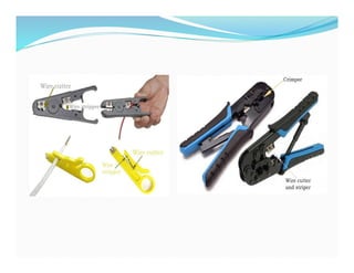
Some crimpingtools provide all the functionality while others provide one
or two functionalities.
The most common twisted-pair network cable crimping tools are
described below.
Wire Cutter: - To cut the network cable of the required length from the
bundle, you can use any standard wire cutter tool or can use a wire cutter
tool that is specially designed for the twisted-pair cable. A twisted-pair
wire cutter usually includes additional blades for stripping the wire.
Wire Stripper: - This tool is used to remove the outer and inner jackets of
the network cable. Typically, you do not
need to purchase this tool separately as all standard twisted-pair wire
cutters are equipped with wire-strippers.
Crimp tool: - This tool is used to attach the connectors to the cable.
Typically, this tool also includes a wire-cutter and wire-stripper. So if you
buy a crimp tool, you don't have to buy a wire-cutter and wire-striper
separately.
30.
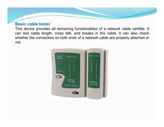
Basic cable tester
Thisdevice provides all remaining functionalities of a network cable certifier. It
can test cable length, cross talk, and breaks in the cable. It can also check
whether the connectors on both ends of a network cable are properly attached or
not.
31.
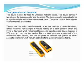
Tone generator andthe probe
This device is used to trace the unlabeled network cables. This device comes in
two pieces: the tone generator and the probe. The tone generator generates tones
or signals and places them on the network cable. The probe detects these signals
on the other end of the cable.
You can use this tool to identify network cables that run from a central location to
remote locations. For example, if you are working on a patch-panel or switch and
trying to figure out which network cable connects back to an end-device (such as a
PC), then you can use this device. Place a tone generator at one end of the
connection (end- device), and use the probe on another side (switch or patch-
panel) to determine which network cable the tone generator is connected to.