analogue and digital signals for networking module.pdf
1.
ANALOG AND DIGITALSIGNAL
LECTURE 9
To be transmitted, data must be transformed to electromagnetic
signals. Data can be Analog or Digital.
1. Analog data refers to information that is continuous;
ex. sounds made by a human voice
2. Digital data refers to information that has discrete states. Digital
data take on discrete values.
example, data are stored in computer memory in the form of Os
and 1s.
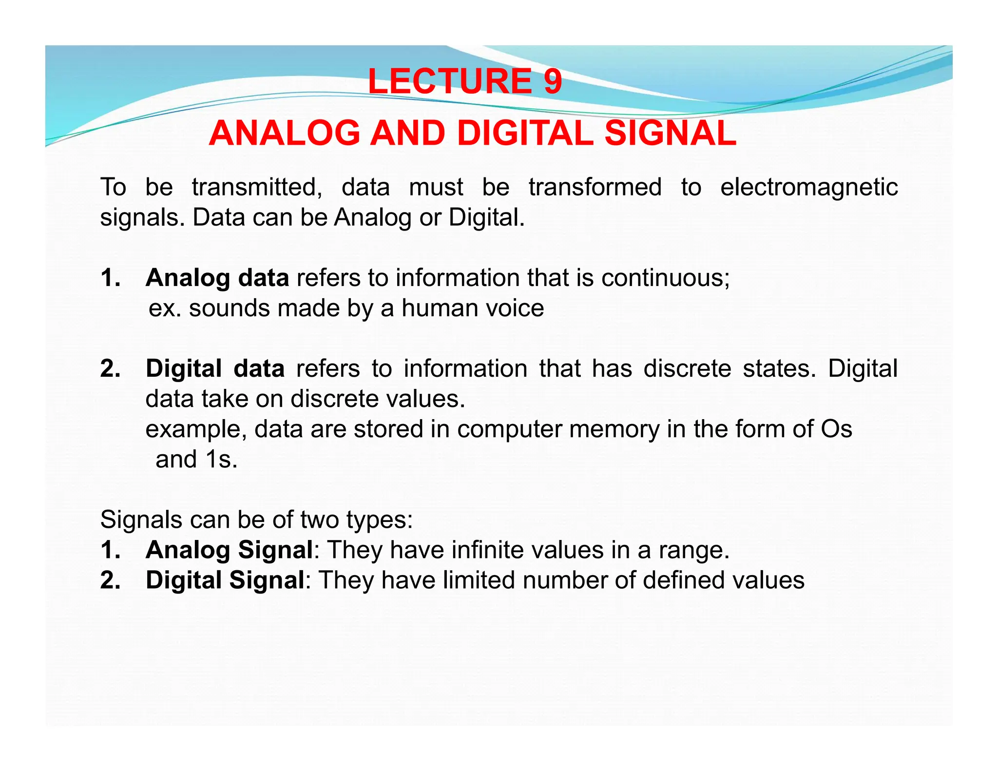
Signals can be of two types:
1. Analog Signal: They have infinite values in a range.
2. Digital Signal: They have limited number of defined values
2.
Figure: a. AnalogSignal b. Digital Signal
A. Periodic & Non Periodic Signals
Signals which repeat itself after a fixed time period are called Periodic
Signals.
Signals which do not repeat itself after a fixed time period are called
Non-Periodic Signals.
In data communications, we commonly use periodic analog signals and
non-periodic digital signals.
3.
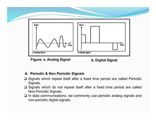
3 ANALOG SIGNAL
An analog signal has infinitely many levels of intensity over a period of
time.
As the wave moves from value A to value B, it passes through and
includes an infinite number of values along its path as it can be seen in the
figure below.
A simple analog signal is a sine wave that cannot be further decomposed
into simpler signals.
Fig. Sine wave
4.
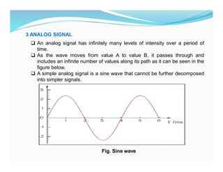
A sine waveis characterized by three parameters:
1. Peak Amplitude
2. Frequency
3. Phase
Characteristics of an Analog Signal
1. Peak Amplitude
The amplitude of a signal is the absolute value of its intensity at time t
The peak amplitude of a signal is the absolute value of the highest intensity.
The amplitude of a signal is proportional to the energy carried by the signal
Fig. Amplitude of a sine wave
5.
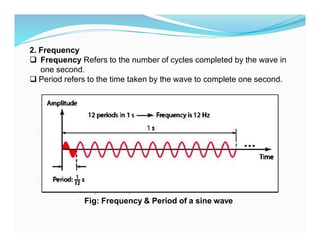
2. Frequency
FrequencyRefers to the number of cycles completed by the wave in
one second.
Period refers to the time taken by the wave to complete one second.
Fig: Frequency & Period of a sine wave
6.
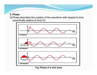
3. Phase
Phasedescribes the position of the waveform with respect to time
(specifically relative to time O).
Fig: Phase of a sine wave
7.
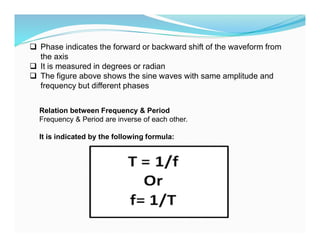
Phase indicatesthe forward or backward shift of the waveform from
the axis
It is measured in degrees or radian
The figure above shows the sine waves with same amplitude and
frequency but different phases
Relation between Frequency & Period
Frequency & Period are inverse of each other.
It is indicated by the following formula:
8.
Example1.
A wave hasa frequency of 100hz. Its period(T) is given by
T = 1/ F = 1/ 100 = 0.01 sec
Example2 .
A wave completes its one cycle in 0.25 seconds. Its frequency is given by
F = 1 / T = 1 / 0.25 = 4 Hz
4. Wavelength
The wavelength of a signal refers to the relationship between
frequency (or period) and propagation speed of the wave through a
medium.
The wavelength is the distance a signal travels in one period.
It is given by
Wavelength = Propagation Speed X Period OR
Wavelength =Propagation Speed X 1 a Frequency
It is represented by the symbol : λ (pronounced as lamda)
It is measured in micrometers
It varies from one medium to another.
9.
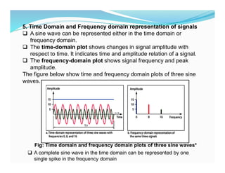
5. Time Domainand Frequency domain representation of signals
A sine wave can be represented either in the time domain or
frequency domain.
The time-domain plot shows changes in signal amplitude with
respect to time. It indicates time and amplitude relation of a signal.
The frequency-domain plot shows signal frequency and peak
amplitude.
The figure below show time and frequency domain plots of three sine
waves.
Fig: Time domain and frequency domain plots of three sine waves*
A complete sine wave in the time domain can be represented by one
single spike in the frequency domain
10.
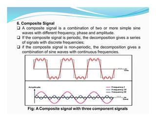
6. Composite Signal
A composite signal is a combination of two or more simple sine
waves with different frequency, phase and amplitude.
If the composite signal is periodic, the decomposition gives a series
of signals with discrete frequencies;
if the composite signal is non-periodic, the decomposition gives a
combination of sine waves with continuous frequencies.
Fig: A Composite signal with three component signals
11.
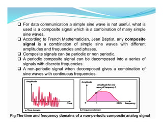
For datacommunication a simple sine wave is not useful, what is
used is a composite signal which is a combination of many simple
sine waves.
According to French Mathematician, Jean Baptist, any composite
signal is a combination of simple sine waves with different
amplitudes and frequencies and phases.
Composite signals can be periodic or non periodic.
A periodic composite signal can be decomposed into a series of
signals with discrete frequencies.
A non-periodic signal when decomposed gives a combination of
sine waves with continuous frequencies.
Fig The time and frequency domains of a non-periodic composite analog signal
12.
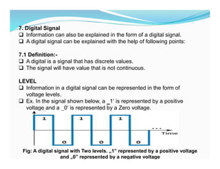
7. Digital Signal
Information can also be explained in the form of a digital signal.
A digital signal can be explained with the help of following points:
7.1 Definition:-
A digital is a signal that has discrete values.
The signal will have value that is not continuous.
LEVEL
Information in a digital signal can be represented in the form of
voltage levels.
Ex. In the signal shown below, a ‗1‘ is represented by a positive
voltage and a ‗0‘ is represented by a Zero voltage.
Fig: A digital signal with Two levels. „1‟ represented by a positive voltage
and „0‟ represented by a negative voltage
13.
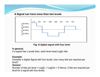
A Signal canhave more than two levels
Fig: A digital signal with four level
In general,
if a signal has L levels then, each level need Log2L bits
Example:
Consider a digital Signal with four levels, how many bits are required per
level?
Answer:
Number of bits per level = Log2L = Log2x4 = 2 Hence, 2 bits are required per
level for a signal with four levels.
14.
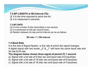
7.2 BIT LENGTHor Bit Interval (Tb)
It is the time required to send one bit.
It is measured in seconds.
7.3 BIT RATE
It is the number of bits transmitted in one second.
It is expressed as bits per second (bps).
Relation between bit rate and bit interval can be as follows
Bit rate = 1 / Bit interval
7.4 Baud Rate
It is the rate of Signal Speed, i.e the rate at which the signal changes.
A digital signal with two levels ‗0‘ & ‗1‘ will have the same baud rate and
bit rate & bit rate.
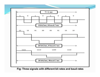
The diagram below shows three signal of period (T) 1 second
a) Signal with a bit rate of 8 bits/ sec and baud rate of 8 baud/sec
b) Signal with a bit rate of 16 bits/ sec and baud rate of 8 baud/sec
c) Signal with a bit rate of 16 bits/ sec and baud rate of 4 baud/sec
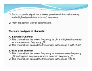
Each compositesignal has a lowest possible(minimum) frequency
and a highest possible (maximum) frequency.
From the point of view of transmission,
There are two types of channels:
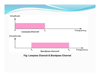
A. Low pass Channel
This channel has the lowest frequency as ‗0‘ and highest frequency
as some non-zero frequency ‗f1‘.
This channel can pass all the frequencies in the range 0 to f1. 2.5.2
B. Band pass channel
This channel has the lowest frequency as some non-zero frequency
‗f1‘ and highest frequency as some non-zero frequency ‗f2‘.
This channel can pass all the frequencies in the range f1 to f2.
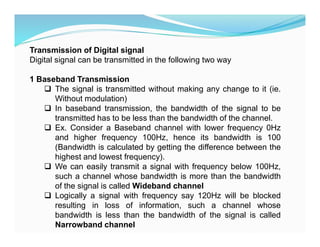
Transmission of Digitalsignal
Digital signal can be transmitted in the following two way
1 Baseband Transmission
The signal is transmitted without making any change to it (ie.
Without modulation)
In baseband transmission, the bandwidth of the signal to be
transmitted has to be less than the bandwidth of the channel.
Ex. Consider a Baseband channel with lower frequency 0Hz
and higher frequency 100Hz, hence its bandwidth is 100
(Bandwidth is calculated by getting the difference between the
highest and lowest frequency).
We can easily transmit a signal with frequency below 100Hz,
such a channel whose bandwidth is more than the bandwidth
of the signal is called Wideband channel
Logically a signal with frequency say 120Hz will be blocked
resulting in loss of information, such a channel whose
bandwidth is less than the bandwidth of the signal is called
Narrowband channel
19.
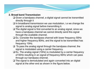
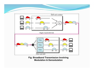
2. Broad bandTransmission
Given a bandpass channel, a digital signal cannot be transmitted
directly through it
In broadband transmission we use modulation, i.e we change the
signal to analog signal before transmitting it.
The digital signal is first converted to an analog signal, since we
have a bandpass channel we cannot directly send this signal
through the available channel.
Ex. Consider the bandpass channel with lower frequency 50Hz
and higher frequency 80Hz, and the signal to be transmitted has
frequency 10Hz.
To pass the analog signal through the bandpass channel, the
signal is modulated using a carrier frequency.
Ex. The analog signal (10Hz) is modulated by a carrier frequency
of 50Hz resulting in an signal of frequency 60Hz which can pass
through our bandpass channel.
The signal is demodulated and again converted into an digital
signal at the other end as shown in the figure below.
BANDWIDTH
Bandwidth canbe defined as the portion of the electromagnetic
spectrum occupied by the signal
It may also be defined as the frequency range over which a signal
is transmitted.
Different types of signals have different bandwidth.
Ex. Voice signal, music signal, etc
Bandwidth of analog and digital signals are calculated in separate
ways; analog signal
Bandwidth is measured in terms of its frequency (hz) but digital
signal bandwidth is measured in terms of bit rate (bits per second,
bps)
Bandwidth of signal is different from bandwidth of the
medium/channel
22.
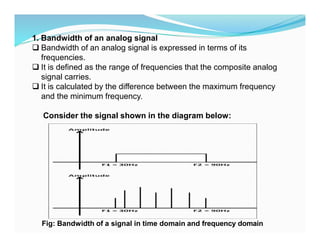
1. Bandwidth ofan analog signal
Bandwidth of an analog signal is expressed in terms of its
frequencies.
It is defined as the range of frequencies that the composite analog
signal carries.
It is calculated by the difference between the maximum frequency
and the minimum frequency.
Consider the signal shown in the diagram below:
Fig: Bandwidth of a signal in time domain and frequency domain
23.
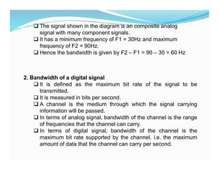
The signalshown in the diagram is an composite analog
signal with many component signals.
It has a minimum frequency of F1 = 30Hz and maximum
frequency of F2 = 90Hz.
Hence the bandwidth is given by F2 – F1 = 90 – 30 = 60 Hz
2. Bandwidth of a digital signal
It is defined as the maximum bit rate of the signal to be
transmitted.
It is measured in bits per second.
A channel is the medium through which the signal carrying
information will be passed.
In terms of analog signal, bandwidth of the channel is the range
of frequencies that the channel can carry.
In terms of digital signal, bandwidth of the channel is the
maximum bit rate supported by the channel. i.e. the maximum
amount of data that the channel can carry per second.
24.
Data rate dependson three factors:
1. The bandwidth available
2. The level of the signals we use
3. The quality of the channel (the level of noise)
The quality of the channel indicates two types:
a) A Noiseless or Perfect Channel
An ideal channel with no noise.
The Nyquist Bit rate derived by Henry Nyquist gives the bit rate
for a Noiseless Channel.
b) A Noisy Channel
A realistic channel that has some noise.
The Shannon Capacity formulated by Claude Shannon gives
the bit rate for a Noisy Channel
3. THE MAXIMUM DATA RATE OF A CHANNEL
25.
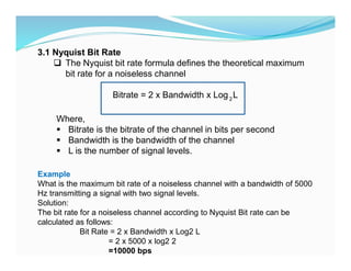
3.1 Nyquist BitRate
The Nyquist bit rate formula defines the theoretical maximum
bit rate for a noiseless channel
Bitrate = 2 x Bandwidth x Log L
2
Where,
Bitrate is the bitrate of the channel in bits per second
Bandwidth is the bandwidth of the channel
L is the number of signal levels.
Example
What is the maximum bit rate of a noiseless channel with a bandwidth of 5000
Hz transmitting a signal with two signal levels.
Solution:
The bit rate for a noiseless channel according to Nyquist Bit rate can be
calculated as follows:
Bit Rate = 2 x Bandwidth x Log2 L
= 2 x 5000 x log2 2
=10000 bps
26.
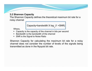
3.2 Shannon Capacity
TheShannon Capacity defines the theoretical maximum bit rate for a
noisy channel
Capacity=bandwidth X log (1 +SNR)
2
Where,
Capacity is the capacity of the channel in bits per second
Bandwidth is the bandwidth of the channel
SNR is the Signal to Noise Ratio
Shannon Capacity for calculating the maximum bit rate for a noisy
channel does not consider the number of levels of the signals being
transmitted as done in the Nyquist bit rate.
27.
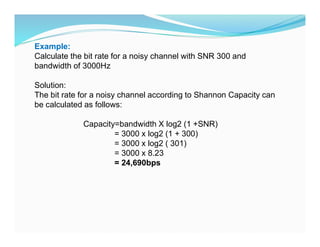
Example:
Calculate the bitrate for a noisy channel with SNR 300 and
bandwidth of 3000Hz
Solution:
The bit rate for a noisy channel according to Shannon Capacity can
be calculated as follows:
Capacity=bandwidth X log2 (1 +SNR)
= 3000 x log2 (1 + 300)
= 3000 x log2 ( 301)
= 3000 x 8.23
= 24,690bps
28.
1. Explain theterm bandwidth of a signal
2. Explain the term bandwidth of a channel.
3. Write short note on maximum data rate of a channel.
4. Explain the characteristics of an Analog signal
5. Explain the characteristics of an Digital signal
6. Explain the difference between
a) Lowpass and Bandpass channel
b) Narrowband and wideband channel
7. Explain why a digital signal requires to undergo a change before
transmitting it through a bandpass channel.
ASSIGNMENT