This document provides an overview of ITI Limited, an Indian state-owned manufacturer of telecommunications equipment. It discusses ITI's profile, facilities, products, customers, and power distribution system. Some key points include:
- ITI was established in 1948 and has six manufacturing facilities producing switching, transmission, access, and subscriber equipment.
- It produces GSM mobile equipment and supplies over nine million lines annually to domestic and export markets.
- ITI's Naini facility in Allahabad manufactures telecom transmission equipment and telephone instruments to build India's telecom infrastructure.
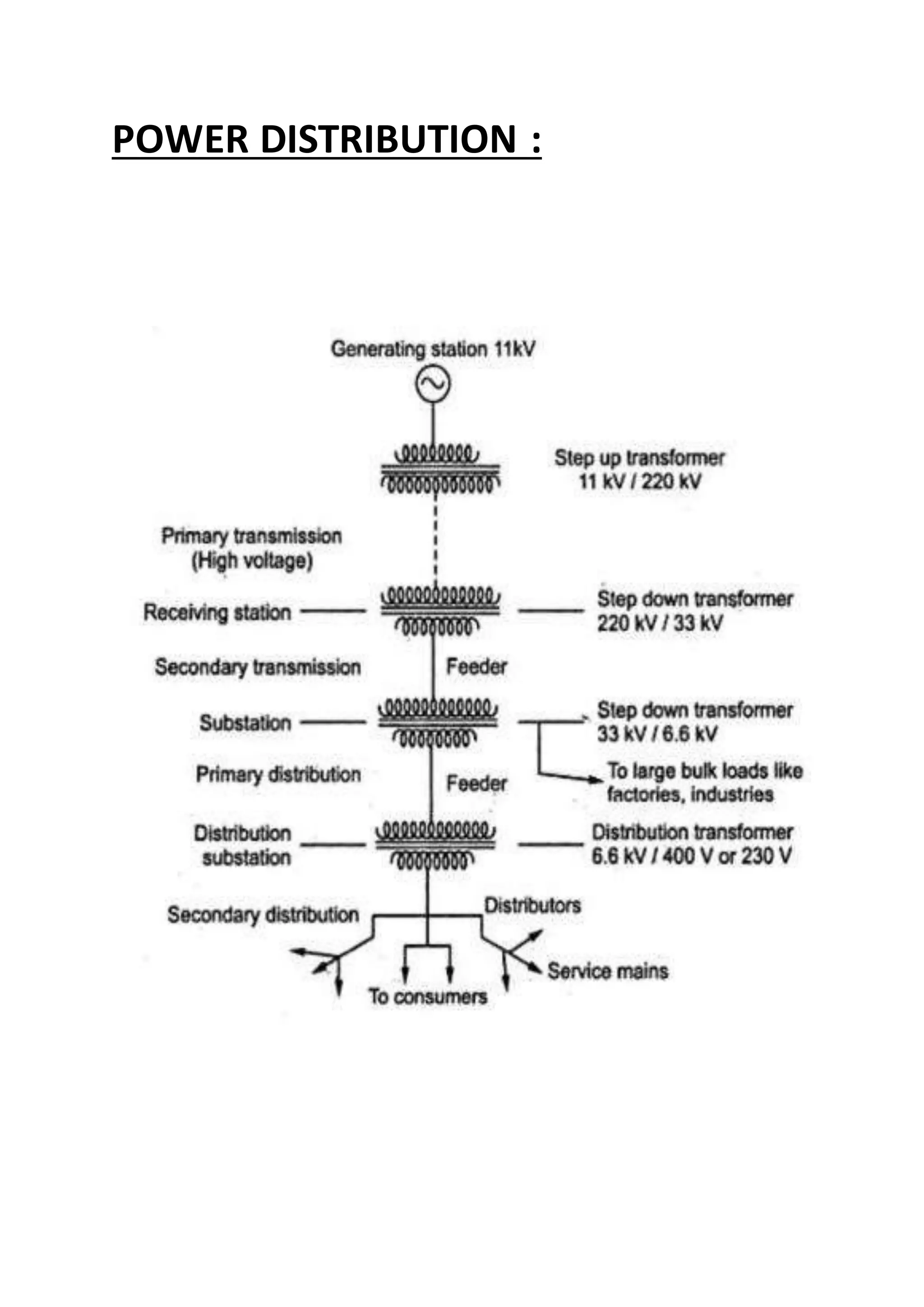
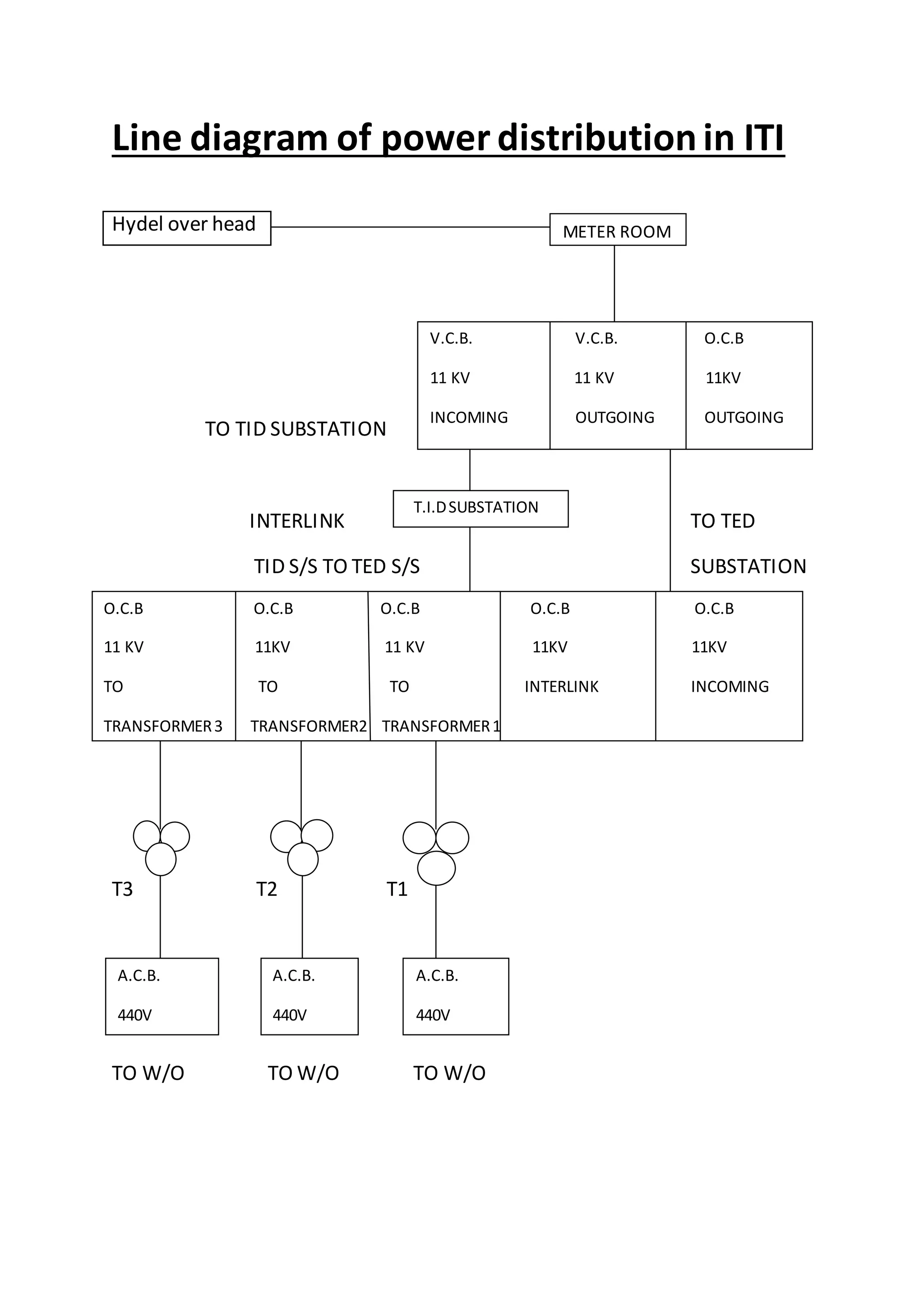
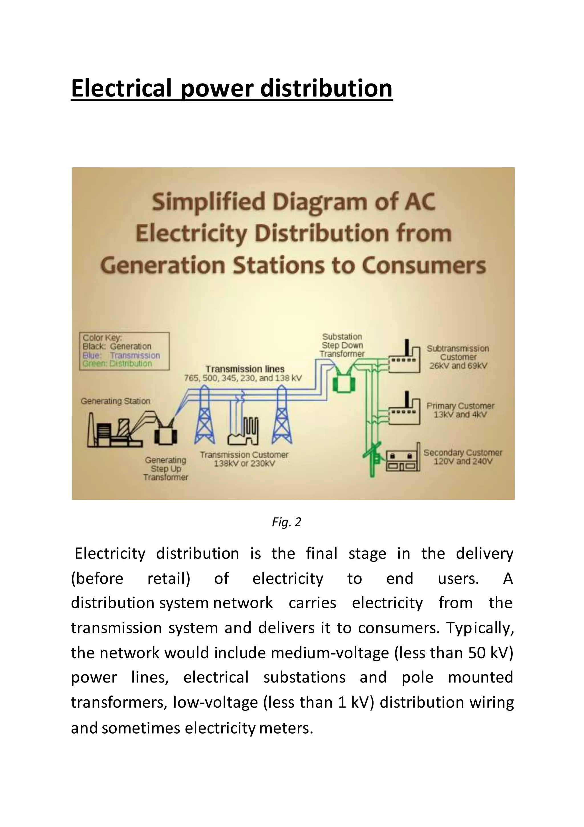
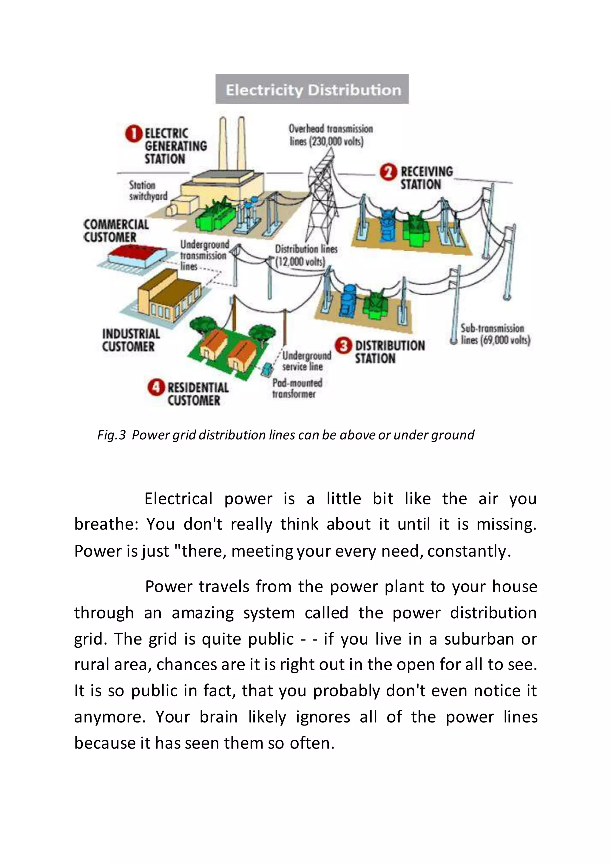
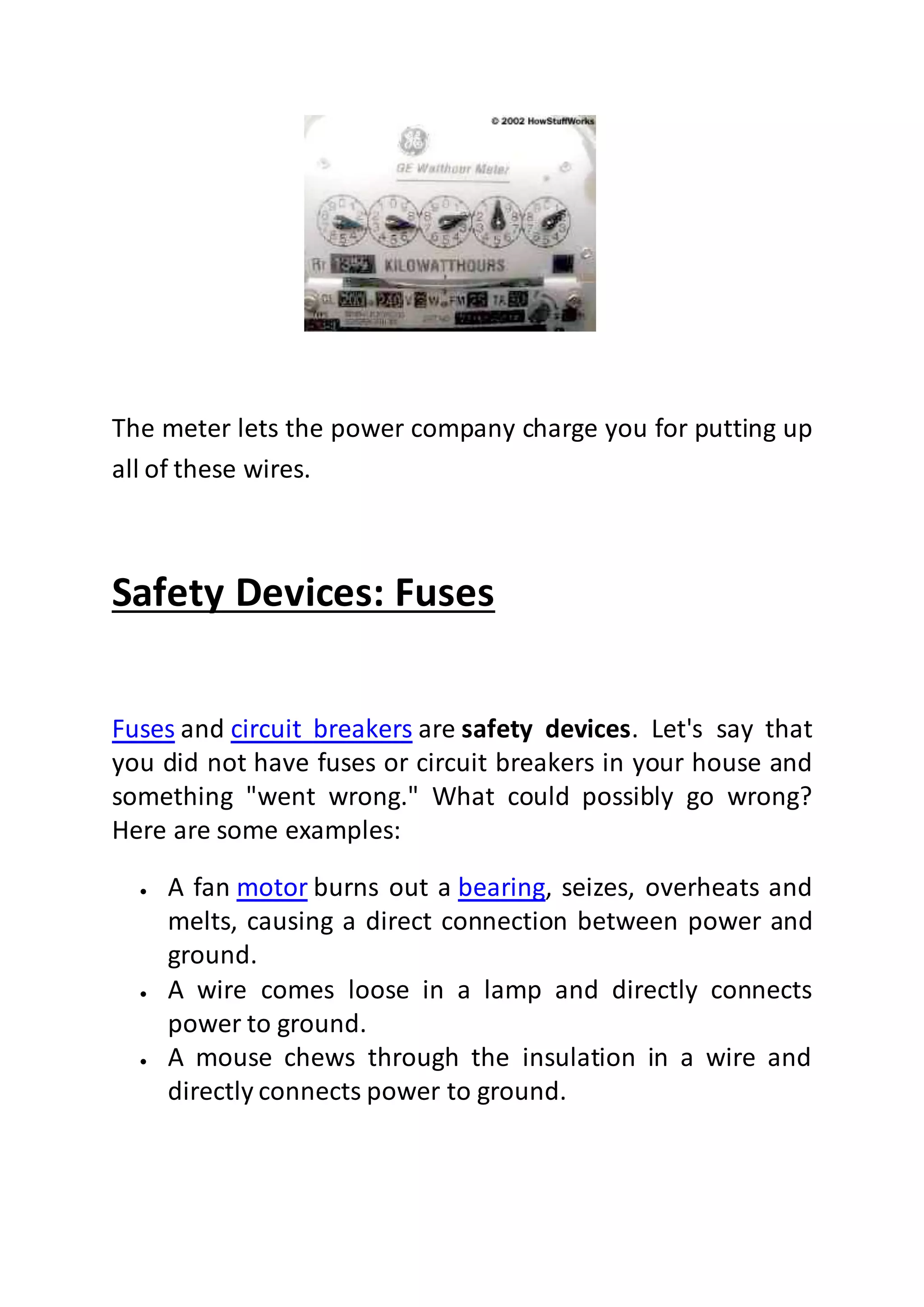
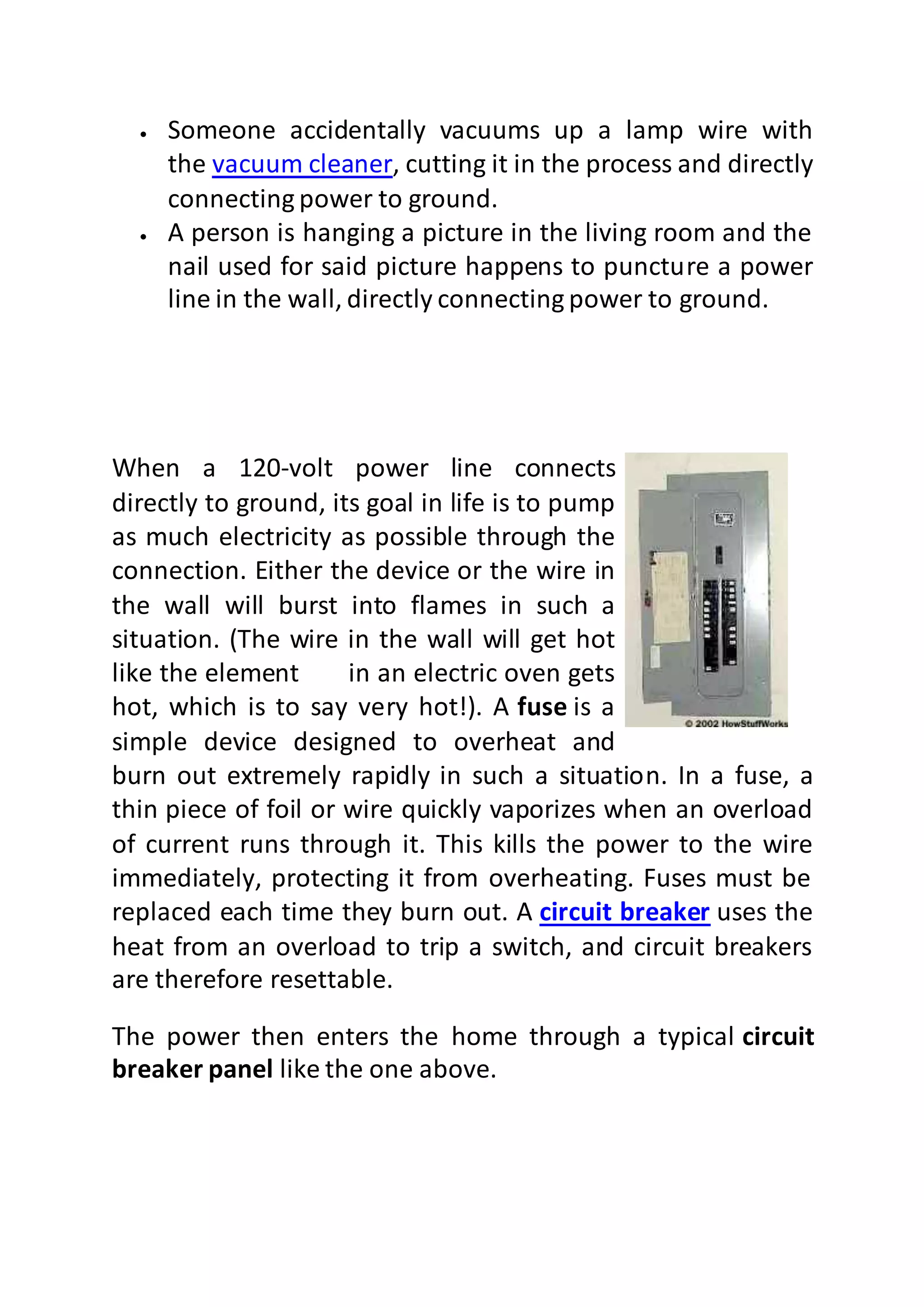
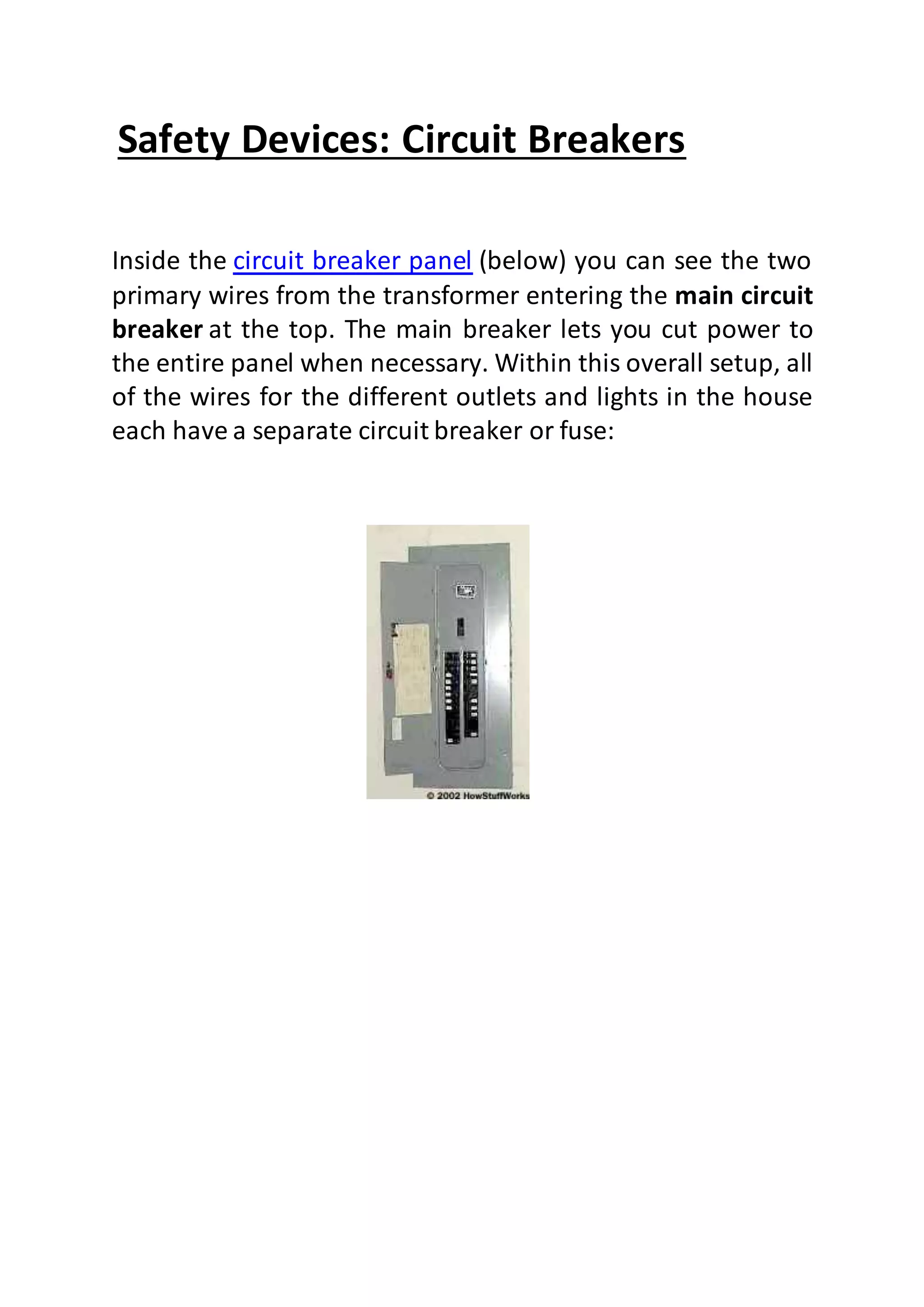
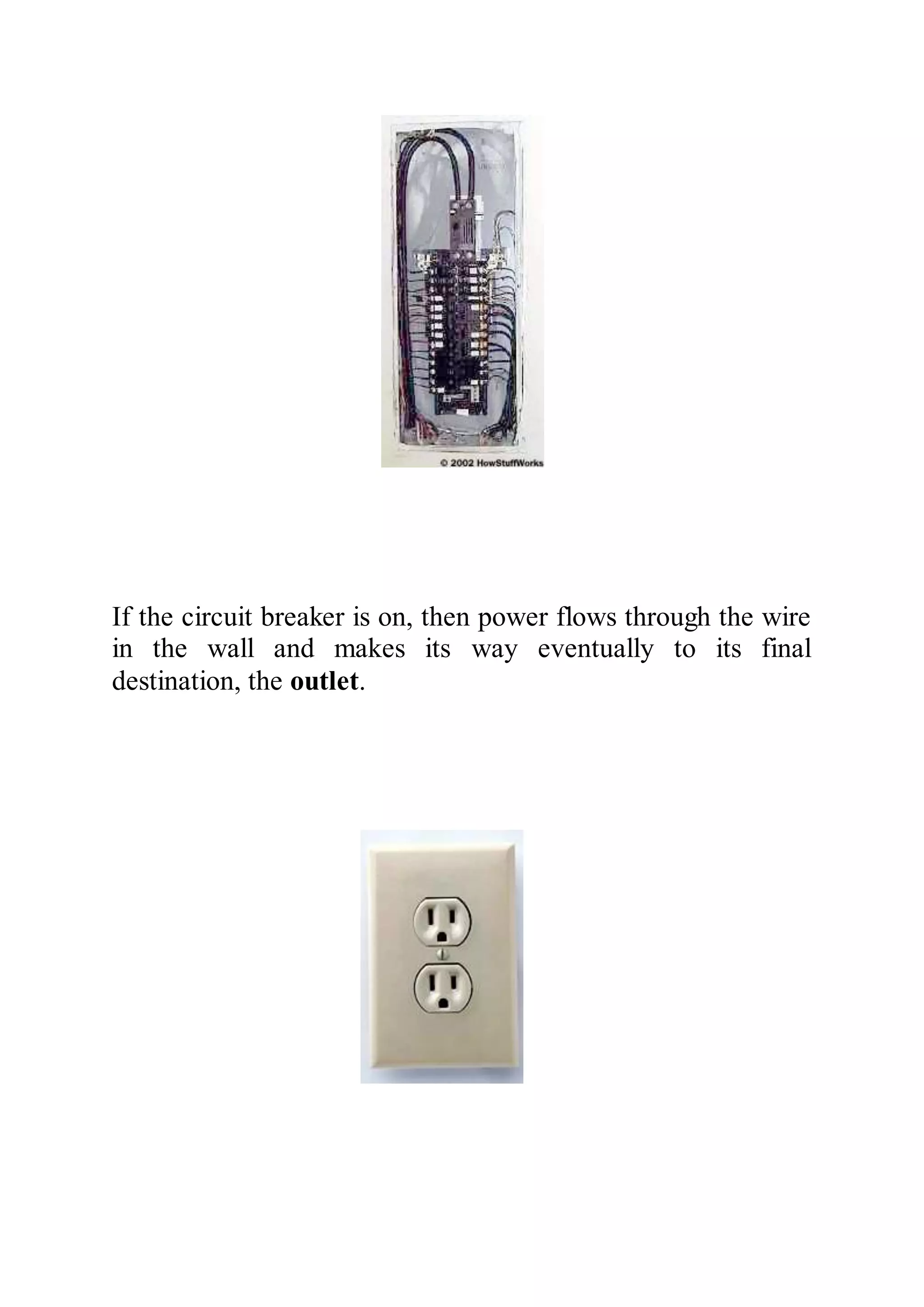
- The document outlines ITI's electricity distribution network within its facilities.