Downloaded 52 times
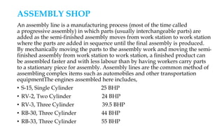
![ASSEMBLY PROCESS FOLLOWED AT SHOP
• CRANK SHAFT FITMENT
• CAM SHAFT FITMENT
• GEAR CASING FITMENT
• CRITICAL AREA PISTON ASSEMBLY
• CYLINDER BLOCK FITMENT
• OIL SUMP FITMENT
• CYLINDER HEAD FITMENT
• WATER PUMP FITMENT
• FIP [FUEL INJECTION PUMP] FITMENT
• FUEL TIMING](https://image.slidesharecdn.com/f65e0ca5-83cd-4deb-88ad-6d6f519969d1-150710071234-lva1-app6891/85/training-ppt-6-320.jpg)
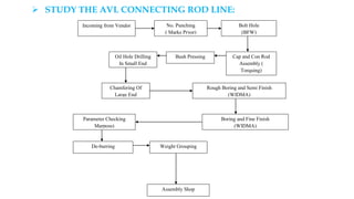


The document provides details about Atul Malhotra's semester training at Swaraj Engines Limited in Mohali, India. It includes: - An introduction to Swaraj Engines Limited, describing its establishment and production of diesel engines. - An overview of the various departments, including the Assembly Shop where Atul was trained. - Details of Atul's objectives for the training, which were to gain new skills, study processes, and complete projects under supervision. - A description of key tasks Atul carried out, such as analyzing the bumping process to set piston clearance and studying the production line for connecting rods.


