2
Objectives
In thislecture, we explore what computer graphics is
about and survey some application areas
We start with a historical introduction
3.
3
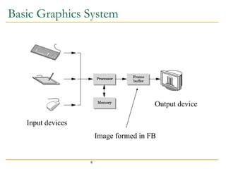
Computer Graphics
Computergraphics deals with all aspects of creating
images with a computer
Hardware
Software
Applications
4.
4
Example
Where didthis image come from?
What hardware/software did we need to produce it?
5.
5
Preliminary Answer
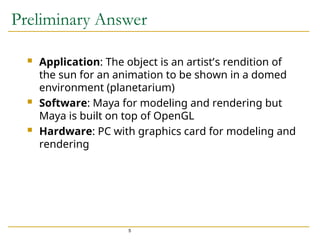
Application:The object is an artist’s rendition of
the sun for an animation to be shown in a domed
environment (planetarium)
Software: Maya for modeling and rendering but
Maya is built on top of OpenGL
Hardware: PC with graphics card for modeling and
rendering
7
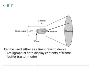
CRT
Can be usedeither as a line-drawing device
(calligraphic) or to display contents of frame
buffer (raster mode)
8.
8
Computer Graphics: 1950-1960
Computer graphics goes back to the earliest days of
computing
Strip charts
Pen plotters
Simple displays using A/D converters to go from computer
to calligraphic CRT
Cost of refresh for CRT too high
Computers slow, expensive, unreliable
9.
9
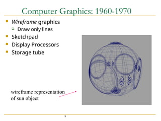
Computer Graphics: 1960-1970
Wireframe graphics
Draw only lines
Sketchpad
Display Processors
Storage tube
wireframe representation
of sun object
10.
10
Sketchpad
Ivan Sutherland’sPhD thesis at MIT
Recognized the potential of man-machine interaction
Loop
Display something
User moves light pen
Computer generates new display
Sutherland also created many of the now common
algorithms for computer graphics
11.
11
Display Processor
Ratherthan have the host computer try to refresh
display use a special purpose computer called a
display processor (DPU)
Graphics stored in display list (display file) on
display processor
Host compiles display list and sends to DPU
12.
12
Direct View StorageTube
Created by Tektronix
Did not require constant refresh
Standard interface to computers
Allowed for standard software
Plot3D in Fortran
Relatively inexpensive
Opened door to use of computer graphics for CAD
community
13.
13
Computer Graphics: 1970-1980
Raster Graphics
Beginning of graphics standards
IFIPS
GKS: European effort
Becomes ISO 2D standard
Core: North American effort
3D but fails to become ISO standard
Workstations and PCs
14.
14
Raster Graphics
Imageproduced as an array (the raster) of picture
elements (pixels) in the frame buffer
16
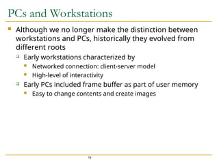
PCs and Workstations
Although we no longer make the distinction between
workstations and PCs, historically they evolved from
different roots
Early workstations characterized by
Networked connection: client-server model
High-level of interactivity
Early PCs included frame buffer as part of user memory
Easy to change contents and create images
19
Computer Graphics: 1990-2000
OpenGL API
Completely computer-generated feature-length movies
(Toy Story) are successful
New hardware capabilities
Texture mapping
Blending
Accumulation, stencil buffers
20.
20
Computer Graphics: 2000-2010
Photorealism
Graphics cards (GPU) for PCs dominate market
Nvidia, ATI
Game boxes and game players determine direction of
market (Wii, Kinect, etc)
Computer graphics routine in movie industry: Maya,
Lightwave
Programmable pipelines
21.
21
Computer Graphics: 2010-
Mobile Computing
iPhone
Cloud Computing
Amazon Web Services (AWS)
Virtual Reality
Oculus Rift
Artificial Intelligence
Big Data/Deep Learning
Google Car