Download as PDF, PPTX


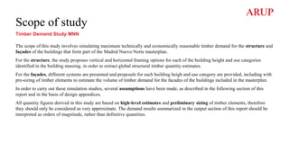


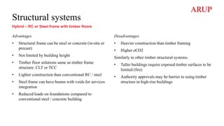


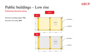
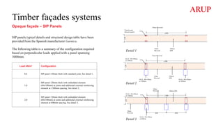
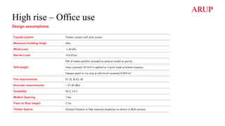

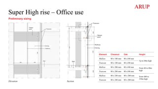
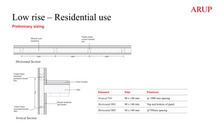
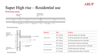


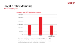

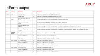

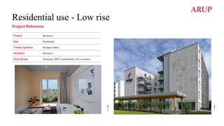
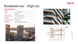
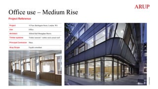

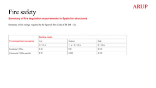
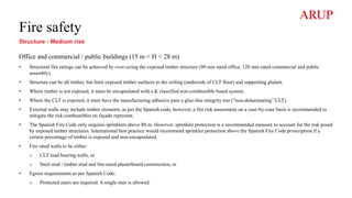
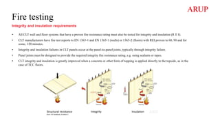
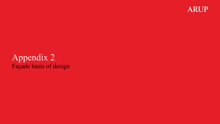
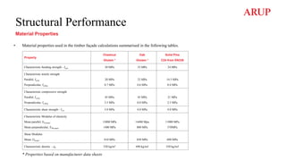
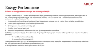
![The thermal transmittance (U) of each element belonging to the thermal envelope shall not exceed the limit value (Ulim) of the following table
3.1.1.a-CTE DB HE1
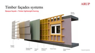
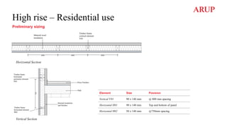
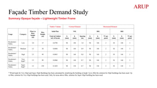
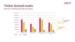
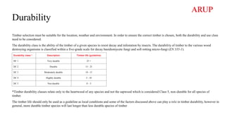
Thermal transmittance used in calculation for the different timber façade systems and other cladding types is summarised in the following table:
Energy Performance
Thermal transmittance of the building envelope for Madrid (Ulim) [W/m2K]
Cladding Winter climatic zone D [W/m2K]
Walls in contact with outside air (US, UM) 0.41
Windows (UH) 1.80
Roof (Us) 0.35
Floor in contact with soild (UT) 0.65
Cladding U [W/m2K]
Timber curtain wall (UM) 1.20
Windows (UH) in residential buldings 1.60
Ligthweigth frame (UM) 0.25
SIP (UM) 0.32
Roof (US) 0.15
Floor in contact with soild (UT) 0.15](https://image.slidesharecdn.com/3-230417133648-b4ddce87/85/Timber-Demand-Study-Report-Structures-and-facade-HCC-EU-CINCO-160-320.jpg)
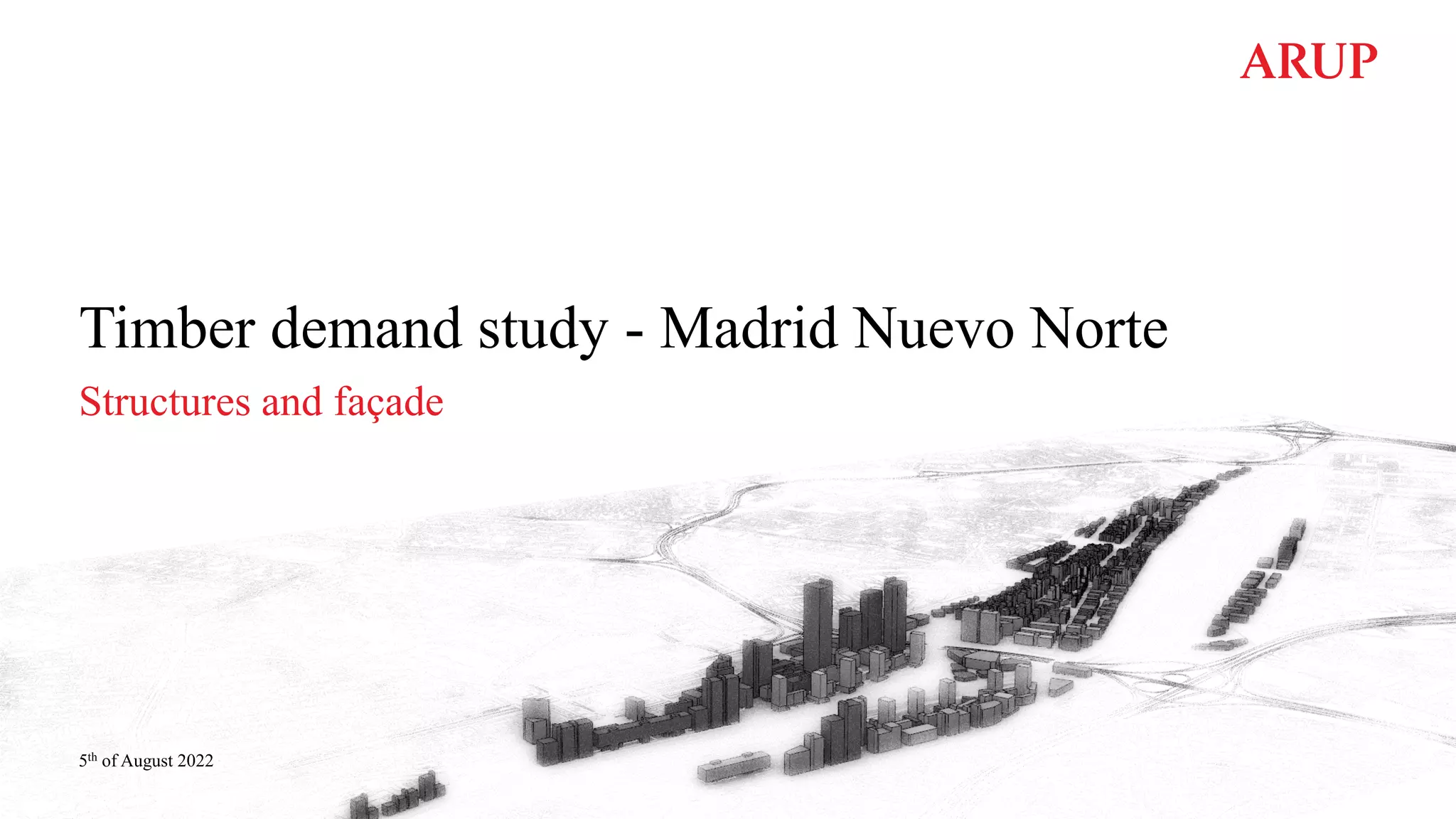
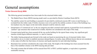
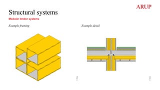
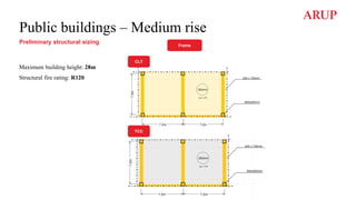
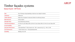
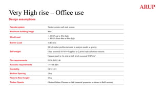
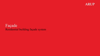
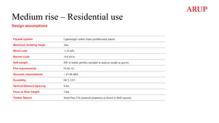
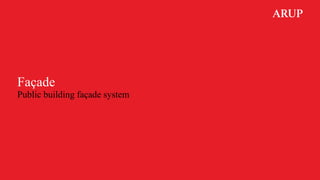
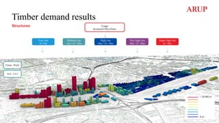
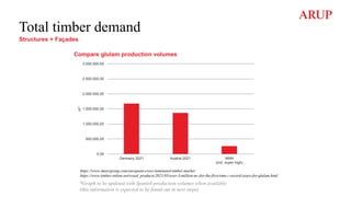
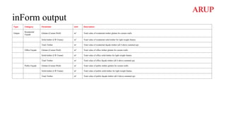
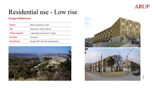
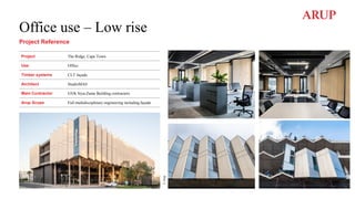
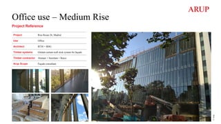
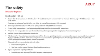
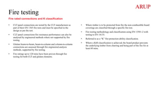
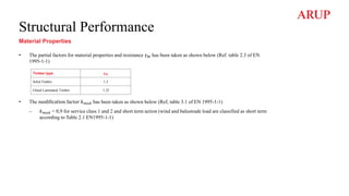
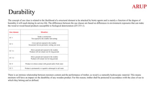
![Energy Performance
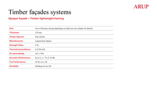
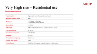
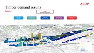
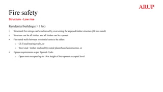
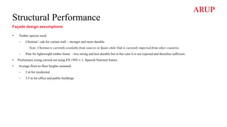
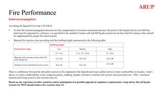
Overall heat transfer coefficient (K) [W/m2K]
Compacity
V/A [m3/m2]
New buildings
Winter climatic zone D [W/m2K]
Commercial building Residential building
V/A ≤ 1 0.54 0.48
V/A ≥ 4 0.70 0.67
The overall heat transmission coefficient through the building envelope (K) shall not exceed the limit value (Klim) obtained from table 3.1.1.b and C-
CTE DB HE1:
Compacity (V/A): Ratio of the volume enclosed by the thermal envelope (V) of the building (or part of the building) to the sum of the heat exchange
surfaces with the outside air (or part of the building) and the sum of the heat exchange surfaces with the outside air or ground of the building
envelope (A = ΣAi), of the thermal envelope (A = ΣAi). It is expressed in m³/m².
The overall heat transfer coefficient have been calculated for different scenarios of compacity and WWR:
• Office building V/A ≥ 4 – WWR 60 – 70 % (60% transparent area/ 40% opaque area; 70% transparent area/ 30% opaque area)
• Office building V/A ≤ 1 – WWR 50% (50% transparent area/ 50% opaque area)
• Residential building V/A ≥ 4 – WWR 40 – 50 - 60%](https://image.slidesharecdn.com/3-230417133648-b4ddce87/85/Timber-Demand-Study-Report-Structures-and-facade-HCC-EU-CINCO-161-320.jpg)
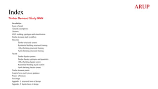
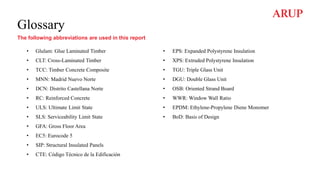
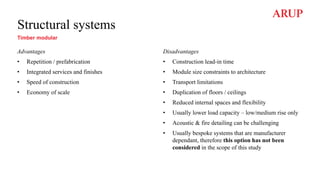
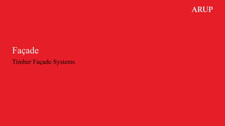
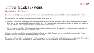
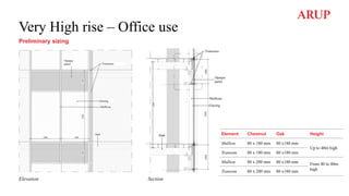
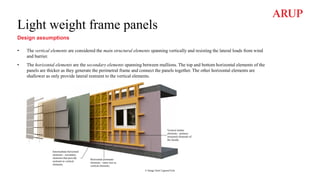
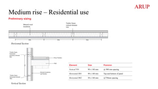
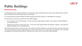
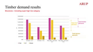
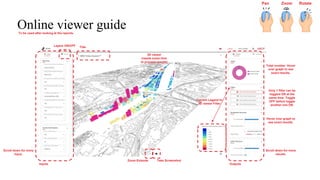
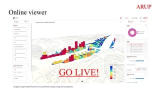
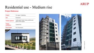
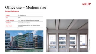
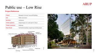
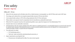
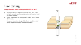
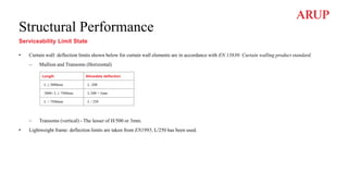
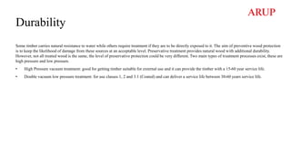
![Energy Performance
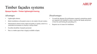
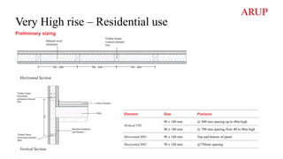
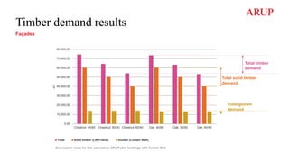
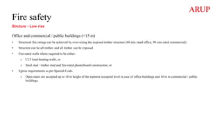
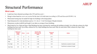
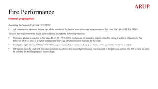
Airtightness (Q 100,lim [m3/h,m2]) and Limitation of condensation
Two indicators are set to limit uncontrolled air flows through the envelope:
• The windows airtightness will be better than class 3, 9 m3 /h·m2, values according to UNE EN 12207:2017.
• The air change ratio through the thermal envelope of the building at a differential pressure of 50 Pa (n50) shall not exceed the limit value in table
3.1.3.b (HE1). The air change ratio will be checked by testing from method 1 or 2 of UNE-EN ISO 9972:2019 Thermal performance of buildings.
Q 100,lim [m3 /h·m2]
Airtightness (Q 100,lim) ≤ 9
Compacity V/A
[m3/m2]
Limit value of the air change ratio at a pressure of 50 Pa,
n50 [h-1 ]
V/A ≤ 2 6
V/A ≥ 4 3
• All façade systems have incorporated a vapor barrier on the warm side of the façade.](https://image.slidesharecdn.com/3-230417133648-b4ddce87/85/Timber-Demand-Study-Report-Structures-and-facade-HCC-EU-CINCO-162-320.jpg)
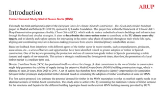
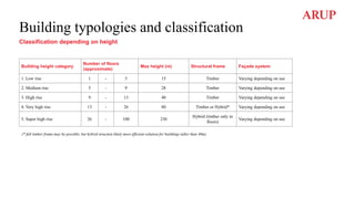
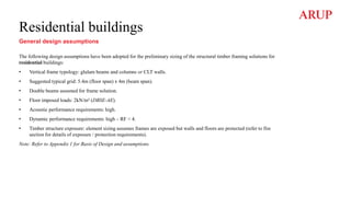
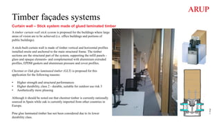
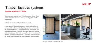
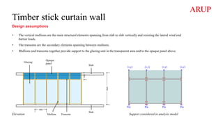
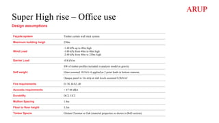
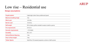
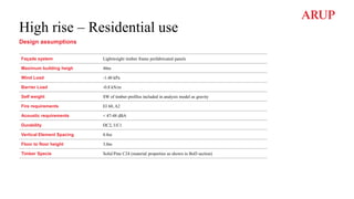
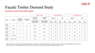
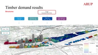
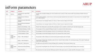
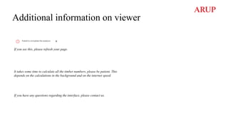
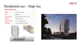
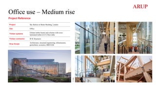
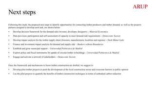
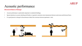
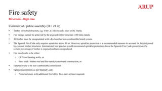
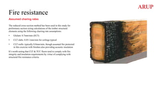
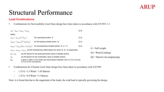
![Acoustic Performance
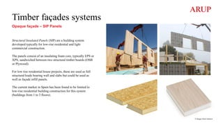
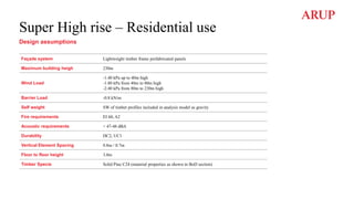
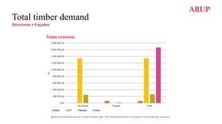
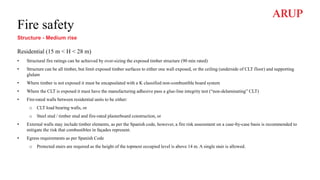
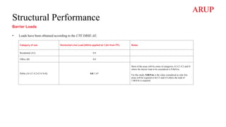
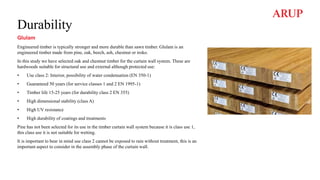
According to the data obtained from the noise map ‘Mapa estratégico de ruido de Madrid 2016’, the buildings will be exposed to daytime noise level up
to 75 dBA.
CTE DB HR set up different noise attenuation requirements against traffic noise based on the daytime noise level, the building use and the WWR. The
following table shows the most demanding attenuation values against traffic noise that must provide the different façades:
Mapa estratégico de ruido de Madrid 2016
Grandes ejes A1 D05, Chamartín
Cladding RAtr [dBA]
Residential buildings- Façade 47-48
Residential buildings- Windows 55-60
Commercial buildings- CW 47-48](https://image.slidesharecdn.com/3-230417133648-b4ddce87/85/Timber-Demand-Study-Report-Structures-and-facade-HCC-EU-CINCO-163-320.jpg)

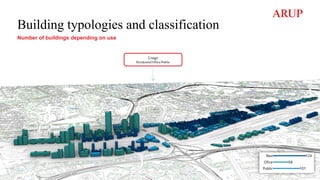
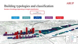
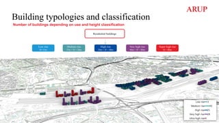
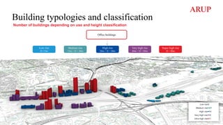
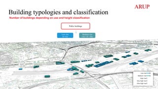
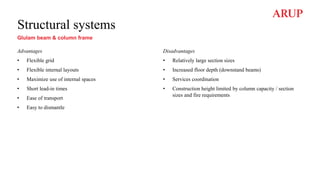
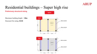
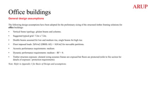
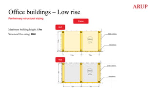
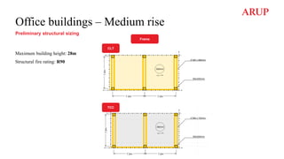
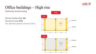
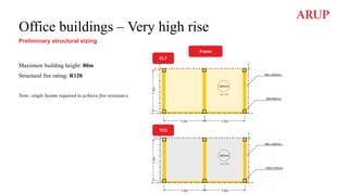
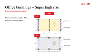
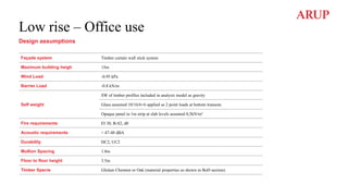
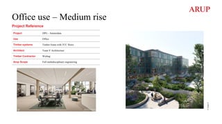
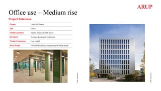
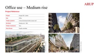
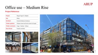
The timber demand study for the Madrid Nuevo Norte (MNN) aims to estimate the potential timber demand for structures and façades as part of a climate-neutral construction initiative. It explores barriers and opportunities for adopting timber in Spanish construction, emphasizes the need for a stable local timber market, and outlines a 20-year construction plan from 2025 to 2045. The study also categorizes building typologies and presents structural framing options, calling for simulations to assess maximum timber demand across various building scenarios.