Downloaded 94 times


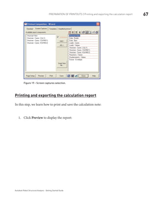
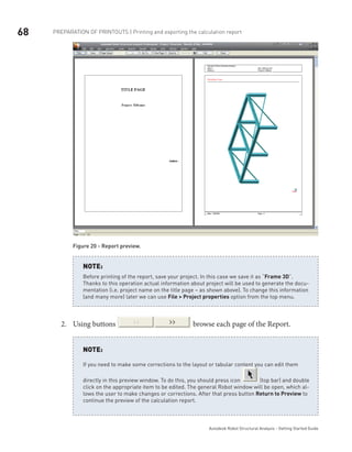
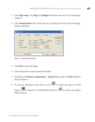
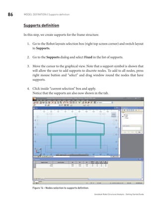
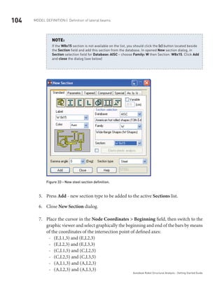
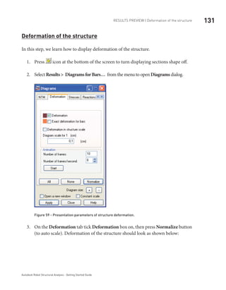
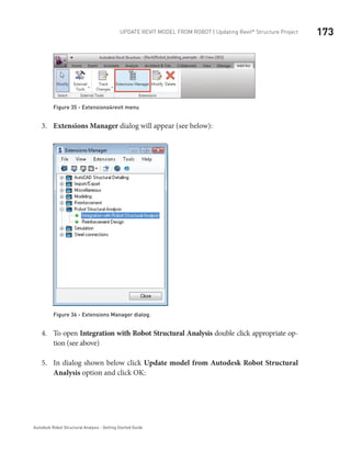
![44 MODEL DEFINITION | Bars definition
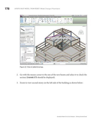
Autodesk Robot Structural Analysis - Getting Started Guide
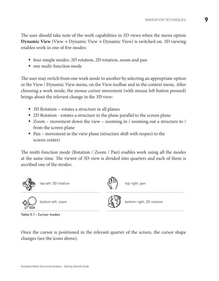
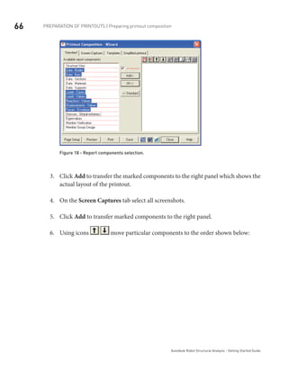
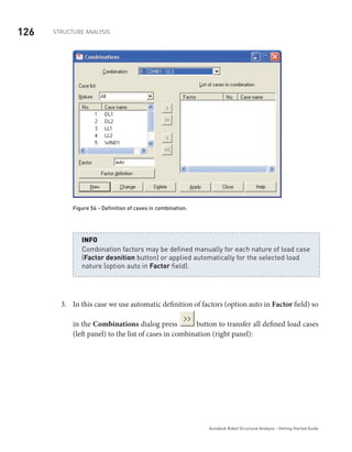
Regional settings set the default databases (profiles, materials), units and codes to the stan-
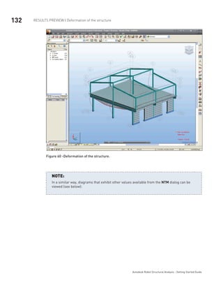
dards of a country. In the example above, we have chosen American section database (AISC)
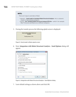
and metric data units: [m],[cm], [kN].
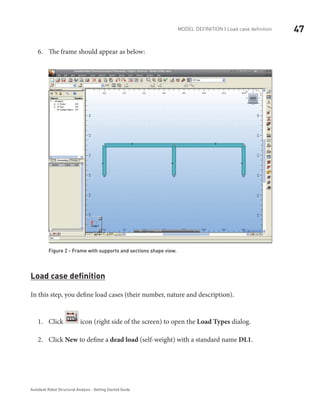
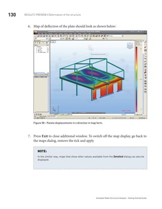
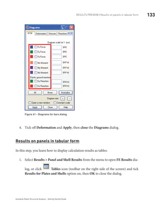
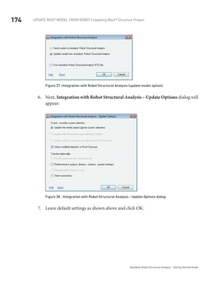
NOTE:
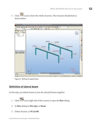
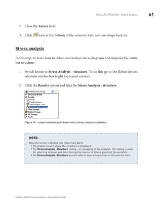
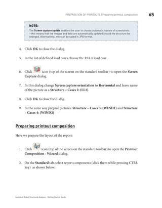
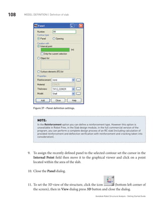
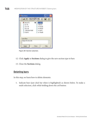
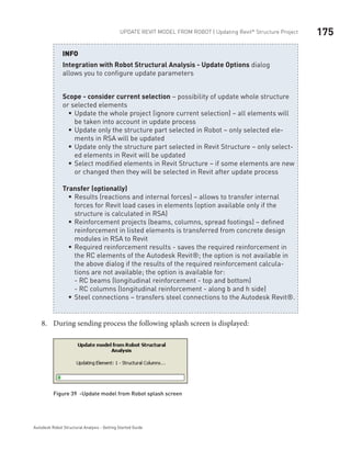
Click5. Accept to close the window.
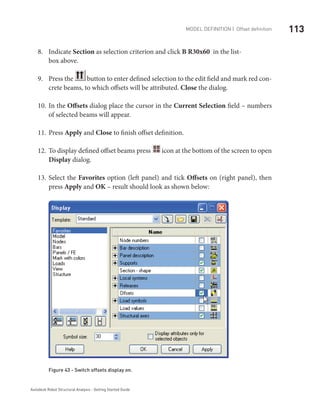
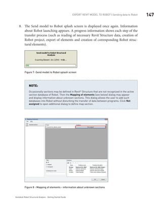
You can check active units in right, bottom corner of the screen. In this example should be
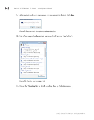
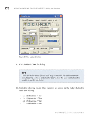
the display: [m] [kN] [Deg].
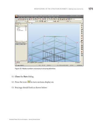
NOTE:
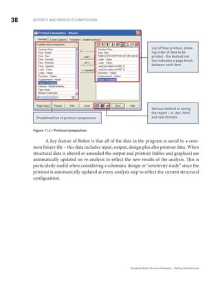
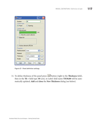
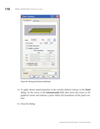
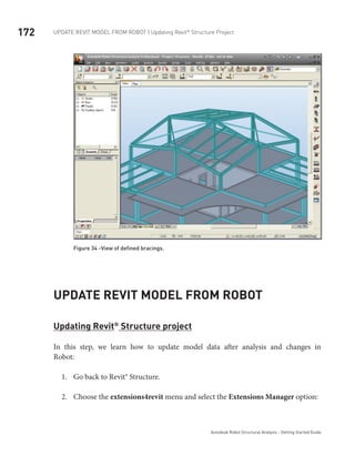
Model Definition
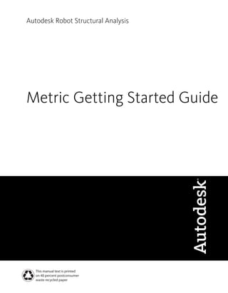
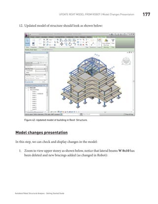
Bars definition (frame 2D)
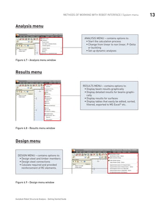
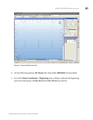
In this step, you create frame members consisting of 2 columns and a beam.
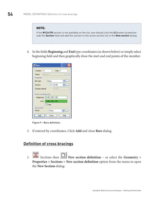
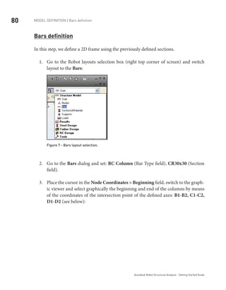
Click1. icon (right side of the screen) to open the Bars dialog.
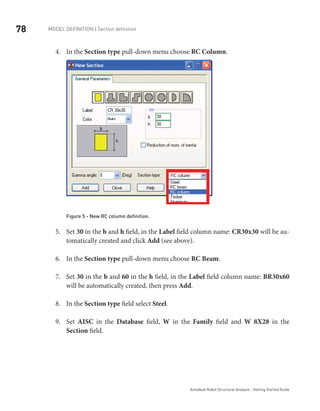
Set2. Bar type: as Column – whatever is selected is not important for analysis, but
affects the design parameters for subsequent member design, such a buckling
length, position of restraint etc.
Define3. Section: as W14x211.](https://image.slidesharecdn.com/robotkhmerengineer-181024160405/85/Robot-khmer-engineer-50-320.jpg)
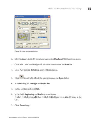

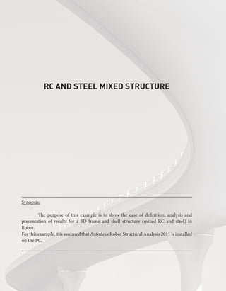

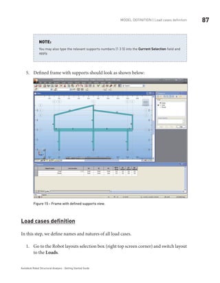
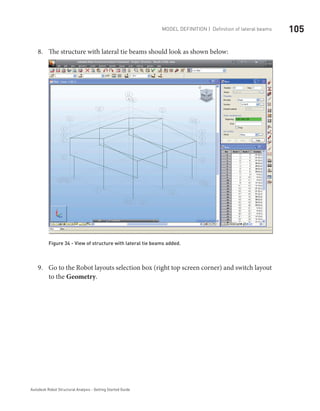
![74 Model definition | Definition of structural axes
Autodesk Robot Structural Analysis - Getting Started Guide
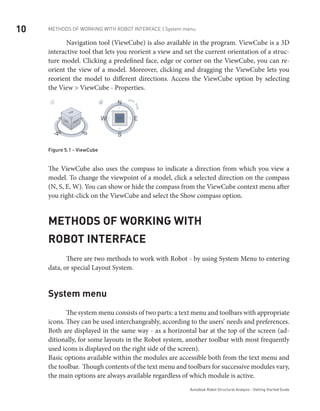
Regional settings set the default databases (profiles, materials), units and codes to the stan-
dards of a country. In the example above, we have chosen American section database (AISC)
and metric data units: [m],[cm], [kN].
NOTE:
Click5. Accept to close the window
You can check active units in right, bottom corner of the screen. In this example should be
the display: [m] [kN] [Deg].
NOTE:
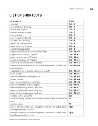
Model definition
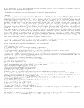
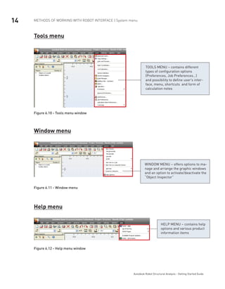
Definition of structural axes
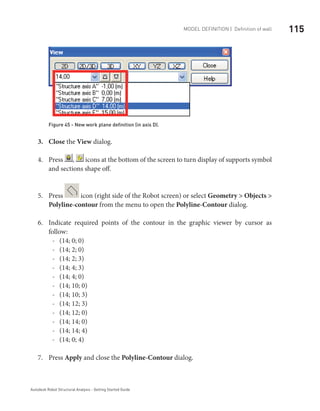
In this step, we define a rectangular axis grid in the Cartesian coordinate system.
The axes of the structure create an additional grid which can be used to
define different elements of the structure and select structure compo-
nents.
The grid intersections form points that facilitate the users work by guiding
cursor movements during graphical structure definition.
INFO
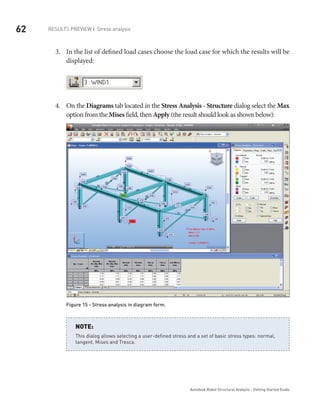
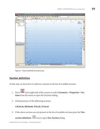
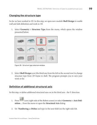
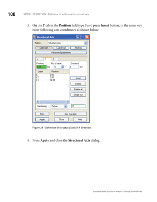
Press1. icon (right side of the Robot screen) or select Geometry > Axis Defi-
nition… from the menu to open the Structural Axis dialog.](https://image.slidesharecdn.com/robotkhmerengineer-181024160405/85/Robot-khmer-engineer-80-320.jpg)


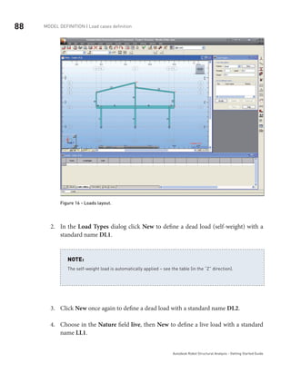
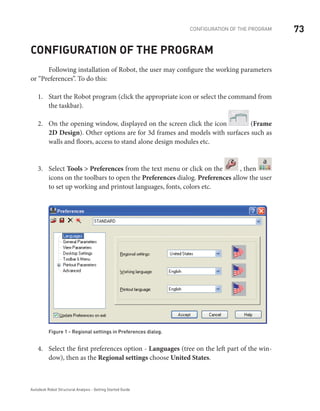
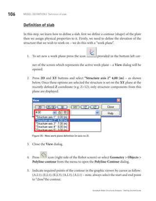
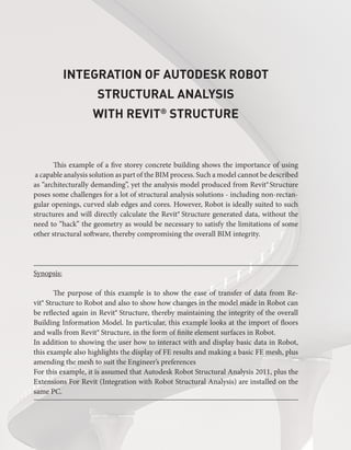
![90 Model definition | Definition of loads for predefined load cases
Autodesk Robot Structural Analysis - Getting Started Guide
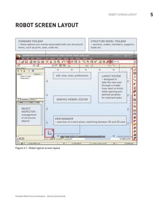
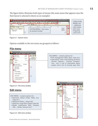
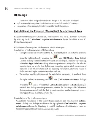
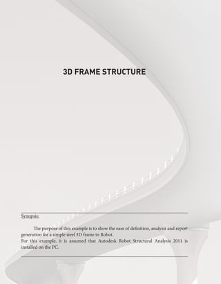
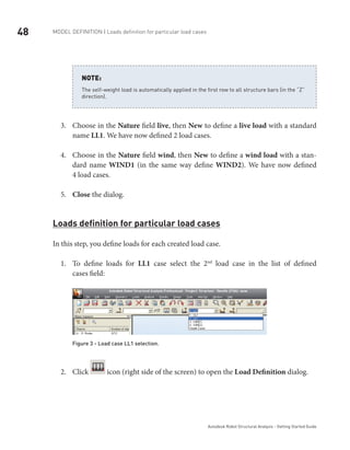
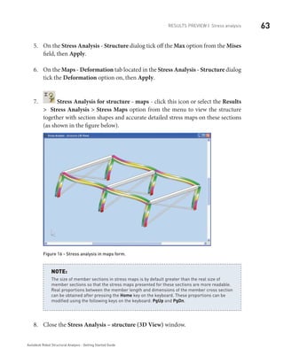
Figure 18 - DL2 load type selection.
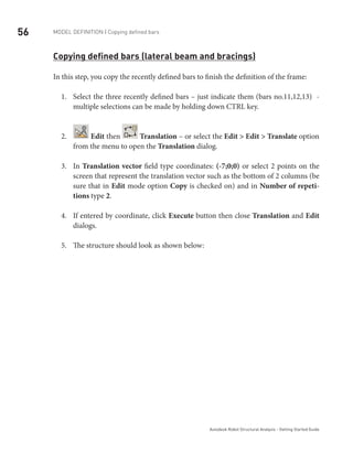
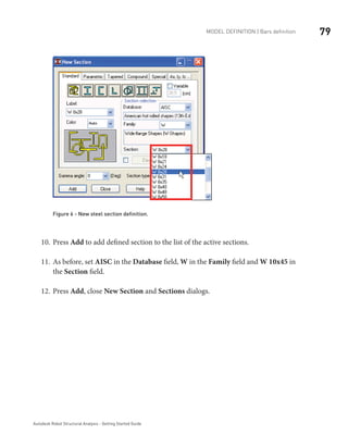
Press2. icon (right side of the screen) to open the Load Definition dialog.
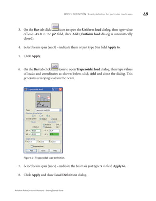
On the3. Bar tab press icon to open Uniform load dialog, then type value of
load –10 [kN/m] in the pZ field, click Add and close the dialog:
Figure 19 - Uniform load definition for DL2 case.
Select beams4. (no. 4 5 6 7) – indicate them or just type 4to7 in field Apply to and
click Apply (as before its possible to window them too).](https://image.slidesharecdn.com/robotkhmerengineer-181024160405/85/Robot-khmer-engineer-96-320.jpg)
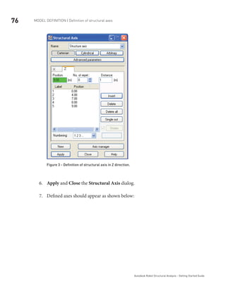
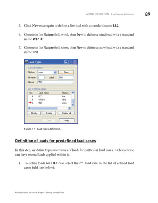
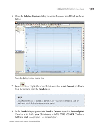
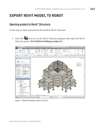
![91Model definition | Definition of loads for predefined load cases
Autodesk Robot Structural Analysis - Getting Started Guide
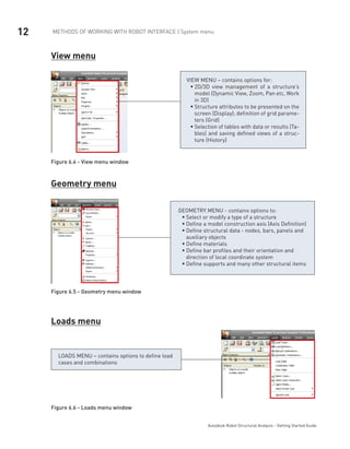
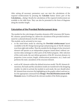
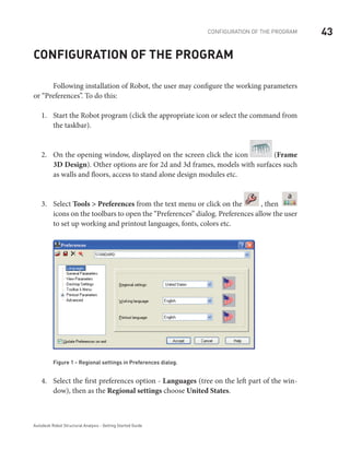
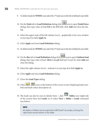
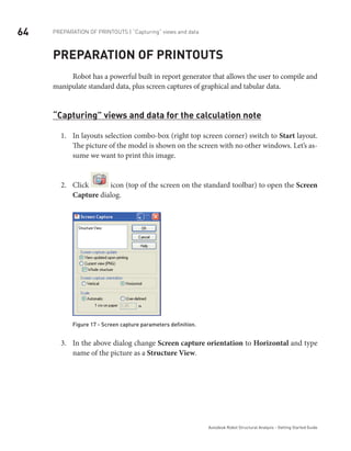
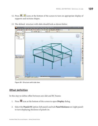
Press5. icon at the bottom of the screen to turn display Load value
descriptions on.
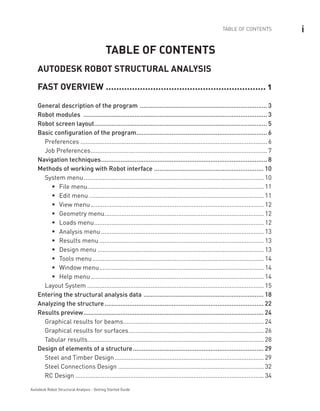
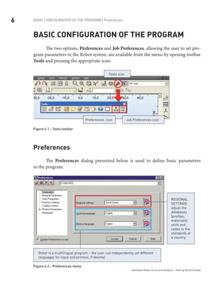
Figure 20 - DL2 load case view.
To define loads for6. LL1 case select the 3rd
load case in the list of defined load
cases field.
On the7. Bar tab press icon to open Bar Force dialog, then type value of load
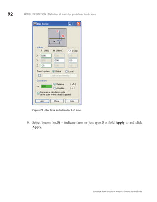
–20 [kN] in the FZ field.
On the8. Coordinate field leave x=0,50 value (defined force will be applied halfway
along the member), click Add and Close the dialog.](https://image.slidesharecdn.com/robotkhmerengineer-181024160405/85/Robot-khmer-engineer-97-320.jpg)
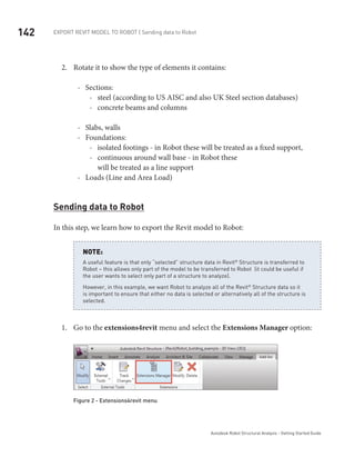
![93Model definition | Definition of loads for predefined load cases
Autodesk Robot Structural Analysis - Getting Started Guide
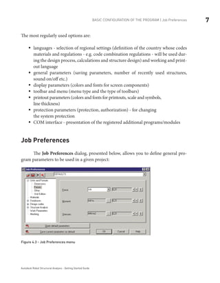
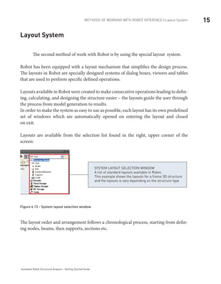
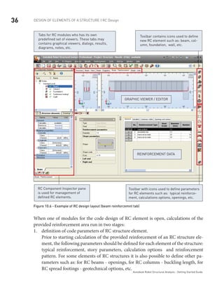
Figure 22 - LL1 load case view.
In the same way you may define for10. 4th
: LL2 load case bar force –30 [kN] on the
half length of the bar No.6.](https://image.slidesharecdn.com/robotkhmerengineer-181024160405/85/Robot-khmer-engineer-99-320.jpg)
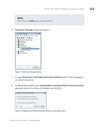
![94 Model definition | Definition of loads for predefined load cases
Autodesk Robot Structural Analysis - Getting Started Guide
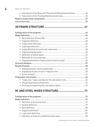
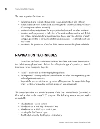
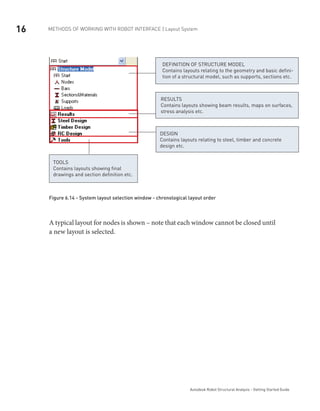
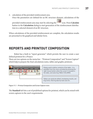
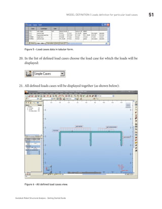
Figure 23 - LL2 load case view.
To define loads for11. WIND1 case select the 5th
load case in the list of defined load
cases field.
On the12. Bar tab press icon to open Uniform Load dialog, then type value of
load –1,5 [kN/m] in the pZ field, tick Coord. system – Local on, then click Add
and close the dialog.](https://image.slidesharecdn.com/robotkhmerengineer-181024160405/85/Robot-khmer-engineer-100-320.jpg)
![95Model definition | Definition of loads for predefined load cases
Autodesk Robot Structural Analysis - Getting Started Guide
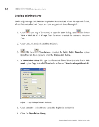
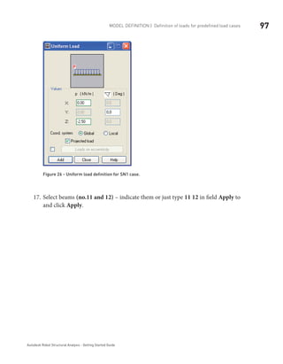
Figure 24 - Uniform load definition for WIND1 case.
Select beam13. (no.1) – indicate them or just type 1 in field Apply to and click
Apply.
In the same way define uniform loads:14. -2,50 [kN/m] for bar no. 8 and -3 [kN/m]
for bar no. 11.](https://image.slidesharecdn.com/robotkhmerengineer-181024160405/85/Robot-khmer-engineer-101-320.jpg)
![96 Model definition | Definition of loads for predefined load cases
Autodesk Robot Structural Analysis - Getting Started Guide
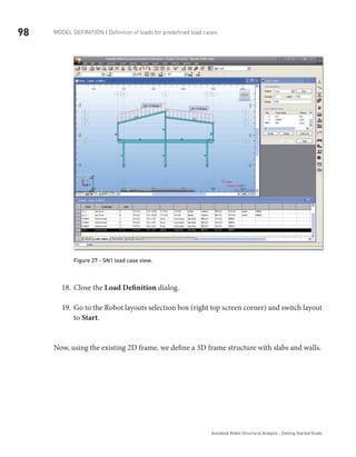
Figure 25 - WIND1 load case view.
To define loads for15. SN1 case select the 6th
load case in the list of defined load
cases field.
On the16. Bar tab press icon to open Uniform Load dialog, then type value
of load –2,50 [kN/m] in the pZ field, tick Projected load on, then click Add and
close the dialog.](https://image.slidesharecdn.com/robotkhmerengineer-181024160405/85/Robot-khmer-engineer-102-320.jpg)
![111Model definition | Offset definition
Autodesk Robot Structural Analysis - Getting Started Guide
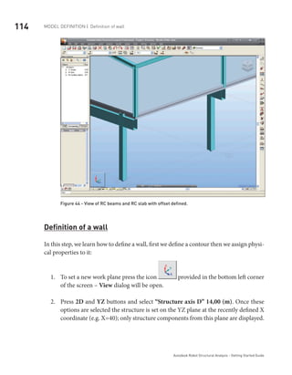
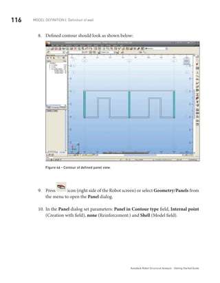
Figure 40 - Default view of RC beams and RC slab on the same level with no eccentricity.
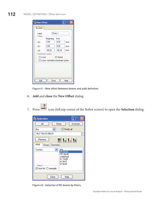
Select4. Geometry > Additional Attributes > Offsets… from the menu then press
New offset definition button to open the New Offset dialog.
In the5. New Offset dialog set parameters: Offset_1 in Label field, -45,24 [cm]
(this is half of RC slab height plus half of RC beams height) in the Beginning
– UZ: and End - UZ: fields and tick Global (Coordinate system field) on - see
picture below:](https://image.slidesharecdn.com/robotkhmerengineer-181024160405/85/Robot-khmer-engineer-117-320.jpg)
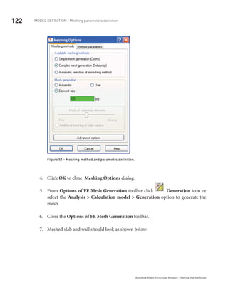
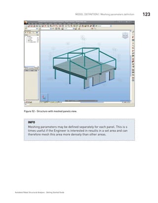
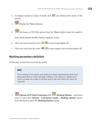
![121Model definition | Meshing parameters definition
Autodesk Robot Structural Analysis - Getting Started Guide
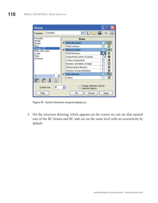
1. Options of FE Mesh Generation then Meshing Options – click
these icons or select the Analysis > Calculation model > Meshing Options op-
tion from the menu to open the Meshing Options dialog.
Select2. Complex mesh generation (Delaunay) to choose meshing method.
Type3. 0,5 [m] to define size of finite elements (as shown below):
Because there were no panels selected, the program will ask you the question:
Answer Yes to select all panels.
NOTE:](https://image.slidesharecdn.com/robotkhmerengineer-181024160405/85/Robot-khmer-engineer-127-320.jpg)
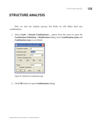


![149Structure Analysis in ROBOT
Autodesk Robot Structural Analysis - Getting Started Guide
Structure Analysis in Robot
Change units from imperial to metric: Tools/Job Preferences/Units and Formats/Metric.
You can check active units in right, bottom corner of the screen. In this example should be
the display: [m] [kN] [Deg].
NOTE:
Exported Revit®
model of structure should appear in Robot as shown below:
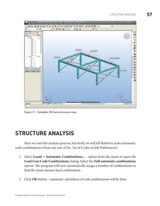
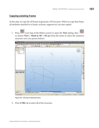
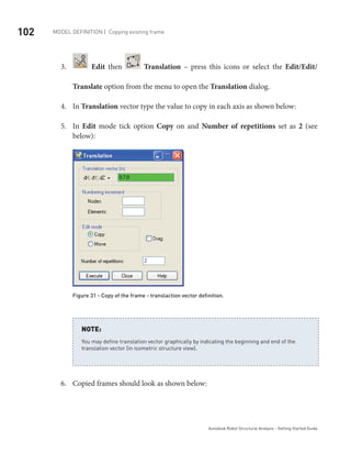
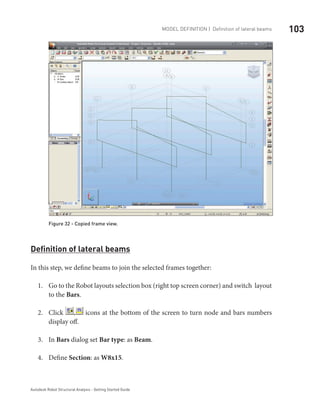
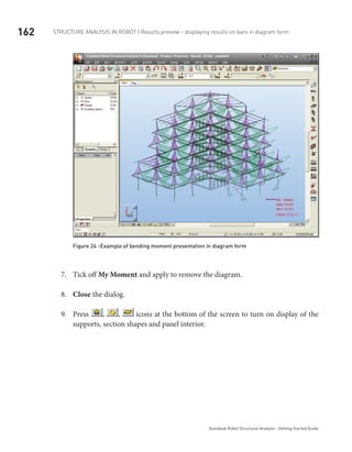
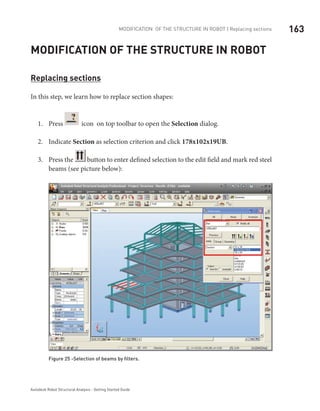
Figure 11 -Exported model of structure in Robot](https://image.slidesharecdn.com/robotkhmerengineer-181024160405/85/Robot-khmer-engineer-155-320.jpg)
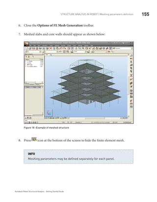
![154 Structure Analysis in ROBOT | Meshing parameters definition
Autodesk Robot Structural Analysis - Getting Started Guide
NOTE:
Because there were no panels selected, the program will ask you the question:
Answer Yes to select all panels.
Select2. Complex mesh generation (Delaunay) to choose meshing method.
Type3. 0,61 [m] to define size of finite elements (as shown below):
Figure 17 -Meshing method selection
Click OK to close4. Meshing Options dialog.
From5. OptionsofFEMeshGenerationtoolbarclick Generationsicon orselect
the Analysis > Calculation model > Generation option to generate the FE mesh.](https://image.slidesharecdn.com/robotkhmerengineer-181024160405/85/Robot-khmer-engineer-160-320.jpg)
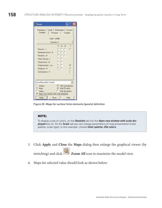
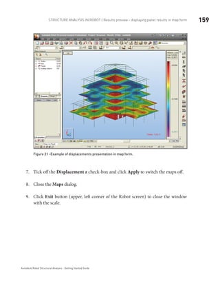
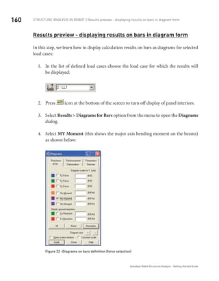
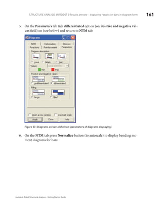


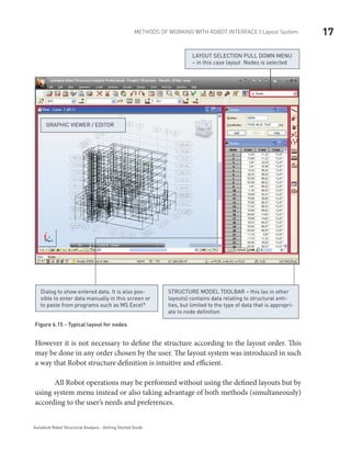
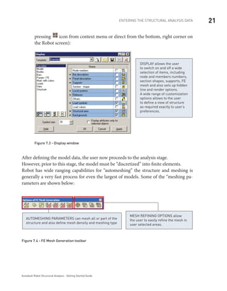
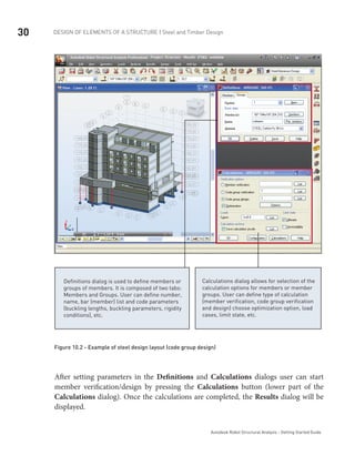
This guide provides a fast overview of the key features and functionality of Autodesk Robot Structural Analysis. It describes the general program layout and modules, how to navigate the interface, enter structural analysis data, run analyses, view and interpret results, design structural elements, and generate reports. The guide also includes a list of keyboard shortcuts.


