
Recommended
More Related Content
What's hot
What's hot (18)
Similar to Thesis L Leyssenne - November 27th 2009 - Part2
Similar to Thesis L Leyssenne - November 27th 2009 - Part2 (20)
Thesis L Leyssenne - November 27th 2009 - Part2
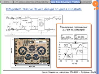
- 1. Intro. Conclusion PA discretized reconfigurability Gate Bias Envelope Tracking 1 Integrated Passive Device design on glass substrate S-parameters measurement (5W diff. to 50W single) Laurent Leyssenne – November 27th 2009 – Bordeaux – Part 2
- 2. Intro. Conclusion PA discretized reconfigurability Gate Bias Envelope Tracking 2 Envelope Tracking Principle Goal: making DC consumption follow envelope variations Adaptive control of power supply (VDD) or Adaptive control of Current consumption (IDD) Issues/requirements: Reduced die area / complexity / Bill-Of-Material Immunity on linearity and noise performances Wide channel bandwidth to address 3G/4G and latest RF standards. Accurate reconfiguration of envelope tracking behavior to optimize simultaneously linearity/ and efficiency. Laurent Leyssenne – November 27th 2009 – Bordeaux – Part 2
- 3. Intro. Conclusion PA discretized reconfigurability Gate Bias Envelope Tracking 3 Envelope Tracking general synoptic General envelope tracking architecture (gate et drain control) Efficient but based on DC/DC converter: • Difficult to integrate • Increased Bill-Of-Material (at least 1 ext. Choke required) Dynamic gate bias: • Low complexity • Low BOM • Low silicon Option considered Laurent Leyssenne – November 27th 2009 – Bordeaux – Part 2
- 4. Intro. PA discretized reconfigurability IDD Bias Envelope TrackingConclusion 4 Reconfigurable-Depth adaptive Bias technique IDD adaptive bias modifies PA properties Impact on AM/AM and AM/PM 1st-order base-band current law in classic IDD adaptive bias systems: I DD I DDQ h Vg2,RF where h is fixed-valued and presents minor frequency dependence . Proposed reconfigurable-depth adaptive bias law: I DD I DDQ ηDEPTHVDEPTH , Δω Vg2,RF where hDEPTH is frequency-controlled and voltage-controlled by VDEPTH If VDEPTH is power dependent 2nd-order system with respect to power Laurent Leyssenne – November 27th 2009 – Bordeaux – Part 2
- 5. Intro. PA discretized reconfigurability IDD Bias Envelope TrackingConclusion 5 Reconfigurable-Depth adaptive Bias technique Dual adaptive bias system (patent pending) Coarse adaptive bias: Diode-connected LDMOS linearizer VSWR mismatch sensitive (PA protection purpose) Inserted in a closed-loop for increased channel bandwidth and better robustness Fine tuning adjustable bias (for reconfiguration depth) Includes a power detector featuring an negative to positive Voltage- Controlled Gain Includes a reconfigurable base-band filter to: control the phase of the injected envelope harmonics cancel / magnify memory effects balance / unbalance lower and upper spectral regrowth The control of PA response in base-band domain is of crucial importance in the prospect of linearity immunity. Laurent Leyssenne – November 27th 2009 – Bordeaux – Part 2
- 6. Intro. Conclusion PA discretized reconfigurability Gate Bias Envelope Tracking 6 Reconfigurable-Depth Adaptive Bias LDMOS PA schematic Envelope probe node LDMOS linearizer Zero for wider bandwidth LDMOS linearizer Laurent Leyssenne – November 27th 2009 – Bordeaux – Part 2
- 7. Intro. PA discretized reconfigurability IDD Bias Envelope TrackingConclusion 7 Base-band building blocks: Variable-Gain Mixer V sinh2 IN 2U I OUT I OUT I BIAS t tanh VADJ VIN 2U cosh t 2U t Laurent Leyssenne – November 27th 2009 – Bordeaux – Part 2
- 8. Intro. PA discretized reconfigurability IDD Bias Envelope TrackingConclusion 8 Dual-tone illustration of linearity improvement via reconfigurable-depth adaptive Bias (a) 3rd degree non-linearities (red harmonics) tend to compress the magnitude of the output power (gm3<0). Laurent Leyssenne – November 27th 2009 – Bordeaux – Part 2
- 9. Intro. PA discretized reconfigurability IDD Bias Envelope TrackingConclusion 9 Dual-tone illustration of linearity improvement via reconfigurable-depth adaptive Bias (b) The power detector generates an envelope signal that modulates the base-band gate voltage (green harmonics) with an adjustable conversion gain. Laurent Leyssenne – November 27th 2009 – Bordeaux – Part 2
- 10. Intro. PA discretized reconfigurability IDD Bias Envelope TrackingConclusion 10 Dual-tone illustration of linearity improvement via reconfigurable-depth adaptive Bias (c) Base-band gate voltage harmonics combine with RF harmonics via power transistor 2nd–order non-linearities (blue harmonics) and combat 3rd degree non-linearities (gm3<0<gm2) Laurent Leyssenne – November 27th 2009 – Bordeaux – Part 2
- 11. Intro. PA discretized reconfigurability IDD Bias Envelope TrackingConclusion 11 Dual-tone illustration of linearity improvement via reconfigurable-depth adaptive Bias (d) When the injected envelope magnitude exceeds a threshold level, over-compensation is observed linearity is degraded. Laurent Leyssenne – November 27th 2009 – Bordeaux – Part 2
- 12. Intro. PA discretized reconfigurability IDD Bias Envelope TrackingConclusion 12 Dual-tone illustration of linearity degradation / improvement due to slow rate memory effects (a) Importance of memory effects: Phase shifts in envelope injection Spectral regrowth unbalance Vectorial illustration on IMD3 No memory effect Lower and upper IMD3 balance Laurent Leyssenne – November 27th 2009 – Bordeaux – Part 2
- 13. Intro. PA discretized reconfigurability IDD Bias Envelope TrackingConclusion 13 Dual-tone illustration of linearity degradation / improvement due to slow rate memory effects (b) Importance of memory effects: Phase shifts in envelope injection Spectral regrowth unbalance Vectorial illustration on IMD3 With memory effects Lower and upper IMD3 unbalanced Laurent Leyssenne – November 27th 2009 – Bordeaux – Part 2
- 14. Intro. PA discretized reconfigurability IDD Bias Envelope TrackingConclusion 14 Effect of reconfigurable depth adaptive bias on 2-tone PA response Locuses of G3/G1 ratio for: • various power levels • various VDEPTH values Minimum G3/G1 ratio locus in green Laurent Leyssenne – November 27th 2009 – Bordeaux – Part 2
- 15. Intro. PA discretized reconfigurability IDD Bias Envelope TrackingConclusion 15 Effect of reconfigurable depth adaptive bias on ACLR and EVM ACLR peaks can be shifted with respect to power EVM notches can be shifted with respect to power Laurent Leyssenne – November 27th 2009 – Bordeaux – Part 2
- 16. Intro. Conclusion PA discretized reconfigurability Gate Bias Envelope Tracking 16 BiCMOS Silicon Power Amplifier A 32dBm differential 2ndG LDMOS PA (100W diff. to 5W diff.) Power stage: (320x20µm)x2 overall gate width Driver stage: (48x20µm)x2 overall gate width Laurent Leyssenne – November 27th 2009 – Bordeaux – Part 2
- 17. Intro. Conclusion PA discretized reconfigurability Gate Bias Envelope Tracking 17 Continuous wave PA performances @1.75GHz (DCS/EDGE) On-wafer singled-ended load-pull PA characterization was performed. Laurent Leyssenne – November 27th 2009 – Bordeaux – Part 2
- 18. Intro. Conclusion PA discretized reconfigurability Gate Bias Envelope Tracking 18 Continuous wave PA performances @1.75GHz (DCS/EDGE) On-wafer singled-ended load-pull PA characterization was performed. Max. PAE=47% PAE @ OCP1=40% OCP1=27.5dBm Laurent Leyssenne – November 27th 2009 – Bordeaux – Part 2
- 19. Intro. Conclusion PA discretized reconfigurability Gate Bias Envelope Tracking 19 Continuous wave PA performances @1.95GHz (WCDMA) OCP1=27.5dBm Max. PAE=57% PAE @OCP1=51% Min. IDD=120mA PAE @OCP1-10dBm=12% Laurent Leyssenne – November 27th 2009 – Bordeaux – Part 2
- 20. Intro. Conclusion PA discretized reconfigurability Gate Bias Envelope Tracking 20 Dynamic PA performances @1.75GHz (DCS/EDGE) 50dBm OIP3 Max. EDGE output 200kHz 2tone power =21dBm spacing Max. EDGE PAE =17% Non symetric phase shift (memory effect) Laurent Leyssenne – November 27th 2009 – Bordeaux – Part 2
- 21. Intro. Conclusion PA discretized reconfigurability Gate Bias Envelope Tracking 21 Dynamic PA performances @1.95GHz (WCDMA) 35dBm OIP3 Max. PAE for slow rate HPSK=43% Max. linear power for slow rate HPSK =26.5dBm @ACLR=33dBc Max. linear power for WCDMA Max. PAE for WCDMA =21dBm @ACLR=33dBc =22% Laurent Leyssenne – November 27th 2009 – Bordeaux – Part 2
- 22. Intro. Conclusion PA discretized reconfigurability Gate Bias Envelope Tracking 22 Effect of reconfigurable depth adaptive bias on linearity Probed HPSK envelope IMD3 can be optimized by a few dB up to 10dB VDEPTH polarity reversal (,,) required for linearity optimization over wide power range Laurent Leyssenne – November 27th 2009 – Bordeaux – Part 2
- 23. Intro. Conclusion PA discretized reconfigurability Gate Bias Envelope Tracking 24 IV. Conclusion & Prospects (a) Many issues are to be considered for PA design: Quantization noise Memory effects … Some were overcome, some others not. Demonstrators have proven to be efficient with some linearity degradation however. 1 national publication: JNM2005 6 international publications: DCIS2004, IMOC2005, BCTM2006, IEEE Topical Workshop on Power Amplifiers for Wireless Communications 2008, RWS2009, SBCCI2009 1 book contribution In Microwave Filters and Amplifiers (2005) 1 patent pending Laurent Leyssenne – November 27th 2009 – Bordeaux – Part 2
- 24. Intro. Conclusion PA discretized reconfigurability Gate Bias Envelope Tracking 25 IV. Conclusion & Prospects (b) Increasing S modulator bandwidth Investigating decimator filter impact, and complexity Taking into account phase noise Combined reconfigurable/cartesian dual-loop Better correction of memory effects Accurate characterizing thermal effect Integration of a fast temperature sensor Integration of base-band filter Reconfiguration of phase advance/delay Laurent Leyssenne – November 27th 2009 – Bordeaux – Part 2
- 25. Intro. Conclusion PA discretized reconfigurability Gate Bias Envelope Tracking 26 Thank you for your attention Laurent Leyssenne – November 27th 2009 – Bordeaux – Part 2