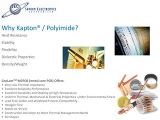
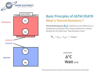
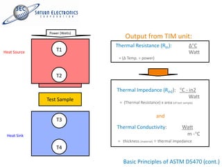
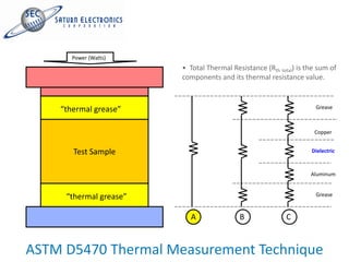
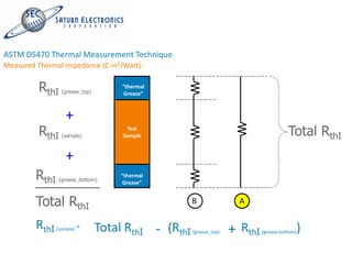
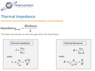
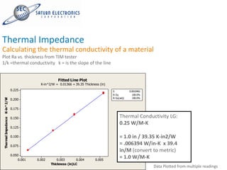
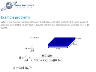
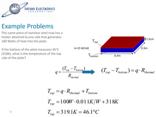
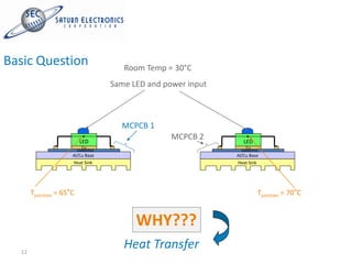
Thermal Transfer
Transfer Heat
Common Callouts include Thermal Impedance / Resistance (°C in2/W) and Thermal Conductivity / (°W/m-K).
Why Kapton® / Polyimide?
Heat Resistance
Stability
Flexibility
Dielectric Properties
Density/Weight


CooLamTM MCPCB (metal core PCB) Offers:
•   Very Low Thermal Impedance
•   Excellent Reliability Performance
•   Excellent Durability and Stability at High Temperature
•   Uniform Thermal, Mechanical & Electrical Properties Under Environmental Stress
•   Lead Free Solder and Wirebond Process Compatibility
•   Halogen Free
•   Meets UL 94 V-0
•   Construction Variations to Meet Thermal Management Needs
•   3D Shapes
Thermal Measurement
Characterize the Thermal Performance of Materials
Objective:
Measuring thermal performance per ASTM D5470.

Equipment:
         1) Steady State “Thermal Interface Material Tester” (TIM)
           (Analysis Tech. Inc.)


Factors to Consider:
         1) Reducing contact resistance between sample and test unit
         2) Repeatability of measured values
         3) Identify any equipment and/or material limitations
Power (Watts)
                                            Basic Principles of ASTM D5470
Heat Source           T1                    What is Thermal Resistance ?
                                            Thermal Resistance (Rth) is defined as the difference in
                                            temperature between two closed isothermal surfaces
                                            divided by the total heat flow between them.
                      T2

                                                        Rth      = (T(A) – T(B))                     Power
    (surface A)

    (surface B)


                      T3

  Heat Sink                                                                            ∆ C
                      T4                                                               Watt (V*I)
                                  * Present system does a good job of accounting for all heat and monitoring temperature but nothing is perfect.
Power (Watts)
                                    Output from TIM unit:
                               Thermal Resistance (Rth):                    ∆ C
Heat Source        T1                                                       Watt
                                = (∆ Temp. power)


                   T2

                               Thermal Impedance (RthI):                C - in2
                                                                            Watt
              Test Sample        = (Thermal Resistance) x area (of test sample)


                                                         and
                   T3
                               Thermal Conductivity:                    Watt
 Heat Sink                                                               m- C
                                = thickness (material)   thermal impedance
                   T4

                                   Basic Principles of ASTM D5470 (cont.)
Power (Watts)
                        • Total Thermal Resistance (Rth total) is the sum of
                        components and its thermal resistance value.


    “thermal grease”                                                 Grease


                                                                    Copper


       Test Sample                                                 Dielectric


                                                                   Aluminum


     “thermal grease”                                                Grease


                          A                B               C


ASTM D5470 Thermal Measurement Technique
Measured Thermal Impedance (C-in2/Watt):


          RthI    (grease_top)
                                      “thermal
                                      Grease”


                   +
          RthI    (sample)
                                       Test
                                      Sample                                             Total RthI
                   +
         RthI   (grease_bottom)
                                     “thermal
                                     Grease”


         Total RthI                                   B                A

         RthI   (sample) =       Total RthI - (RthI   (grease_top)   + RthI   (grease-bottom)   )
Thermal Impedance
Electronics industry defines thermal impedance as the following:

                              thickness
impedance
        thermal
                                  k
This does not include an area through which the heat flows!


            Thermal Impedance                                      Thermal Resistance

                          tDiel                                                     tDiel
                 I                                                         R
                          kDiel                                                    kDielA
        Units:                                                Units:
                     m            m2 K                                     m         K
            I                                                      R           2
                                                                          mK m       W
                                                                        W
                     W
                         mK        W
    8
Thermal Impedance
Calculating the thermal conductivity of a material
Plot Ra vs. thickness from TIM tester
1/k =thermal conductivity k = is the slope of the line


                                                      Fitted Line Plot
                                            K-in^2/W = 0.01366 + 39.35 Thickness (in)
                             0.225                                                      S           0.0010461
                                                                                        R-Sq          100.0%
                                                                                        R-Sq(adj)     100.0%
Thermal Impedance K-in^2/W


                             0.200

                             0.175

                             0.150                                                           Thermal Conductivity LG:
                                                                                             0.25 W/M-K
                             0.125

                             0.100                                                           = 1.0 in / 39.35 K-in2/W
                             0.075
                                                                                             = .006394 W/in-K x 39.4
                                                                                             in/M (convert to metric)
                             0.050
                                  0.001   0.002       0.003      0.004        0.005
                                                                                             = 1.0 W/M-K
                               9                  Thickness (in)LC
                                                                                                                Data Plotted from multiple readings
Example problems
What is the thermal resistance through the thickness of a 0.3 meter by 0.3 meter piece of
stainless steel that is 1.5 cm thick? Assume the thermal conductivity of stainless steel is 15
W/mK.


                              k=15 W/mK                                        1.5cm

                                                                            0.3m
                                t
                         R                                 0.3m
                               kA
                          t           0.015m
                   R
                         kA     (15W mK)(0.3m)(0.3m)

             R    0.011K W
Example Problems
This same piece of stainless steel now has a
heater attached to one side that generates
                                                                                                  1.5cm
100 Watts of heat into the plate.                                  Ttop

If the bottom of the plate measures 45°C            k=15 W/mK                                  0.3m
(318K), what is the temperature of the top                      Tbottom         0.3m
side of the plate?


                                             (Ttop Tbottom )              (Ttop Tbottom )   q Rthermal
                                       q
                                                Rthermal


                                Ttop       q Rthermal          Tbottom
                                Ttop       100 0.011K W 318K
                                              W
     11                         Ttop       319.1K          46.1 C
Basic Question                            Room Temp = 30°C
                                       Same LED and power input


                                         MCPCB 1
                           LED
                                                      MCPCB 2        LED
                            Cu                                        Cu
                          Dielectric                                Dielectric
                      Al/Cu Base                                  Al/Cu Base
                      Heat Sink                                   Heat Sink


       Tjunction = 65°C                                                      Tjunction = 70°C


                                             WHY???
  12
                                          Heat Transfer

Thermal Transfer - LED PCB

  • 1.
    Thermal Transfer Transfer Heat CommonCallouts include Thermal Impedance / Resistance (°C in2/W) and Thermal Conductivity / (°W/m-K).
  • 2.
    Why Kapton® /Polyimide? Heat Resistance Stability Flexibility Dielectric Properties Density/Weight CooLamTM MCPCB (metal core PCB) Offers: • Very Low Thermal Impedance • Excellent Reliability Performance • Excellent Durability and Stability at High Temperature • Uniform Thermal, Mechanical & Electrical Properties Under Environmental Stress • Lead Free Solder and Wirebond Process Compatibility • Halogen Free • Meets UL 94 V-0 • Construction Variations to Meet Thermal Management Needs • 3D Shapes
  • 3.
    Thermal Measurement Characterize theThermal Performance of Materials Objective: Measuring thermal performance per ASTM D5470. Equipment: 1) Steady State “Thermal Interface Material Tester” (TIM) (Analysis Tech. Inc.) Factors to Consider: 1) Reducing contact resistance between sample and test unit 2) Repeatability of measured values 3) Identify any equipment and/or material limitations
  • 4.
    Power (Watts) Basic Principles of ASTM D5470 Heat Source T1 What is Thermal Resistance ? Thermal Resistance (Rth) is defined as the difference in temperature between two closed isothermal surfaces divided by the total heat flow between them. T2 Rth = (T(A) – T(B)) Power (surface A) (surface B) T3 Heat Sink ∆ C T4 Watt (V*I) * Present system does a good job of accounting for all heat and monitoring temperature but nothing is perfect.
  • 5.
    Power (Watts) Output from TIM unit: Thermal Resistance (Rth): ∆ C Heat Source T1 Watt = (∆ Temp. power) T2 Thermal Impedance (RthI): C - in2 Watt Test Sample = (Thermal Resistance) x area (of test sample) and T3 Thermal Conductivity: Watt Heat Sink m- C = thickness (material) thermal impedance T4 Basic Principles of ASTM D5470 (cont.)
  • 6.
    Power (Watts) • Total Thermal Resistance (Rth total) is the sum of components and its thermal resistance value. “thermal grease” Grease Copper Test Sample Dielectric Aluminum “thermal grease” Grease A B C ASTM D5470 Thermal Measurement Technique
  • 7.
    ASTM D5470 ThermalMeasurement Technique Measured Thermal Impedance (C-in2/Watt): RthI (grease_top) “thermal Grease” + RthI (sample) Test Sample Total RthI + RthI (grease_bottom) “thermal Grease” Total RthI B A RthI (sample) = Total RthI - (RthI (grease_top) + RthI (grease-bottom) )
  • 8.
    Thermal Impedance Electronics industrydefines thermal impedance as the following: thickness impedance thermal k This does not include an area through which the heat flows! Thermal Impedance Thermal Resistance tDiel tDiel I R kDiel kDielA Units: Units: m m2 K m K I R 2 mK m W W W mK W 8
  • 9.
    Thermal Impedance Calculating thethermal conductivity of a material Plot Ra vs. thickness from TIM tester 1/k =thermal conductivity k = is the slope of the line Fitted Line Plot K-in^2/W = 0.01366 + 39.35 Thickness (in) 0.225 S 0.0010461 R-Sq 100.0% R-Sq(adj) 100.0% Thermal Impedance K-in^2/W 0.200 0.175 0.150 Thermal Conductivity LG: 0.25 W/M-K 0.125 0.100 = 1.0 in / 39.35 K-in2/W 0.075 = .006394 W/in-K x 39.4 in/M (convert to metric) 0.050 0.001 0.002 0.003 0.004 0.005 = 1.0 W/M-K 9 Thickness (in)LC Data Plotted from multiple readings
  • 10.
    Example problems What isthe thermal resistance through the thickness of a 0.3 meter by 0.3 meter piece of stainless steel that is 1.5 cm thick? Assume the thermal conductivity of stainless steel is 15 W/mK. k=15 W/mK 1.5cm 0.3m t R 0.3m kA t 0.015m R kA (15W mK)(0.3m)(0.3m) R 0.011K W
  • 11.
    Example Problems This samepiece of stainless steel now has a heater attached to one side that generates 1.5cm 100 Watts of heat into the plate. Ttop If the bottom of the plate measures 45°C k=15 W/mK 0.3m (318K), what is the temperature of the top Tbottom 0.3m side of the plate? (Ttop Tbottom ) (Ttop Tbottom ) q Rthermal q Rthermal Ttop q Rthermal Tbottom Ttop 100 0.011K W 318K W 11 Ttop 319.1K 46.1 C
  • 12.
    Basic Question Room Temp = 30°C Same LED and power input MCPCB 1 LED MCPCB 2 LED Cu Cu Dielectric Dielectric Al/Cu Base Al/Cu Base Heat Sink Heat Sink Tjunction = 65°C Tjunction = 70°C WHY??? 12 Heat Transfer