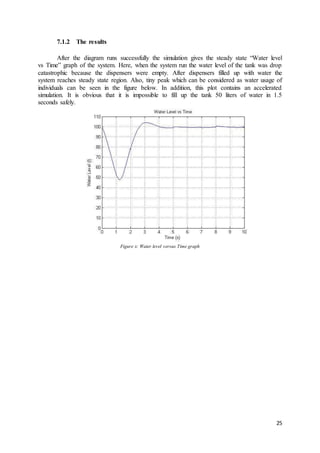
Downloaded 10 times

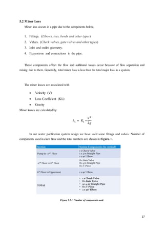
![3
2. LITERATURE SURVEY
Water treatment and purification methods are as significant as water itself. Therefore,
many institutions are constituted, many patents are invented or these issues become an
important topic for many scientific studies and researches.
2.1 Companies
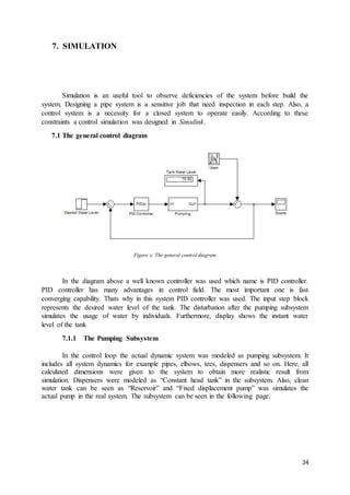
This section includes some companies which work for water purification, filtration and
human health.
Sartorius is a company that one of the world’s leading laboratory equipment providers.
They produces innovative products that helps customers to overcome in laboratory
environment. In our topic, Sartorius develop products according to customer needs. They can
produce laboratory water suppliers by type of source, by application or by system.
Sweet Water company is producing water treatment systems and under sink water
filters. Ecologist James P. McMahon develop suitable systems for commercial or household
systems.
National Sanitation Foundation (NSF) is an organization that works on public health
and safety. It has a professional staff of microbiologists, engineers, toxicologists, chemists
and so on. Also NSF laboratories provide a wide range of testing and certification about
human health.
PUR is a company that produce high technology filtration systems for consumers.
They develop faucet filters, pitchers & dispensers and replacement filters. Also PUR has NSF
certificate which means that their products are certified by National Sanitation Foundation
that highly recommended in public health and safety.
Amway is a worldwide company that produces many goods in different area. They
develop water purifiers for last users that has low cost and easy to install.
2.2 Patents
In this section, some patents are mentioned with respect to our project.
a) Reverse Osmosis Purification System – [US 6,190,558 B1 – Feb.20, 2001 – Robbins]
In this patent as shown in the Figure 2, reverse osmosis technique was used that
widespread and efficient. In the system, a motor driven pump supplies a feed stream to a
reverse osmosis unit resulting in the creation of a product water stream and concentrate or
brine stream. Also, the system has recirculation mode which sends the product water stream
to mixing unit and that results with producing more pure water.](https://image.slidesharecdn.com/thewaterpurifiers-finalreport-150518113704-lva1-app6891/85/Design-of-an-Automated-Central-Water-Filtering-System-Connected-to-Existing-Water-Dispensers-for-Yeditepe-University-Engineering-Floors-7-320.jpg)
![4
Figure 2.1: Reverse Osmosis Purification [1]
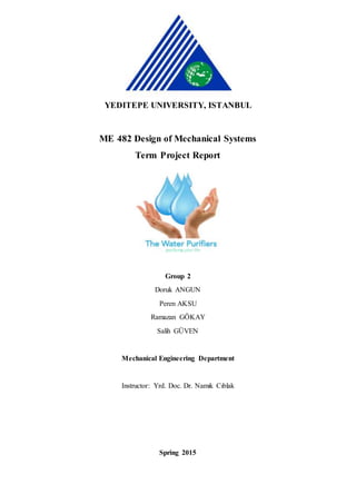
b) Drinking Water Purification Device - [US 2014/0008302 A1 – Jan.09, 2014 – King]
In this patent as shown in the Figure 3, a fast acting system was developed by the founder.
System contains silver ions that suitable for personal or household water containers. The
purification part contains a source of silver ions and a compound containing a hydantoin ring
that increased the presence of silver ions. Thereby, harmful microorganisms can be quickly
killed without any other addition.
Figure 2.2: Drinking Water Purification Device [2]](https://image.slidesharecdn.com/thewaterpurifiers-finalreport-150518113704-lva1-app6891/85/Design-of-an-Automated-Central-Water-Filtering-System-Connected-to-Existing-Water-Dispensers-for-Yeditepe-University-Engineering-Floors-8-320.jpg)
![5
c) Water Purification – [US 2014/0367344 A1 – Dec.18 2014 – Faure]
In this system as shown in the Figure 4, oxygen introduced water by the help of electrolysis of
the water. Then, that water treated with some ionized transition metal. The system prevents
growth of bacteria, fungal and viral pathogens in water. Also, it provides non-toxic method of
ensuring public health.
Figure 2.3: Water Purification [3]
d) Wireless Water Purification Systems and Wireless Remote Dispensing Devices For
Water Purification Systems – [US 7,824,543 B2 – Nov.02, 2010 – Larkner]
In this patent as shown in the Figure 5, a water purification system was equipped with a
wireless controller system. In this system, the main purification unit was connected with
remote dispensers by fluidly. Also, they have wireless transceivers that make communication
between purification unit and dispensers.
Figure 2.4: Wireless Water Purification [4]](https://image.slidesharecdn.com/thewaterpurifiers-finalreport-150518113704-lva1-app6891/85/Design-of-an-Automated-Central-Water-Filtering-System-Connected-to-Existing-Water-Dispensers-for-Yeditepe-University-Engineering-Floors-9-320.jpg)
![6
e) Water Purification Systems – [US 7,927,488 B1 – Apr.19, 2011 – Wilfong ]
In this system as shown Figure 6, the governing idea is utilizing oxidation. After oxidation,
the constituents can be removed by the help of a filter. Thus, impurities in the consuming
water can be removed easily. Also, this invention was balance the pH of the water by reduce
the hydronium ion concentration. Moreover, when pH increased the corrosivity of the water
reduced.
Figure 2.5: Water Purification System [5]
2.3 Scientific Studies
In this section, some scientific studies and academic research is mentioned. Up to now, a
scientific study has concerned about osmotic water purification system. Osmotic water purification
systems produces a clean sugar – electrolyte drink from almost any water source [6].
A study which was published at 2000 concerned about the cleanliness of the drinking
water. This study was conducted because in the beginning of the 2000’s, Canada’s drinking
water has become a very important subject because of the Escherichia coli infection in
Walkerton [7].
Another academic research was interested with household water purification system.
In household applications, people can use ceramic filters, chlorination with storage in an improved
vessel, solar disinfection and so on. However, each of these applications have limitation and the have
to be improve [8].
And another scientific study was about carbon nanotube membrane for water purification.
Water purification is a subject that works on nano size particles or infectives. Thereby,
nanotechnology is directly influence on water purification systems. As mentioned in the article, a
carbon nanotube membrane make the transport of water and antimicrobial properties faster [9].](https://image.slidesharecdn.com/thewaterpurifiers-finalreport-150518113704-lva1-app6891/85/Design-of-an-Automated-Central-Water-Filtering-System-Connected-to-Existing-Water-Dispensers-for-Yeditepe-University-Engineering-Floors-10-320.jpg)
![20
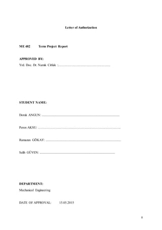
6. COST ANALYSIS
Total cost of this design consists of
1. Pipes and fittings
2. Valves
3. Filters
4. Pump
5. Control Unit
6. Water Tank
7. Design and engineering costs.
6.1 Cost of pipes and fittings
a) T-Piece
Figure 6.1: T-Piece fitting
Brand / Model Number= FIRAT / 7742252520 [10]
Unit Cost= 0.50 TL
Total Cost= 8 x 0.50 TL= 4 TL
b) 90° elbow
Figure 6.2: 90 degree elbow fitting
Brand / Model Number= FIRAT / 771000025[10]
Unit Cost= 0.40 TL
Total Cost= 2 x 0.40 TL= 0.80 TL](https://image.slidesharecdn.com/thewaterpurifiers-finalreport-150518113704-lva1-app6891/85/Design-of-an-Automated-Central-Water-Filtering-System-Connected-to-Existing-Water-Dispensers-for-Yeditepe-University-Engineering-Floors-24-320.jpg)
![21
c) Straight pipe
Figure 6.3: Straight pipe
Brand / Model Number= FIRAT / PPRC with fiberglass [10]
20 mm
Cost per meter= 2.99 TL
Total Cost=40 m x 2.99 TL= 119.6 TL
25 mm
Cost per meter= 4.34 TL
Total Cost=20 m x 4.34 TL= 86.8 TL
Total cost of straight pipe = 119.6 TL + 86.8 TL= 206.4 TL
6.2 Cost of valves:
a) Gate valves
Figure 6.2.1: Gate valve
Brand / Model Number= DUYAR / DIN 3216 [11]
Unit Cost= 10 TL
Total Cost= 8 x 10 TL= 80 TL](https://image.slidesharecdn.com/thewaterpurifiers-finalreport-150518113704-lva1-app6891/85/Design-of-an-Automated-Central-Water-Filtering-System-Connected-to-Existing-Water-Dispensers-for-Yeditepe-University-Engineering-Floors-25-320.jpg)
![22
b) Check valves
Figure 6.2.2: Check valve
Brand / Model Number= DUYAR / Disc Type Check Valve [11]
Unit Cost= 42 TL
Total Cost= 1 x 42 TL= 42 TL
6.3 Cost of Filter
Figure 6.3.1: Reverse osmosis filter
Reverse Osmosis filter is used in this design according to the election between design
alternatives.
Brand / Model Number= WATTS / R12-1200-1 Wall Mounted RO System [12]
Total Cost= 7830TL
6.4 Cost of pump
Figure 6.4.1: Pump](https://image.slidesharecdn.com/thewaterpurifiers-finalreport-150518113704-lva1-app6891/85/Design-of-an-Automated-Central-Water-Filtering-System-Connected-to-Existing-Water-Dispensers-for-Yeditepe-University-Engineering-Floors-26-320.jpg)
![23
Brand / Model Number= WILO / FMHI 405 1,1/2-M-1-E Multi Staged Horizontal Domestic
Hidrofor [13]
Total Cost=1.961 TL
6.5 Cost of control unit
Brand / Model Number= RGCONTROL UNIT / SG5221 Water Pump Controller
Total Cost= 175 TL
6.6 Cost of water tank
Figure 6.6.1: Water tank
Brand / Model Number= KARMOD/ Y 300 [14]
Total Cost= 500 TL
6.7 Designand engineering costs
Estimated cost of design and engineering cost is 10000 TL
According to these costs total cost to apply this design to Yeditepe University Engineering
floors is calculated as ;
𝑇𝑜𝑡𝑎𝑙 𝐶𝑜𝑠𝑡 = 10,000 + 7,830 + 1,961 + 500 + 206.4 + 171 + 80 + 42 + 4 + 0.80 = 𝟐𝟎, 𝟕𝟗𝟓 𝑻𝑳](https://image.slidesharecdn.com/thewaterpurifiers-finalreport-150518113704-lva1-app6891/85/Design-of-an-Automated-Central-Water-Filtering-System-Connected-to-Existing-Water-Dispensers-for-Yeditepe-University-Engineering-Floors-27-320.jpg)
![27
9. REFERENCES
[1] Robbins, Adam. "Reverse osmosis purification system." U.S. Patent No.
6,190,558. 20 Feb. 2001.
[2] King, Joseph. "Drinking Water Purification Device." U.S. Patent No.
2014/0008302 A1. 09 Jan. 2014.
[3] Faure, Frederick Jacobus. "Water Purification." U.S. Patent No. 2014/0367344 A1.
18 Dec. 2014.
[4] Larkner, Thomas Joseph. "Wireless water purification systems and wireless remote
dispensing devices for water purification systems." U.S. Patent No. 7,824,543. 2 Nov.
2010.
[5] Wilfong, Rudy B. "Water purification systems." U.S. Patent No. 7,927,488. 19
Apr. 2011.
[6] ‘’Point of use water treatment with forward osmosis for emergency relief’’-Ethan
Butler, Andrew Silva, Kyle Horton, Zachary Rom, Malgorzata Chwatko, Arie
Havasov, Jeffrey R. McCutcheon.
[7] "Making Our Water Safe to Drink "- Weir, Erica. Canadian Medical Association
Journal (2000).
[8] "Household water purification: Low-cost interventions."Agrawal, V. K., and R.
Bhalwar. Medical Journal Armed Forces India 65.3 (2009): 260-263.
[9] ‘’High performance and antifouling vertically aligned carbon nanotube membrane
forwater purification’’ - YoungbinBaek , CholinKim , DongKyunSeo , TaewooKim ,
JeongSeokLee , YongHyupKim , KyungHyunAhn , SangSeekBae , SangCheolLee ,
Jaelim Lim , KyunghyukLee , JeyongYoon
[10] http://www.firat.com/userfiles/file/pdf/tr/Brosurler2014/PPRC-
KOMPOZIT_TR_2014.pdf
[11] http://www.duyarvana.com/
[12] http://www.belkraft.com/images/R12.jpg
[13] http://www.wiloturkiye.com/FMHI-405-112-M-1-E-Monofaze-Cok-Kademeli-
Yatay-Hidromatli-Hidrofor%2cPR-264.html
[14] http://www.karmod.com](https://image.slidesharecdn.com/thewaterpurifiers-finalreport-150518113704-lva1-app6891/85/Design-of-an-Automated-Central-Water-Filtering-System-Connected-to-Existing-Water-Dispensers-for-Yeditepe-University-Engineering-Floors-31-320.jpg)

This document is a term project report submitted by a group of 4 mechanical engineering students at Yeditepe University in Istanbul for their ME 482 Design of Mechanical Systems course. The project involves designing an automated central water filtering system connected to existing water dispensers in the engineering building. The report includes sections on literature review of relevant companies and patents, preliminary design alternatives considered, selection of final designs, calculations of head losses and flow rates, and conclusions. The goal of the project is to address issues with the current discrete water supply system using large water bottles by implementing a continuous supply system with centralized filtering and distribution to dispensers on each floor.