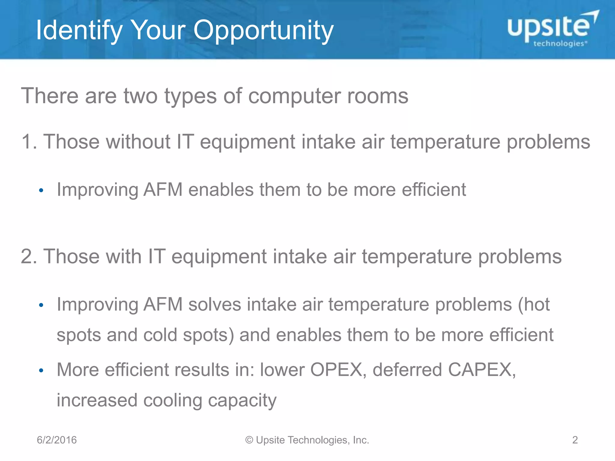
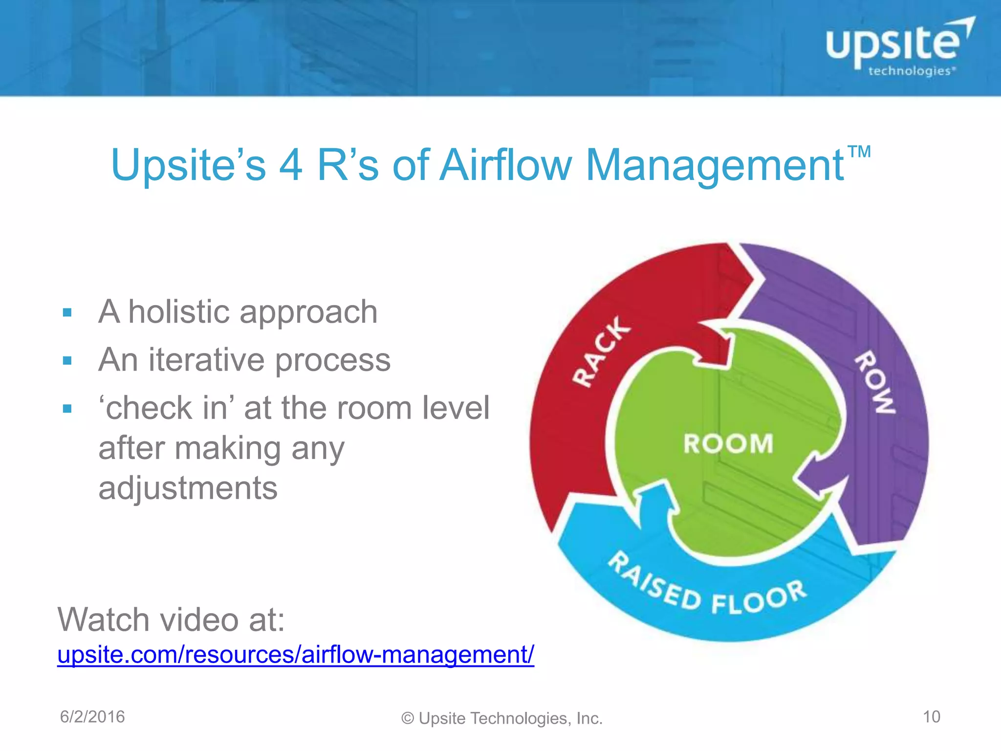
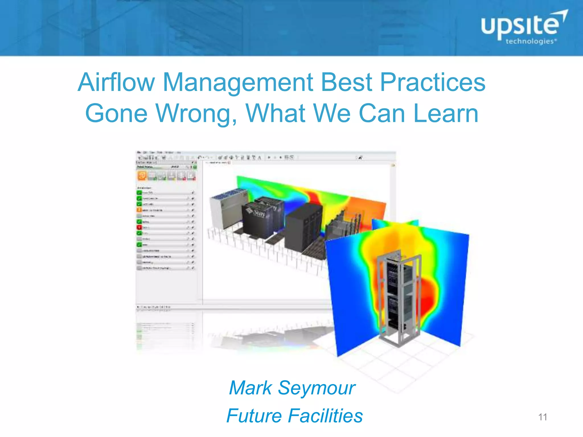
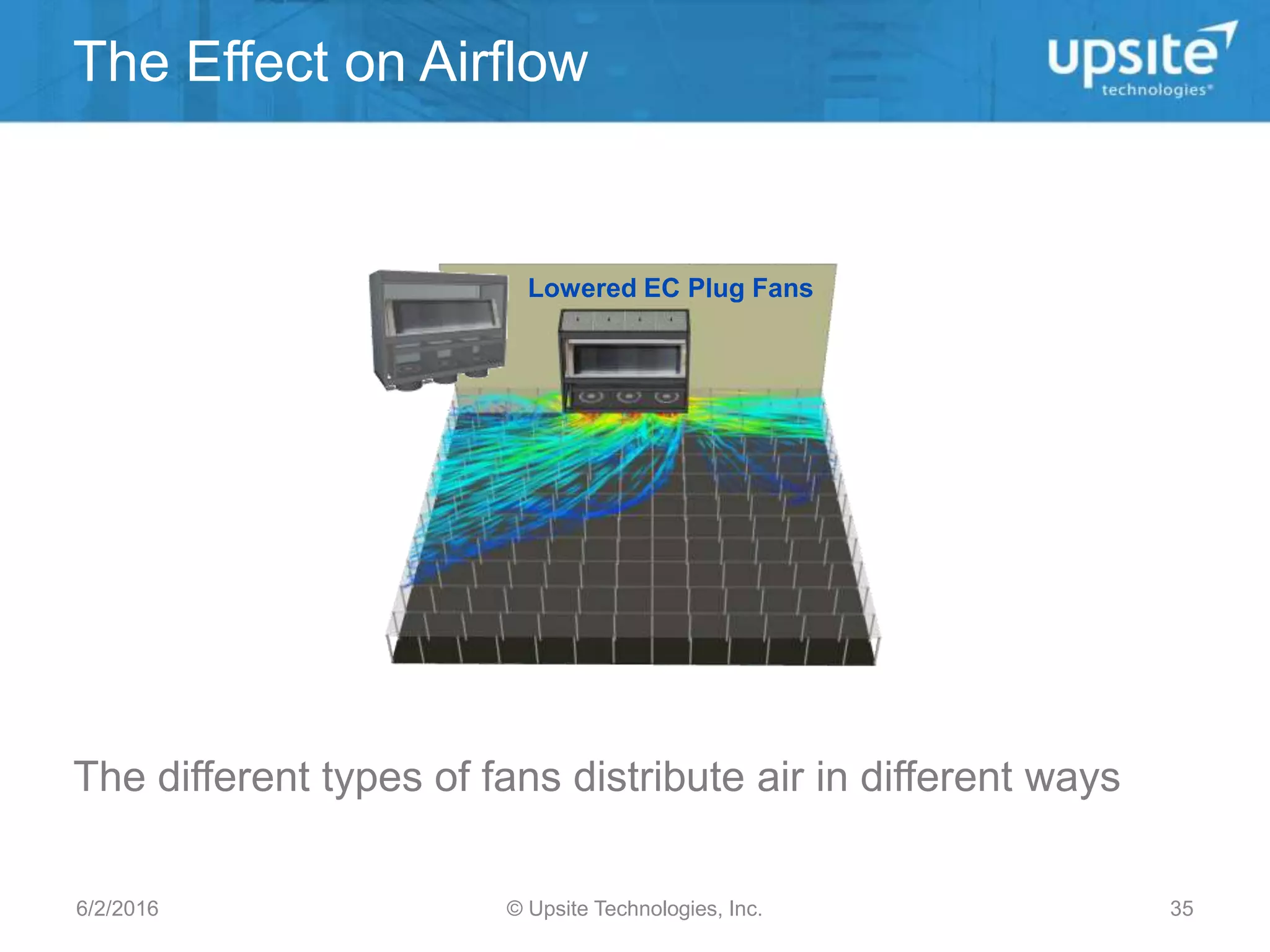
The Science Behind Airflow
Management Best Practices
Lars Strong, P.E., Upsite Technologies
Mark Seymour, Future Facilities
Airflow Management Awareness Month
June 1, 2016
Identify Your Opportunity
© Upsite Technologies, Inc.6/2/2016 2
There are two types of computer rooms
1. Those without IT equipment intake air temperature problems
• Improving AFM enables them to be more efficient
2. Those with IT equipment intake air temperature problems
• Improving AFM solves intake air temperature problems (hot
spots and cold spots) and enables them to be more efficient
• More efficient results in: lower OPEX, deferred CAPEX,
increased cooling capacity
Why Airflow Management
© Upsite Technologies, Inc.6/2/2016 3
Total Load
IT Load
PUE =
Mechanical plant +
cooling fans: 35%
of total load, 73%
of non IT Load
BYPASS AIRFLOW CLARIFIED
© Upsite Technologies, Inc.6/2/2016 4
Definition of Bypass Airflow
Any cooling air that does not pass through IT
equipment before returning to a cooling unit
Bypass flow rate (CFM) = total cooling supply
flow rate (CFM) – total IT equipment flow rate
(CFM)
© Upsite Technologies, Inc.
ΔT Through IT Equipment
UPS load (kW) x avg CFM/kW = Total IT CFM
IT Equipment Required Flow Rate
IT
Equipment
Delta T
(deg F)
15° 20° 25° 30° 35° 40°
Required
flow rate
(CFM/kW)
211 158 126 105 90 79
© Upsite Technologies, Inc.
Bypass Airflow Clarified
Typical existing conditions
© Upsite Technologies, Inc.
Bypass Airflow Clarified
After AFM improvements
© Upsite Technologies, Inc.
Bypass Airflow Clarified
Optimized
© Upsite Technologies, Inc.
Upsite’s 4 R’s of Airflow Management™
 A holistic approach
 An iterative process
 ‘check in’ at the room level
after making any
adjustments
6/2/2016 10
Watch video at:
upsite.com/resources/airflow-management/
© Upsite Technologies, Inc.
Airflow Management Best Practices
Gone Wrong, What We Can Learn
Mark Seymour
Future Facilities 11
This presentation illustrates some of the classic actions in a
data center that can create airflow management issues
The intent is to reveal:
• Why considering airflow is important
• That good practice is just that – it’s not a guarantee
• Engineering simulation is used to illustrate airflow that is
otherwise unseen and enabling proactive operational
management
• Airflow management applies to both the rack/cabinet level
and the room level
Introduction
© Upsite Technologies, Inc.6/2/2016 12
futurefacilities.co
m
Energy efficiency of the
cooling system can be
undermined by
• Negative flow 
o Often through perforated tiles
near the cooling unit
• By-pass
o Can overshoot IT or pass
through unmanaged leakage.
E.g. cable penetrations
• Recirculation 
o Occurs in the rack as well as
the room is important
Common issues
© Upsite Technologies, Inc.6/2/2016 13
CABLE PENETRATIONS & LEAKAGE
© Upsite Technologies, Inc.6/2/2016 14
futurefacilities.co
m
 Unmanaged cable
penetrations
 Typically installed in
raised floor in rear if the
cabinet
 Installing cable
management is an easy
win but care should be
taken to ensure the
cooling is not in use
Leakage Paths
 Watch for leakage paths
• Under the cabinet
• Over the cabinet (through
containment)
• Between cabinets
• End of rows (through
containment)
• Through Cooling Units on
standby
• Similarly in the rack
o Under
o Over
o Between
o Around equipment
o Through IT equipment that is
off
© Upsite Technologies, Inc.6/2/2016 15
futurefacilities.co
m
Cable Penetration Seals
Cable Penetration Management
 Why practice it?
• Stop air leaking out of the
cable penetrations
• Increase the pressure in
the raised floor plenum
• Stop bypass cooling down
the hot return air
• Force more air out of the
perforated tiles and grates
in front of the IT
equipment
© Upsite Technologies, Inc.6/2/2016 16
futurefacilities.co
m
 Hot Aisle / Cold
Aisle
 Mix of Equipment
 Size: 1,066 sq. ft.
 Cooling: 55.6 tons
(196 kW)
 Load: 152 kW
Example Room
© Upsite Technologies, Inc.6/2/2016 17
futurefacilities.co
m
ASHRAE Temperature Compliance
One rack has inlet temperatures above the ASHRAE
Temperature Compliance recommended range
© Upsite Technologies, Inc.6/2/2016 18
Using simulation we can investigate the impact of adding
brush seals to the cable penetrations:
Modeling of Penetration Seals
© Upsite Technologies, Inc.6/2/2016 19
futurefacilities.co
m
Static Pressure
© Upsite Technologies, Inc.6/2/2016 20
futurefacilities.co
m
Perforated Tile Flow
© Upsite Technologies, Inc.6/2/2016 21
futurefacilities.co
m
ASHRAE Temperature Results
Comparison
© Upsite Technologies, Inc.6/2/2016 22
Improving raised floor open area
management reveals need to improve
rack airflow management
futurefacilities.co
m
Why Did the Room Get Worse?
With Brush
Seals
No Seals
Improving rack airflow management with blanking
panels, rail seals, and under rack panels will bring IT
intake air temperatures back into compliance
© Upsite Technologies, Inc.6/2/2016 23
futurefacilities.co
m
 Sealing holes in the floor are still the best practice
 It is critical to apply best practices to sealing the
cabinet at the same time.
 Final engineering simulation image would reveal
optimized cooling with no exhaust air recirculation
6/2/2016 © Upsite Technologies, Inc. 24
futurefacilities.co
m
Equipment Configuration
Consider a cabinet housing
a blade system and 3 1U
servers
• Does it matter how the 2
equipment types are
installed in this cabinet?
• Option 1 – Three 1U
servers placed on top of a
BladeCenter H
3kW Blade
Enclosure
3 x 1U 275W
Servers
15o
C / 59°F Supply Air
© Upsite Technologies, Inc.6/2/2016 25
futurefacilities.co
m
Equipment Configuration
Base Configuration – Option 1
Recirculation
under cabinet
Maximum inlet temperature
o
C (°F)
Blade 27.1 (80.8)
Server1 19.6 (67.3)
Server2 19.7 (67.5)
Server3 18.9 (66.0)
© Upsite Technologies, Inc.6/2/2016 26
futurefacilities.co
m
Equipment Configuration
Option: 1U servers under blade
Maximum inlet temperature
o
C (°F)
Blade 18.1 (64.6)
Server1 19.1 (66.4)
Server2 20.9 (69.6)
Server3 21.8 (71.2)
Recirculation from
1u servers is cooler
Recirculation of this nature can occur
whether or not the data center is
contained. The solution is blocking the
under rack airflow.
© Upsite Technologies, Inc.
6/2/2016 27
AISLE CONTAINMENT
© Upsite Technologies, Inc.6/2/2016 28
futurefacilities.co
m
Consider two rows of equipment with full cold aisle
containment:
Cold Aisle Containment
© Upsite Technologies, Inc.6/2/2016 29
futurefacilities.co
m
Containment Measured
Warmer Air
Supply
No change
Colder Air
Supply
© Upsite Technologies, Inc.6/2/2016 30
futurefacilities.co
m
 Simulation shows what is
happening:
• There is a lack of available
airflow
• Uncontained, the
additional air required
recirculates via the room
over the top of the
cabinets. Consequently it
mixes and so is colder
than the air in the hot aisle
• Contained, the additional
air recirculates directly
from the back of the
cabinets and, without any
mixing, it is hotter.
Simulation Explains All
Uncontained
Contained
© Upsite Technologies, Inc.6/2/2016 31
COOLING UNITS
© Upsite Technologies, Inc.6/2/2016 32
futurefacilities.co
m
 More efficient (up to 30%)
 Easily controlled (0-10V
signal)
 Longer life and reduced
maintenance
 Improved airflow through
the CRAC/CRAH
 Reduced noise
Benefits of EC fans?
© Upsite Technologies, Inc.6/2/2016 33
futurefacilities.co
m
Air Distribution
EC Plug Fans vs Traditional Blowers
Blower
© Upsite Technologies, Inc.6/2/2016 34
Traditional BlowersLowered EC Plug Fans
The different types of fans distribute air in different ways
The Effect on Airflow
© Upsite Technologies, Inc.6/2/2016 35
futurefacilities.co
m
 6,727ft² of floor space
 200+ Cabinets
 800kW Cooling Capacity at
N+2
Test Facility
© Upsite Technologies, Inc.6/2/2016 36
 Airflow distribution patterns look very different.
 How has this affected the available cooling?
Grille Flow
© Upsite Technologies, Inc.6/2/2016 37
0
10
20
30
40
50
60
70
80
90
100
1 2 3 4 5 6 7 8 9 10 11 12 13
PotentialCooling(kW)
Cold Aisle
Cooling Available per Row
© Upsite Technologies, Inc.6/2/2016 38
Reduced cooling capacity puts IT at risk of thermal
shutdown
Immediate Issues
Aisle 4 cooling
reduced 21kW
64 Blades now at
risk
Aisle 5 cooling
reduced 15kW
30 Proliants now at
risk
© Upsite Technologies, Inc.6/2/2016 39
Immediate Issues
© Upsite Technologies, Inc.6/2/2016 40
Upsite's 4 R's of Airflow Optimization provide a guide for
implement changes and achieving the greatest benefits in
your data center.
“Efficiency can’t be purchased,
it has to be managed”
Julian Kudritzki
- The Uptime Institute
 Airflow management is essential for optimizing capacity
and efficiency of the entire data center
 Good practices are often beneficial but should be
undertaken with due diligence
 Airflow is invisible, therefore the hardest thing to manage
in a data center
 Actions for one scenario may be beneficial while in
another counter productive – e.g. total containment in an
over-provisioned scenario compared with an under-
provisioned scenario.
 Engineering simulation can visualize and help guide
airflow management choices
 Apply the 4 R’s Methodology to Airflow Management
Summary & Conclusions
© Upsite Technologies, Inc.6/2/2016 41
 June 8: 5 Myths of Data Center Containment
Presented by Lars Strong, P.E.
 June 15: How IT Decisions Impact Facilities: The
Importance of Mutual Understanding
Presented by Ian Seaton and Lars Strong, P.E.
 June 22: The 4 Delta T’s of Airflow Management
Presented by Lars Strong, P.E.
 Register at upsite.com/airflow-management-awareness-
month
Upcoming Schedule
© Upsite Technologies, Inc.6/2/2016 42
Thank you!
@UpsiteTech
blog.upsite.com
On LinkedIn
Lars Strong, P.E.
Senior Engineer, Upsite
Technologies
lstrong@upsite.com
Follow Upsite for the latest
news and information on
data center AFM.
Mark Seymour
Senior Engineer, Future
Facilities
Mark.Seymour@futurefacilities.com

The Science Behind Airflow Management Best Practices

  • 1.
    The Science BehindAirflow Management Best Practices Lars Strong, P.E., Upsite Technologies Mark Seymour, Future Facilities Airflow Management Awareness Month June 1, 2016
  • 2.
    Identify Your Opportunity ©Upsite Technologies, Inc.6/2/2016 2 There are two types of computer rooms 1. Those without IT equipment intake air temperature problems • Improving AFM enables them to be more efficient 2. Those with IT equipment intake air temperature problems • Improving AFM solves intake air temperature problems (hot spots and cold spots) and enables them to be more efficient • More efficient results in: lower OPEX, deferred CAPEX, increased cooling capacity
  • 3.
    Why Airflow Management ©Upsite Technologies, Inc.6/2/2016 3 Total Load IT Load PUE = Mechanical plant + cooling fans: 35% of total load, 73% of non IT Load
  • 4.
    BYPASS AIRFLOW CLARIFIED ©Upsite Technologies, Inc.6/2/2016 4
  • 5.
    Definition of BypassAirflow Any cooling air that does not pass through IT equipment before returning to a cooling unit Bypass flow rate (CFM) = total cooling supply flow rate (CFM) – total IT equipment flow rate (CFM) © Upsite Technologies, Inc.
  • 6.
    ΔT Through ITEquipment UPS load (kW) x avg CFM/kW = Total IT CFM IT Equipment Required Flow Rate IT Equipment Delta T (deg F) 15° 20° 25° 30° 35° 40° Required flow rate (CFM/kW) 211 158 126 105 90 79 © Upsite Technologies, Inc.
  • 7.
    Bypass Airflow Clarified Typicalexisting conditions © Upsite Technologies, Inc.
  • 8.
    Bypass Airflow Clarified AfterAFM improvements © Upsite Technologies, Inc.
  • 9.
    Bypass Airflow Clarified Optimized ©Upsite Technologies, Inc.
  • 10.
    Upsite’s 4 R’sof Airflow Management™  A holistic approach  An iterative process  ‘check in’ at the room level after making any adjustments 6/2/2016 10 Watch video at: upsite.com/resources/airflow-management/ © Upsite Technologies, Inc.
  • 11.
    Airflow Management BestPractices Gone Wrong, What We Can Learn Mark Seymour Future Facilities 11
  • 12.
    This presentation illustratessome of the classic actions in a data center that can create airflow management issues The intent is to reveal: • Why considering airflow is important • That good practice is just that – it’s not a guarantee • Engineering simulation is used to illustrate airflow that is otherwise unseen and enabling proactive operational management • Airflow management applies to both the rack/cabinet level and the room level Introduction © Upsite Technologies, Inc.6/2/2016 12
  • 13.
    futurefacilities.co m Energy efficiency ofthe cooling system can be undermined by • Negative flow  o Often through perforated tiles near the cooling unit • By-pass o Can overshoot IT or pass through unmanaged leakage. E.g. cable penetrations • Recirculation  o Occurs in the rack as well as the room is important Common issues © Upsite Technologies, Inc.6/2/2016 13
  • 14.
    CABLE PENETRATIONS &LEAKAGE © Upsite Technologies, Inc.6/2/2016 14
  • 15.
    futurefacilities.co m  Unmanaged cable penetrations Typically installed in raised floor in rear if the cabinet  Installing cable management is an easy win but care should be taken to ensure the cooling is not in use Leakage Paths  Watch for leakage paths • Under the cabinet • Over the cabinet (through containment) • Between cabinets • End of rows (through containment) • Through Cooling Units on standby • Similarly in the rack o Under o Over o Between o Around equipment o Through IT equipment that is off © Upsite Technologies, Inc.6/2/2016 15
  • 16.
    futurefacilities.co m Cable Penetration Seals CablePenetration Management  Why practice it? • Stop air leaking out of the cable penetrations • Increase the pressure in the raised floor plenum • Stop bypass cooling down the hot return air • Force more air out of the perforated tiles and grates in front of the IT equipment © Upsite Technologies, Inc.6/2/2016 16
  • 17.
    futurefacilities.co m  Hot Aisle/ Cold Aisle  Mix of Equipment  Size: 1,066 sq. ft.  Cooling: 55.6 tons (196 kW)  Load: 152 kW Example Room © Upsite Technologies, Inc.6/2/2016 17
  • 18.
    futurefacilities.co m ASHRAE Temperature Compliance Onerack has inlet temperatures above the ASHRAE Temperature Compliance recommended range © Upsite Technologies, Inc.6/2/2016 18
  • 19.
    Using simulation wecan investigate the impact of adding brush seals to the cable penetrations: Modeling of Penetration Seals © Upsite Technologies, Inc.6/2/2016 19
  • 20.
  • 21.
    futurefacilities.co m Perforated Tile Flow ©Upsite Technologies, Inc.6/2/2016 21
  • 22.
    futurefacilities.co m ASHRAE Temperature Results Comparison ©Upsite Technologies, Inc.6/2/2016 22 Improving raised floor open area management reveals need to improve rack airflow management
  • 23.
    futurefacilities.co m Why Did theRoom Get Worse? With Brush Seals No Seals Improving rack airflow management with blanking panels, rail seals, and under rack panels will bring IT intake air temperatures back into compliance © Upsite Technologies, Inc.6/2/2016 23
  • 24.
    futurefacilities.co m  Sealing holesin the floor are still the best practice  It is critical to apply best practices to sealing the cabinet at the same time.  Final engineering simulation image would reveal optimized cooling with no exhaust air recirculation 6/2/2016 © Upsite Technologies, Inc. 24
  • 25.
    futurefacilities.co m Equipment Configuration Consider acabinet housing a blade system and 3 1U servers • Does it matter how the 2 equipment types are installed in this cabinet? • Option 1 – Three 1U servers placed on top of a BladeCenter H 3kW Blade Enclosure 3 x 1U 275W Servers 15o C / 59°F Supply Air © Upsite Technologies, Inc.6/2/2016 25
  • 26.
    futurefacilities.co m Equipment Configuration Base Configuration– Option 1 Recirculation under cabinet Maximum inlet temperature o C (°F) Blade 27.1 (80.8) Server1 19.6 (67.3) Server2 19.7 (67.5) Server3 18.9 (66.0) © Upsite Technologies, Inc.6/2/2016 26
  • 27.
    futurefacilities.co m Equipment Configuration Option: 1Uservers under blade Maximum inlet temperature o C (°F) Blade 18.1 (64.6) Server1 19.1 (66.4) Server2 20.9 (69.6) Server3 21.8 (71.2) Recirculation from 1u servers is cooler Recirculation of this nature can occur whether or not the data center is contained. The solution is blocking the under rack airflow. © Upsite Technologies, Inc. 6/2/2016 27
  • 28.
    AISLE CONTAINMENT © UpsiteTechnologies, Inc.6/2/2016 28
  • 29.
    futurefacilities.co m Consider two rowsof equipment with full cold aisle containment: Cold Aisle Containment © Upsite Technologies, Inc.6/2/2016 29
  • 30.
    futurefacilities.co m Containment Measured Warmer Air Supply Nochange Colder Air Supply © Upsite Technologies, Inc.6/2/2016 30
  • 31.
    futurefacilities.co m  Simulation showswhat is happening: • There is a lack of available airflow • Uncontained, the additional air required recirculates via the room over the top of the cabinets. Consequently it mixes and so is colder than the air in the hot aisle • Contained, the additional air recirculates directly from the back of the cabinets and, without any mixing, it is hotter. Simulation Explains All Uncontained Contained © Upsite Technologies, Inc.6/2/2016 31
  • 32.
    COOLING UNITS © UpsiteTechnologies, Inc.6/2/2016 32
  • 33.
    futurefacilities.co m  More efficient(up to 30%)  Easily controlled (0-10V signal)  Longer life and reduced maintenance  Improved airflow through the CRAC/CRAH  Reduced noise Benefits of EC fans? © Upsite Technologies, Inc.6/2/2016 33
  • 34.
    futurefacilities.co m Air Distribution EC PlugFans vs Traditional Blowers Blower © Upsite Technologies, Inc.6/2/2016 34
  • 35.
    Traditional BlowersLowered ECPlug Fans The different types of fans distribute air in different ways The Effect on Airflow © Upsite Technologies, Inc.6/2/2016 35
  • 36.
    futurefacilities.co m  6,727ft² offloor space  200+ Cabinets  800kW Cooling Capacity at N+2 Test Facility © Upsite Technologies, Inc.6/2/2016 36
  • 37.
     Airflow distributionpatterns look very different.  How has this affected the available cooling? Grille Flow © Upsite Technologies, Inc.6/2/2016 37
  • 38.
    0 10 20 30 40 50 60 70 80 90 100 1 2 34 5 6 7 8 9 10 11 12 13 PotentialCooling(kW) Cold Aisle Cooling Available per Row © Upsite Technologies, Inc.6/2/2016 38
  • 39.
    Reduced cooling capacityputs IT at risk of thermal shutdown Immediate Issues Aisle 4 cooling reduced 21kW 64 Blades now at risk Aisle 5 cooling reduced 15kW 30 Proliants now at risk © Upsite Technologies, Inc.6/2/2016 39
  • 40.
    Immediate Issues © UpsiteTechnologies, Inc.6/2/2016 40 Upsite's 4 R's of Airflow Optimization provide a guide for implement changes and achieving the greatest benefits in your data center. “Efficiency can’t be purchased, it has to be managed” Julian Kudritzki - The Uptime Institute
  • 41.
     Airflow managementis essential for optimizing capacity and efficiency of the entire data center  Good practices are often beneficial but should be undertaken with due diligence  Airflow is invisible, therefore the hardest thing to manage in a data center  Actions for one scenario may be beneficial while in another counter productive – e.g. total containment in an over-provisioned scenario compared with an under- provisioned scenario.  Engineering simulation can visualize and help guide airflow management choices  Apply the 4 R’s Methodology to Airflow Management Summary & Conclusions © Upsite Technologies, Inc.6/2/2016 41
  • 42.
     June 8:5 Myths of Data Center Containment Presented by Lars Strong, P.E.  June 15: How IT Decisions Impact Facilities: The Importance of Mutual Understanding Presented by Ian Seaton and Lars Strong, P.E.  June 22: The 4 Delta T’s of Airflow Management Presented by Lars Strong, P.E.  Register at upsite.com/airflow-management-awareness- month Upcoming Schedule © Upsite Technologies, Inc.6/2/2016 42
  • 43.
    Thank you! @UpsiteTech blog.upsite.com On LinkedIn LarsStrong, P.E. Senior Engineer, Upsite Technologies lstrong@upsite.com Follow Upsite for the latest news and information on data center AFM. Mark Seymour Senior Engineer, Future Facilities Mark.Seymour@futurefacilities.com