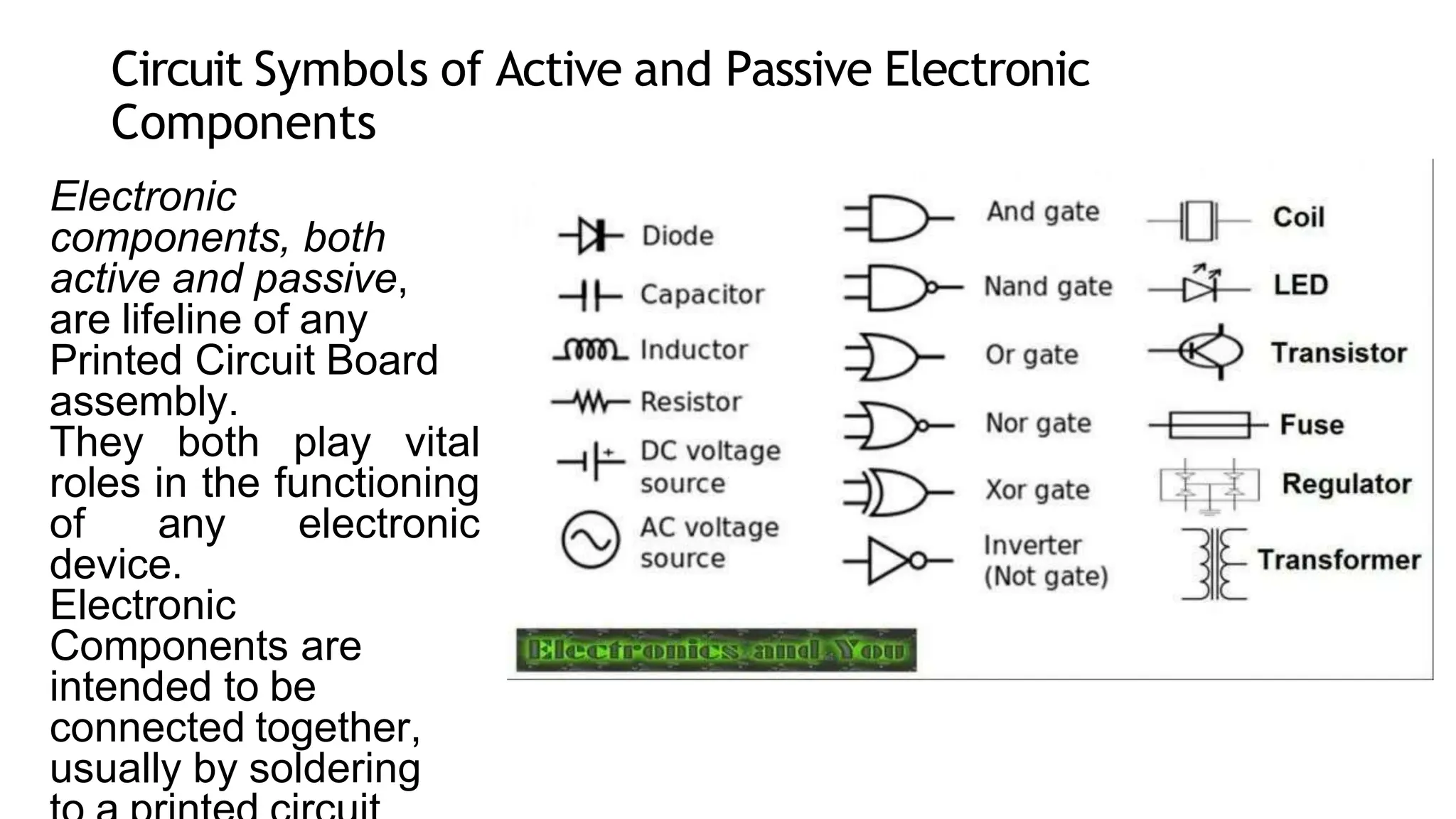
Testing Strategiesfor
Electronic Components
ALDRINE Y. TELERON
What are Passive Electronic
Components?
Passive electronic
components are those
that don’t have the ability
to control electric current
by means of another
electrical signal.
Examples of passive
electronic components
are
capacitors, resistors,
inductors, transformers, and
Circuit Symbols of Active and Passive Electronic
Components
Electronic
components, both
active and passive,
are lifeline of any
Printed Circuit Board
assembly.
They both play vital
roles in the functioning
of any electronic
device.
Electronic
Components are
intended to be
connected together,
usually by soldering
Dynamic Testing
• Electronics tests place a wide range of performance demands
on test equipment for static and dynamic test equipment.
The equipment is used to validate new designs, improve
manufacturing processes and prove the quality of end
products. Mechanical testing requirements involve static,
dynamic and fatigue testing in tensile, compression, shear
test modes.
• Testing the mechanical endurance and integrity of electronics
components and assemblies is important to validate designs,
improve manufacturing, and ensure the reliability of final
products.
In-Circuit Testing
In circuit test equipment provides a useful and efficient form
of printed circuit board test by measuring each component in turn
to check that it is in place and of the correct value. As most faults
on a board arise out of the manufacturing process and usually
consist of short circuits, open circuits or wrong components, this
form of testing catches most of the problems on a board. These
can easily be checked using simple measurements or resistance,
capacitance, and sometimes inductance between two points on
the circuit board.
In-circuit test equipment consists of a number of elements:
a.In circuit tester: The in circuit test system consists of a matrix of
drivers and sensors that are used to set up and perform the
measurements. There may be 1000 or more of these driver sensor
points. These are normally taken to a large connector conveniently
located on the system
b. Fixture: The in-circuit test system connector interfaces with the
second part of the tester - the fixture. In view of the variety of boards
this will be designed specifically for a particular board, and acts as
an interface between the board and the in circuit tester. It takes the
connections for the driver sensor points and routes them directly to
the relevant points on the board using a "bed of nails".
c.Software : Software is written for each board type that can be
tested. It instructs the test system what tests to perform, between
what points and details of the pass / fail criteria.
testingstrategiesforelectroniccomponents-191101072253.pptx

testingstrategiesforelectroniccomponents-191101072253.pptx

  • 1.
  • 2.
    What are PassiveElectronic Components? Passive electronic components are those that don’t have the ability to control electric current by means of another electrical signal. Examples of passive electronic components are capacitors, resistors, inductors, transformers, and
  • 3.
    Circuit Symbols ofActive and Passive Electronic Components Electronic components, both active and passive, are lifeline of any Printed Circuit Board assembly. They both play vital roles in the functioning of any electronic device. Electronic Components are intended to be connected together, usually by soldering
  • 4.
    Dynamic Testing • Electronicstests place a wide range of performance demands on test equipment for static and dynamic test equipment. The equipment is used to validate new designs, improve manufacturing processes and prove the quality of end products. Mechanical testing requirements involve static, dynamic and fatigue testing in tensile, compression, shear test modes. • Testing the mechanical endurance and integrity of electronics components and assemblies is important to validate designs, improve manufacturing, and ensure the reliability of final products.
  • 6.
    In-Circuit Testing In circuittest equipment provides a useful and efficient form of printed circuit board test by measuring each component in turn to check that it is in place and of the correct value. As most faults on a board arise out of the manufacturing process and usually consist of short circuits, open circuits or wrong components, this form of testing catches most of the problems on a board. These can easily be checked using simple measurements or resistance, capacitance, and sometimes inductance between two points on the circuit board.
  • 7.
    In-circuit test equipmentconsists of a number of elements: a.In circuit tester: The in circuit test system consists of a matrix of drivers and sensors that are used to set up and perform the measurements. There may be 1000 or more of these driver sensor points. These are normally taken to a large connector conveniently located on the system b. Fixture: The in-circuit test system connector interfaces with the second part of the tester - the fixture. In view of the variety of boards this will be designed specifically for a particular board, and acts as an interface between the board and the in circuit tester. It takes the connections for the driver sensor points and routes them directly to the relevant points on the board using a "bed of nails". c.Software : Software is written for each board type that can be tested. It instructs the test system what tests to perform, between what points and details of the pass / fail criteria.