Download to read offline
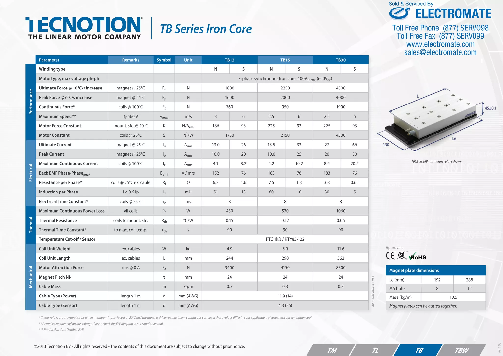
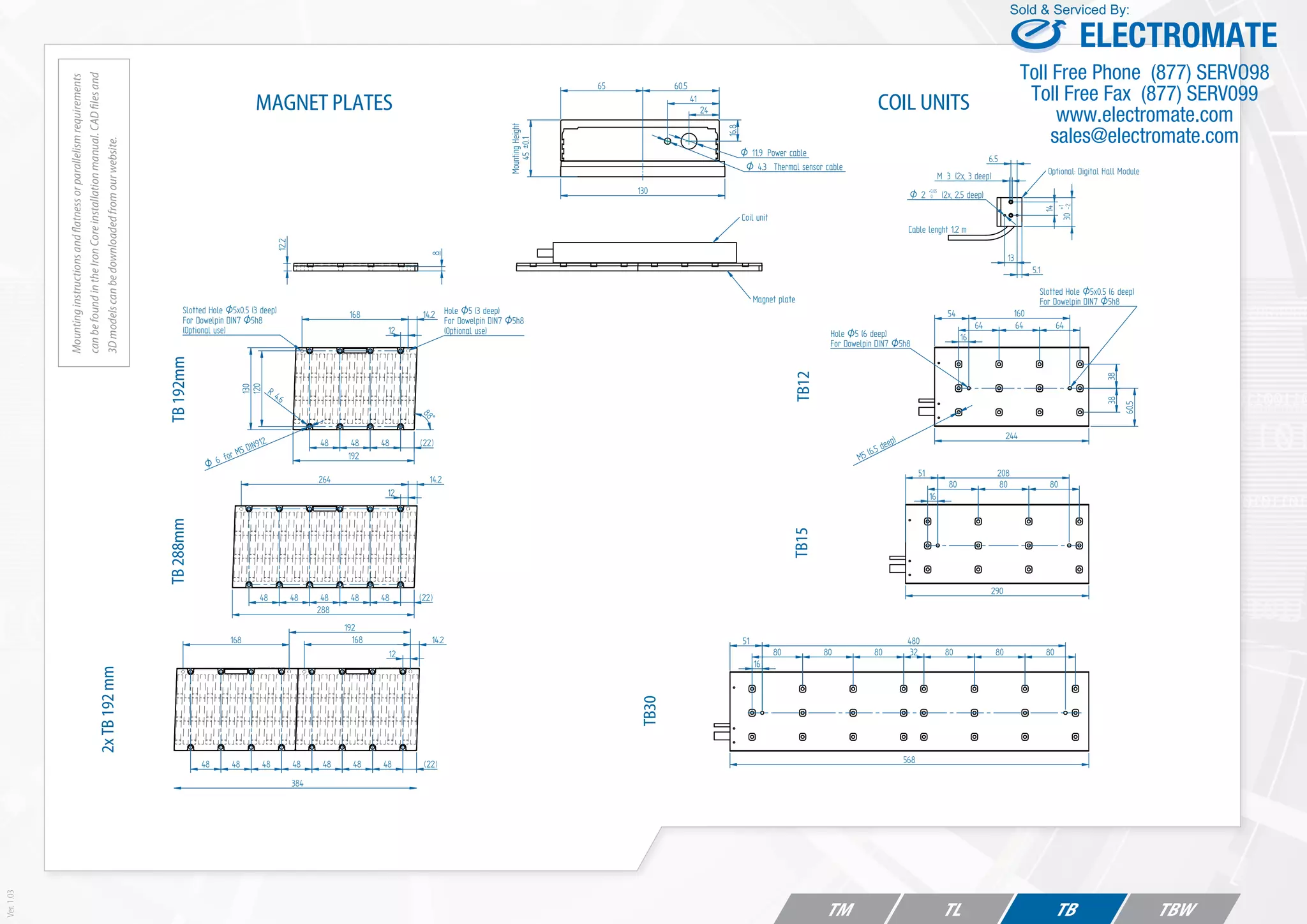

This document provides specifications for three tubular linear motor models: the TB12, TB15, and TB30. It includes performance data like maximum force, speed, and current as well as electrical properties and mechanical dimensions. Mounting instructions and CAD files can be found online or in the installation manual.


