This document provides information about a system programming course at Vidyavahini First Grade College. It includes:
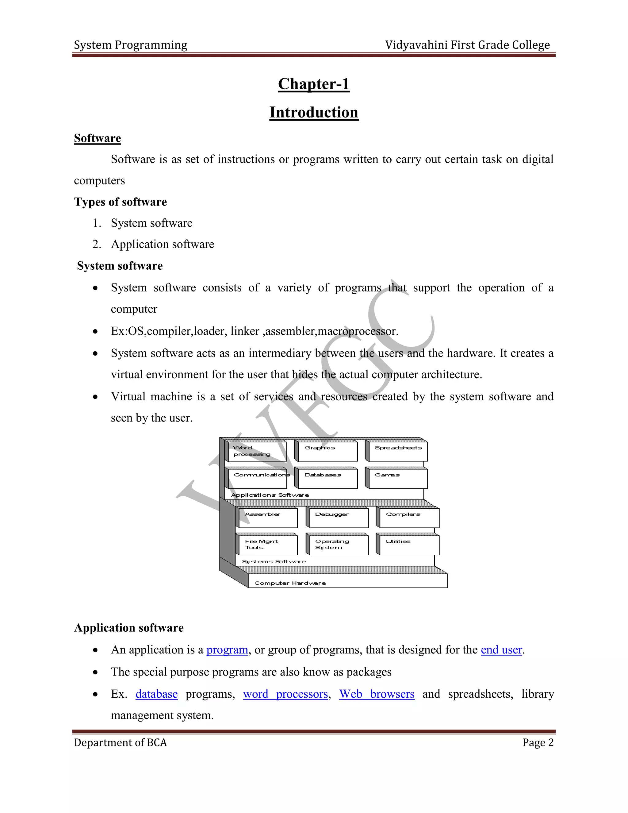
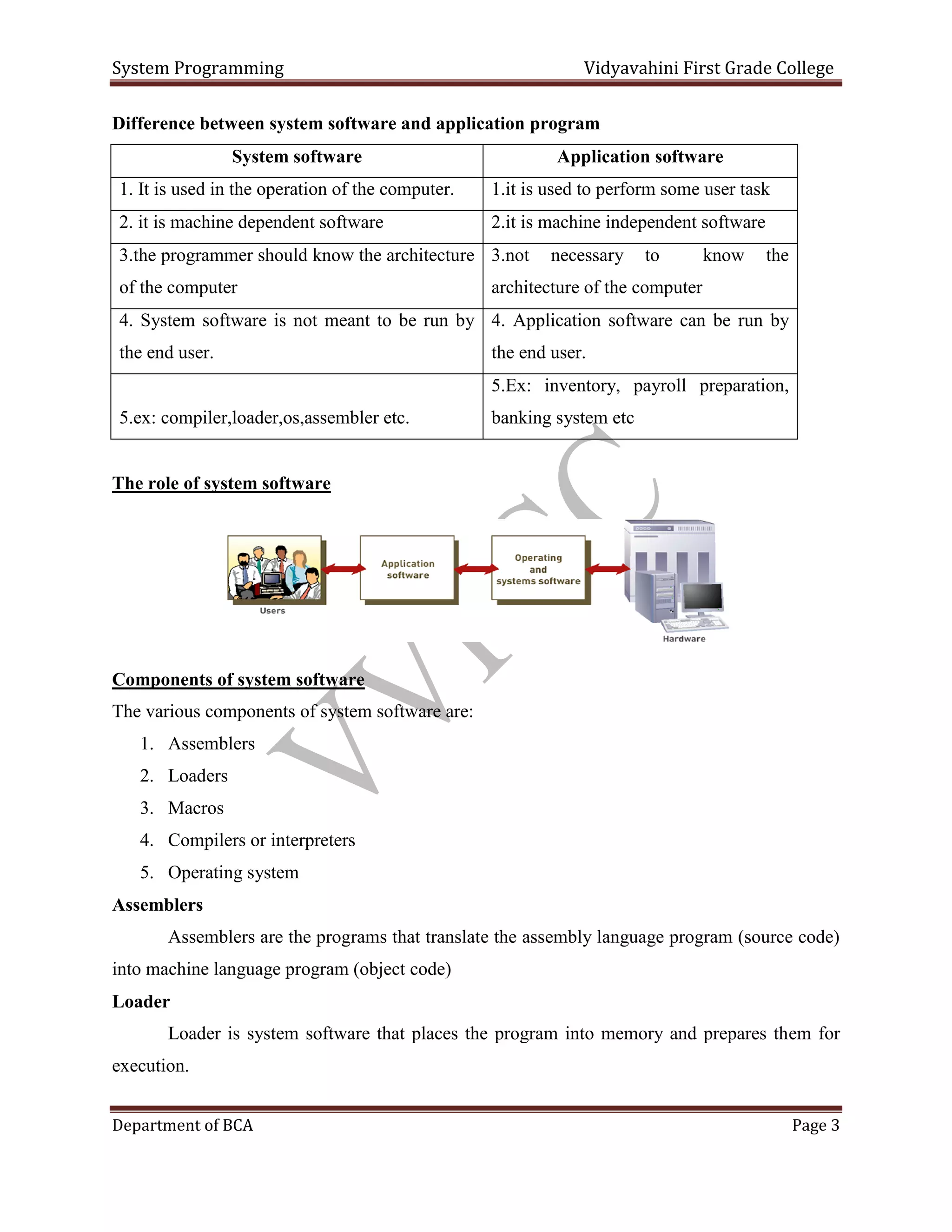
- An overview of system software vs application software, including examples of each. System software includes operating systems and aids the operation of the computer, while application software is for specific tasks.
- Descriptions of key components of system software like assemblers, loaders, macros, compilers and operating systems. Assemblers translate assembly code to machine code, loaders load programs into memory, and compilers translate high-level languages.
- Details about computer hardware components like memory, where data and instructions are stored, and processors that perform operations specified by instructions in memory.


![System Programming Vidyavahini First Grade College
Department of BCA Page 26
In SS format, the length is always on less than the data moved.i.e. If L=0 move 1 byte.
Here L=79, therefore move 80 bytes from location 1032[till 1111(1032+79)] to 1300[till
1379(1300 + 79)]](https://image.slidesharecdn.com/systemprogrammingvvnotes-220829144703-3dfad977/75/System-Programming-VV-Notes-pdf-26-2048.jpg)


![System Programming Vidyavahini First Grade College
Department of BCA Page 56
Chapter-4
Macro language and the macro processor
In most of the programs, we need to repeat same block of code several times, in such
situations macro facility is very useful
“Macro instructions are single line abbreviations for groups of instructions”
For every occurrence of macro instruction in a program the macro processing assembler
will substitute the entire block.
Advantages
The frequent use of macros can reduce programmer induced errors
They facilitate standardization.
Use of microprocessor
The most common use of macro processor is in assembly language programming
They can also be used with high level programming languages
They can also be used in operating system command language
General purpose microprocessors are not tied to any particular language
Macro definition
“In this phase we will attach a name to the sequence of instructions”
Structure
MACRO start of definition
[ ] macro name
------------
---------- Sequence of instructions
MEND end of macro definition.
The macro definition starts with “MACRO” pseudo opcode it indicates the beginning of
the macro definition
The following macro pseudo opcode we will give the name of the macro definition](https://image.slidesharecdn.com/systemprogrammingvvnotes-220829144703-3dfad977/75/System-Programming-VV-Notes-pdf-56-2048.jpg)


![System Programming Vidyavahini First Grade College
Department of BCA Page 80
1
2
3-5
6-72
73-80
Card type=1[indicates transfer card
Count type=0
Address of entry points
Empty
Cards sequence numbers
Algorithm for an absolute loader:
Statement 1: start
Statement 2: read header record [first record or first line]
Statement 3: program length
Statement 4: if[it is text card or transfer card ]
If it is text card, then store the data and instruction
Else
Transfer instructions
Statement 5: code is in character for then it will convert in to internal representation
Statement 6: read next object program
Statement 7: end
Advantages:
1. It is very simple and easy to implement.
2. More memory available to the user.
3. Multiple segments can be allowed at a time
Disadvantages:
1. In this loader program adjust all internal segment addresses. So that programmers must
and should know the memory management and address of the programs.
2. If any modification is done in one segment then starting address is also changed.
3. If there are multiple segments the programmer must and should remember the addresses
of all sub-routine.
Sub-routine linkages:](https://image.slidesharecdn.com/systemprogrammingvvnotes-220829144703-3dfad977/75/System-Programming-VV-Notes-pdf-80-2048.jpg)
![System Programming Vidyavahini First Grade College
Department of BCA Page 81
If one main program is transfer to sub program and that sub program also transfer to another
program.
The assembler does not know this mechanism [symbolic reference] hence it will declare the error
message. That situation assembler provides two pseudo-op codes. They are
1 EXTRN
2 ENTRY
The assembler will inform the loader that these symbols may be referred by other programs
1 EXTRN:
The EXTRN pseudo op code is used to maintain the reference between 2 or more subroutines.
OR
The assembler pseudo-op code EXTRN followed by a list of symbols indicates that these
symbols are defined in other programs but referenced in the present program.
2 ENTRY: The assembler pseudo-op code ENTRY followed by a list of symbols indicates that
these symbols are defined in present program and referenced i9n other program.
ENTRY pseudo-op code is optional which is used to defining entry locations of sub-routines.
Ex:
A START B START
EXTRN B USING *15
………… …………
L 15, =A (B) …………
BALR 14, 15 BR 14
……………
END END](https://image.slidesharecdn.com/systemprogrammingvvnotes-220829144703-3dfad977/75/System-Programming-VV-Notes-pdf-81-2048.jpg)
![System Programming Vidyavahini First Grade College
Department of BCA Page 82
Relocating loaders
In order to avoid the disadvantages of reassembling in absolute loader another type of loader
called relocating loader is introduced.
BSS [Binary Symbolic Subroutine] is one of the examples of relocating loader.
The BSS loader allows many procedure segments but only one data segment,
The assembler assembles each procedure segments independently and then passes to loader the
text and information as to relocation and inters segment reference
The output of a relocating assembler using a BSS scheme is the object program and information
about all other programs it reference
For each source program the assembler output a text prefixed by transfer vector that consist of
address containing names of the subroutines referenced by the source program.
The assembler would also provide to loader with additional information the length of the entire
program and length of the transfers’ vector.
This BSS scheme uses RX type instruction format
OP R1 X D
It is necessary to relocate the address portion of every instruction, the assembler associate a bit
with each instruction or address field called relocation bits. If relocation bit ==1 the
corresponding address filed must be relocated. If (rb==0) the field is not relocated.
The relocation bits are used to solve the problem of relocation, the transfer vector is used to solve
the problem of linking and the program length information is used to solve the problem of
allocation.](https://image.slidesharecdn.com/systemprogrammingvvnotes-220829144703-3dfad977/75/System-Programming-VV-Notes-pdf-82-2048.jpg)

![System Programming Vidyavahini First Grade College
Department of BCA Page 84
Length
There are again ESD cards classified into 3 types of mnemonics. They are:
1. SD [Segment Definition]: It refers to the segment definition [01]
2. LD; It refers to the local definition [ENTRY] [02]
3. ER: it refers to the external reference they are used in the [EXTRN] pseudo op code [03]
2 TXT Card: It contains the actual information are text which are already translated.
3 RLD Card: This card contains information about location in the program whose contexts
depends on the address at which the program is placed.
In this we are used ‘+’ and ‘–‘sign, when we are using the ‘+’ sign then no need of relocation,
when we are using ‘-‘sign relocation is necessary.
The format of RLD contains:
1. Reference number
2. Symbol
3. Flag
4. Length
5. Relative location
4 END Card: It indicates end of the object program.
Note: The size of the above 4 cards is 80 bytes
Design of direct linking loader:
Here we are taking PG1 and PG2 are two programs
The relative address and secure code of above two programs is written in the below
ESD Cards:
In a ESD card table contains information necessary to build the external symbol dictionary or
symbols table](https://image.slidesharecdn.com/systemprogrammingvvnotes-220829144703-3dfad977/75/System-Programming-VV-Notes-pdf-84-2048.jpg)

![System Programming Vidyavahini First Grade College
Department of BCA Page 86
RLD Card Format for PG1:
Source card reference
address
ESD ID Length
[bytes]
Flag
+ or -
relative
6
7
9
10
10
10
02
02
03
02
03
02
4
4
4
4
4
4
+
+
+
+
+
-
40
44
52
56
56
56
ESD Card for program2 [PG2]:
Source Card
reference
Name Type Id ADDR Length
12
13
14
14
PG2
PG2ENT1
PG1ENT1
PG1ENT2
SD
LD
ER
ER
01
-
03
03
0
16
-
-
36
-
-
-
Text Card for PG2:
Source card reference Relative address content
16
17
18
24-27
28-31
32-35
0
15
-3
16=A (PG1ENT1) =0
17=A (PG1ENT2+15) =0+15=15
18=A (PG1ENT2-PG1ENT1-3) =0-0-3=-3
RLD Card for PG2:
Source card ESD ID Length[flag] Flag Relative](https://image.slidesharecdn.com/systemprogrammingvvnotes-220829144703-3dfad977/75/System-Programming-VV-Notes-pdf-86-2048.jpg)
![System Programming Vidyavahini First Grade College
Department of BCA Page 87
reference [bytes] + or - address
16
17
18
18
01
-
03
03
4
4
4
4
+
+
+
-
24
28
32
32
Specification of data structure:
1 Pass1 database:
1. Input object decks
2. The initial program load addresses [IPLA]: The IPLA supplied by the programmer or
operating system that specifies the address to load the first segment.
3. Program load address counter [PLA]: It is used to keep track of each segments
assigned location
4. Global external symbol table [GEST]: It is used to store each external symbol and its
corresponding assigned core address
5. A copy of the input to be used later by pass2
6. A printed listing that specifies each external symbol and its assigned value
2 Pass2 database:
1. A copy of object program is input to pass2
2. The initial program load address [IPLA]
3. The program load address counter [PLA]
4. A table the global external symbol table [GEST]
5. The local external symbol array [LESA]: which is used to establish a correspondence
between the ESD ID numbers used on ESD and RLD cards and the corresponding
External symbols , Absolute address value
Format of data bases:
Object deck:
The object deck contains 4 types of cards](https://image.slidesharecdn.com/systemprogrammingvvnotes-220829144703-3dfad977/75/System-Programming-VV-Notes-pdf-87-2048.jpg)
![System Programming Vidyavahini First Grade College
Department of BCA Page 88
1 ESD Card format:
Source card
reference
Name Type ID Relative
address
length
Type Hexa-decimal
SD 01
LD 02
ER 03
2 TEXT Card:
Source card reference
address
Relative
address
content
3 RLD Card:
Source card
references
ESD ID Length Flag
+ or -
Relative address
Note: The length of each card is 80-bytes
4 Global External Symbol Table [GEST]:
It is used to store each external symbol and its corresponding core address.
External symbol
[8 bytes] character
Assigned core
[4 bytes] address decimal
“PG1bbbbb”
“PG1ENT1b”
104
124
5 Local external symbol array[LESA]:](https://image.slidesharecdn.com/systemprogrammingvvnotes-220829144703-3dfad977/75/System-Programming-VV-Notes-pdf-88-2048.jpg)
![System Programming Vidyavahini First Grade College
Department of BCA Page 89
The external symbol is used for relocation and linking purpose. This is used to identify the RLD
card by means of an ID number rather than the symbols name. The ID number must match an SD
or ER entry on the ESD card
Assigned core address of
corresponding symbol [4 bytes]
104
124
134
….
….
This technique saves space and also increases the processing speed.
Pass1 Algorithm and Flowchart:
The purpose of pass1 is to assign location to each segment and also finding the values of all
symbols
1. Initial program load address [PLA] its set to the initial program load address [IPLA]
2. Read the object card
3. Write copy of card for pass2
4. The card can be any one of the following type
i) Text card or RLD card- there is no processing required during pass1 and then
read the next card
ii) ESD card is processed based on the type of the external symbols
a) SD is read the length field LENGTH from the card is temporarily saved in
the variable SLENGTH. The value, VALUE toassign to this symbol is set
to the current value of the PLA.
The symbol and its assigned value are then stored in the GEST. If the
symbol already existed in the GEST then this is an error.](https://image.slidesharecdn.com/systemprogrammingvvnotes-220829144703-3dfad977/75/System-Programming-VV-Notes-pdf-89-2048.jpg)
![System Programming Vidyavahini First Grade College
Department of BCA Page 90
b) The symbol and its value are printed as part of the load map. LD is read
the value to be assigned is set to the current PLA+ the relative address
[ADDR]. The ADDR indicates on the ESD card
c) ER symbols do not required any processing durating pass1
iii) When an END card is encountered the program load address is incremented
by length of the segment and saved on SLENGTH.
iv) EOF card is read pass1 is completed and control transfer to pass2
Pass2 Algorithm and Flowchart:
1. If an address is specified in the END card then that address is used as the executed start
address otherwise, the execution will begin from the first segment
2. In pass2 the five cards are read one by one described as follows
At the beginning of pass2 the program load address is initialized as in pass1 and the
execution start address [EXADDR] is set to IPLA.
i. ESD card
a) SD type=>the length of the segment is temporarily saved in the variable
SLENGTH. The LESA [ID] is set to the current value of the PLA.
b) LD type=> Does not requires any processing during pass2
c) ER type=>the guest is searched for a match with the ER symbols. If it is not
found then there is an error. If found in the GEST its value is extracted and the
corresponding LESA entry is set
ii. Text card: The text card is copied from the card to the appropriate relocated
memory location [PLA+ADDR]
iii. RLD card: The value to be used for relocation and linking is executed from the
LESA [ID] as specified by the ID field.](https://image.slidesharecdn.com/systemprogrammingvvnotes-220829144703-3dfad977/75/System-Programming-VV-Notes-pdf-90-2048.jpg)
![System Programming Vidyavahini First Grade College
Department of BCA Page 91
Depending upon the flag values is either added to or subroutine from the address
constants
iv. END card: If an execution start address is specified on the END card it is saved
in a variable EXADDR. The PLA is incremented by length of the segment and
saved in SLENGTH, becoming the PLA for the next segment
[PLA=PLA+SLENGTH]
v. EOF card: The loader transfers control to the loaded program at the address
specified by the current contents of the execution address variable [EXADDR]
Other loading segments:
Binders:
In order to avoid the disadvantages of direct linking divides the loading process into 2 separate
programs:
1. A binder
2. A module loader
Binder is a program that performs the function as direct linking loader in binding together. It
outputs the text as a file or card deck, rather than placing the relocated and linked text directly
into memory.
The output files are in format ready to be loaded and are called a load module
The module loader loads the module into memory
The binder performs the function of the allocation, relocation and linking
The modules loader performs the function of loading.
There are 2 major classes of binders:
1. Core image builder
2. Linkage editor
1 Core image builder: A specific memory allocation of the program is performed at a time that
the subroutines are bound together. It is called a core image module and the corresponding
binder is called a core image builder](https://image.slidesharecdn.com/systemprogrammingvvnotes-220829144703-3dfad977/75/System-Programming-VV-Notes-pdf-91-2048.jpg)

![System Programming Vidyavahini First Grade College
Department of BCA Page 93
A 25k
B 15k
C 20k
D 30k
E 20k
Subroutine calls and procedures
Above figure illustrate a program consist of five sub programs [A to E] and that requires 110k
bytes of memory
The arrow indicator that sub program ’A’ only calls ‘B’, ‘D’ and ‘E’ sub program ‘B’ only calls
‘C’ and sub programs ‘C’, ‘E’ does not calls only other sub programs or routines
Note that procedure ‘B’ and ‘D’ are never use at the same time
Overlay Loading scheme:
Total required 65b memory is enough at a time. The portion of the loader the necessary
procedure is called as overlay supervisor or simply the flipper. This scheme is called as dynamic
loading or load on call.
Dynamic linking:
The main disadvantages of all of the previous loading scheme are that the sub routine as
references but they never executed, but the loader still in use the overhead of linking the
subroutines.
This mechanism the loading linking of external references are postponed until execution time the
loaded only the main program if the main program should execute a transfer instruction to an
external address or external variable the loader is call.](https://image.slidesharecdn.com/systemprogrammingvvnotes-220829144703-3dfad977/75/System-Programming-VV-Notes-pdf-93-2048.jpg)

![System Programming Vidyavahini First Grade College
Department of BCA Page 95
Chapter-6
Compiler
Compiler is system software components that accepts a program return in a high level language
and produce an object program
The compiler must perform the following 4 tasks [functions]:
1. Recognize certain strings as basic elements or token i. e., variables, operator’s
keywords etc.
2. Recognize combinations of elements as synthetic units and interpret their meaning.
3. Allocates strong and assign location for all variables in the program
4. Generate the appropriate object code
General model of a compiler:
Ex:
WCM: procedure (Rate, Start, finish);
Declare (Cost, Rate, Start, Finish) fixed binary (31) static;
Cost=Rate *(Start- Finish) +2*Rate*(Start-Finish-100);
Return (Cost);
End;
1 Recognize basic elements are tokens:
Step1:
“The source program was broken to pieces of blocks called as tokens”.](https://image.slidesharecdn.com/systemprogrammingvvnotes-220829144703-3dfad977/75/System-Programming-VV-Notes-pdf-95-2048.jpg)


![System Programming Vidyavahini First Grade College
Department of BCA Page 101
Identifiers table for above example:
Name Base Scale Prerecession Storage
class
relative
Cost
Rate
Start
finish
Binary
Binary
Binary
Binary
Fixed
Fixed
Fixed
Fixed
31
31
31
31
Static
Static
Static
static
0
4
8
12
Identifiers table consists of size fields:
1. Name: it specifies the name of the variable
2. Base: binary or decimal
3. Scale: Fixed or Float
4. Precisions: number of digits and used floating point number, a scale factor
Storage classes are:
1. Static
2. Automatic
3. Controlled
4. Base
The storage allocation routine scans the identifier table and assigns location to each scalar
Since the data type of each variable is of fixed (32) bits, the relative location 0 is assigned to the
first variable, 4 for second variable, 8 for third variable and 12 for fourth variable
Each variable of size 32 bite the first bit is reserved for representing sign bit. The sign bit is
allocated during load time
This relative addresses are used by the later phases of the compiler for proper accessing similarly
storage is also assigned for the temporary locations that will contain intermediate results of the
matrix
Sign Data [Binary or decimal]](https://image.slidesharecdn.com/systemprogrammingvvnotes-220829144703-3dfad977/75/System-Programming-VV-Notes-pdf-101-2048.jpg)
![System Programming Vidyavahini First Grade College
Department of BCA Page 102
Ex:[ M1, M2, M3,………M7]
4 Code generations: The code generation phase taking the input in matrix form and generating
the object code for each and every entry defined in the table
Each entry in the matrix and with the associated object code is defined by a table called as
production on table
Ex:
Start – Finish
The operator -> In matrix is treated as a macro call
The operands start and finish -> Is treated as macro arguments
Operator operand1 operand2
L 1,&operand1
S 1,&operand2
ST 1,&N
The following code can be generated the above statement using code definition of the
operator minus.
L 1,start
S 1,finish
ST 1,M1](https://image.slidesharecdn.com/systemprogrammingvvnotes-220829144703-3dfad977/75/System-Programming-VV-Notes-pdf-102-2048.jpg)
![System Programming Vidyavahini First Grade College
Department of BCA Page 103
Optimization [machining dependent]:-
Removing or deleting the duplicate entries in the matrix and modifying aii reference to the
deleted entries.
Matrix with common sub expressions Matrix after elimination of common sub
expressions
M1 – Start Finish
M2 * Rate M1
M3 * 2 Rate
M4 – Start Finish
M5 – M4 100
M6 * M3 M5
M7 + M2 M6
M8 = Cost M7
M1 – Start Finish
M2 * Rate M1
M3 * 2 Rate
M4
M5 – M1 100
M6 * M3 M5
M7 + M2 M6
M8 = cost M7](https://image.slidesharecdn.com/systemprogrammingvvnotes-220829144703-3dfad977/75/System-Programming-VV-Notes-pdf-103-2048.jpg)
![System Programming Vidyavahini First Grade College
Department of BCA Page 104
Optimization [machine dependent]:-
This phase has reduced both the memory space and the execution time of the object program.
Since these two factors is dependent on machine. The type of optimization is known as machine
dependent optimization.
Assembly phase:
The code generating phase is producing assembly language or the process of generating the
actual code is known as assembly phase
The assembly phase must perform these operations:
1. Resolve label references
2. Calculate addresses
3. Generate binary machine instructions](https://image.slidesharecdn.com/systemprogrammingvvnotes-220829144703-3dfad977/75/System-Programming-VV-Notes-pdf-104-2048.jpg)
![System Programming Vidyavahini First Grade College
Department of BCA Page 105
4. Generate storage
5. Convert literals
General model of complier:
There are 7 distinct logical problems
1. Lexical analysis
2. Syntax analysis
3. Integration phase
4. Machine independent optimization
5. Storage assignment
6. Code generation
7. Assembly and output
1 lexical analysis: Recognition of basics element or tokens and creation of uniform single table
2 Syntax analyses: Recognition of basics syntactic construct through reduction table
3 Interpretation phases: It describes the definition of exact meaning, creation of matrix and
tables for respective routine [action routings]
4 Machine independent optimization: Creation of most optimal matrix [removes the duplicate
entries in the matrix table]
5 storage assignment: It makes entries in the matrix that allow code generation to create code
that allocates dynamic storage and also the assembly phase to reserve the proper amount of
STARTIC storage
6 Code generation: A macro processor is used to produced more optimal assembly code
7 Assembly and Output: It resolving symbolic address and generating the machine language](https://image.slidesharecdn.com/systemprogrammingvvnotes-220829144703-3dfad977/75/System-Programming-VV-Notes-pdf-105-2048.jpg)

![System Programming Vidyavahini First Grade College
Department of BCA Page 107
3 Terminal table: This table is created by lexical analysis phase and contains all variable in the
program
4 Identifier table: It contains all variable in the program and temporary storage [Ex M1, M2,
M3 … M7] and information needed to reference allocate storage for the variables. This table is
created by lexical analysis
5 Literal tables: It contains all contents in the program
6 Reductions: It is a permanent table of decision rules in the form of pattern for matching with
the uniform symbols table to discover synthetic structure.
7 Matrix: Matrix is created by the intermediate form of the program which is created by the
action routine. It is optimized and then used for code generation
8 Code productions: It is permanent table of definition. There is one entry defining code for
each matrix operator.
9 assembly code: The assembly language variation of the program which is created by the code
generation phase and it is input to the assembly phase
10 Re-locatable object codes: The final output of the assembly phase ready to be use as input to
loader
Phases of compiler
1 Lexical phase:
The lexical phase performs the following three tasks:
1. Recognize basic elements are tokens present in the source code
2. Build literal and an identifier table
3. Build a uniform symbol table
Database:](https://image.slidesharecdn.com/systemprogrammingvvnotes-220829144703-3dfad977/75/System-Programming-VV-Notes-pdf-107-2048.jpg)
![System Programming Vidyavahini First Grade College
Department of BCA Page 108
Lexical phase involves the manipulation of 5 databases
1. Source program
2. Terminal table
3. Literal table
4. Identifier table
5. Uniform symbol table
1 Source program: The original form of the program created by the user
2 Terminal table: It is a permanent database it consist of 3 fields
Symbol: operators, keywords and separators [(,;,:]
Indicators: values are YES or NO
Yes=> operators, separators
No=> Keywords
Precedence: Used in later phase
Step Symbol Indicator Precedence
1
2
3
4
5
6
7
8
9
10
:
;
(
)
,
*
Declare
Procedure
+
-
Yes
Yes
Yes
Yes
Yes
Yes
No
No
Yes
Yes
Symbol Indicator precedence](https://image.slidesharecdn.com/systemprogrammingvvnotes-220829144703-3dfad977/75/System-Programming-VV-Notes-pdf-108-2048.jpg)


![System Programming Vidyavahini First Grade College
Department of BCA Page 111
Implementation:
1 The input strange is separated into tokens by break character. Brake characters are denoted by
the contents of a special field in the terminal table
2 lexical analysis 3 types of tokens:
1. Terminal symbols [TRM]
2. Identifiers [IDN]
3. Literals [LIT]
If symbol== TERMINAL table then
Create uniform symbol table of type TRM
3 Else if symbol==IDENTIFIER table then
Create uniform symbol table of type IDN
4 Else
Create uniform symbol table of type LIT
End if
2 Syntax Phase:
The functions of the syntax phase are
1. To recognize the major construct of the language
2. To call the appropriate action routines that will generate the intermediate form or matrix
form the constructs
Databases:
1 Uniform symbol table: The table create a by lexical phase
The uniform symbols are the source of input to the stack which s used by syntax and
interpretation phase
Table classes index
2 Stack: The stack is a collection of uniform symbol i.e., currently being worked on the stack is
organized in LIFO technique](https://image.slidesharecdn.com/systemprogrammingvvnotes-220829144703-3dfad977/75/System-Programming-VV-Notes-pdf-111-2048.jpg)


![System Programming Vidyavahini First Grade College
Department of BCA Page 116
Functions of Linking are Static linking and dynamic linking.
What is Dead code?
In computer programming, dead code is a section in the source code of a program which is
executed but whose result is never used in any other computation. The execution of dead code
wastes computation time and memory.
Explain CRT [Cross Reference Table].
The cross reference table is a data structure that replaces a run-time lookup computation with a
much simpler lookup operation.
The gain in processing speed can be significant because retrieving a value from memory is much
faster than performing a database or other connector lookup.
Cross reference table lookups are most often performed in map functions,
but can also be used as parameter values in all process steps that use parameters, such as
connectors (including the Start shape), Decision, Set Properties, Message, Program Command,
and Exception shapes.
Some common uses of a cross reference table are:
A simple value translation between System A and System B, such as item codes, units of
measure, status codes, or any other type of code
Reusable translations (for example, U.S. state abbreviations)
Switch/case logic (simple if/else)
Atom-specific map default values
Atom-specific connection default values (Start shape criteria)
To parameterize any process step with Atom-specific values for deployment to multiple
locations or customers
The cross reference table is easy to use and requires no coding. It is comprised of a set of data
elements (or values) that are organized using a model of rows and columns.](https://image.slidesharecdn.com/systemprogrammingvvnotes-220829144703-3dfad977/75/System-Programming-VV-Notes-pdf-116-2048.jpg)