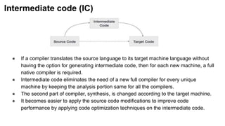
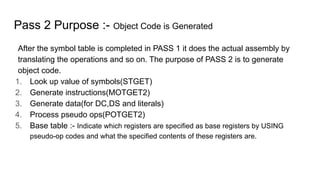
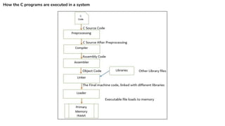
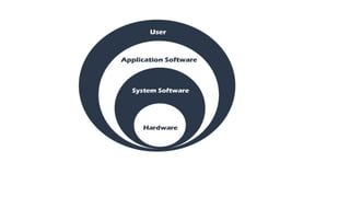
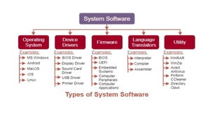
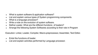
The document outlines the fundamentals of operating systems, data structures, and system software, explaining the distinctions between application and system software, their interactions, and essential functions. It delves into components like assemblers, loaders, and language processors, highlighting their roles in translating and executing programs, as well as detailing the workings of assembly language and the assembler's functionality. Additionally, it discusses the iterative process of software development and the significance of various programming paradigms in bridging the gaps between different domains of execution.


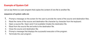


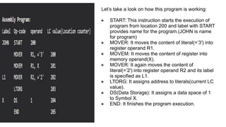
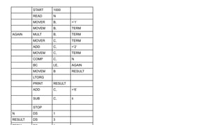
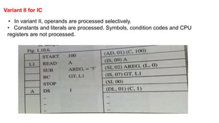
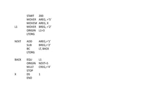
![Format of Assembly language Statement
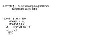
● Assembly language statements are entered one statement per line. Each
statement follows the following format −
[label] ,mnemonic/opcode ,operand specification, [;comment]
● The fields in the square brackets are optional.
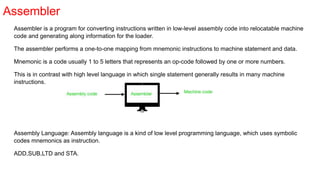
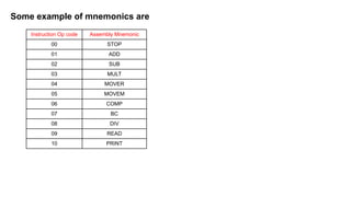
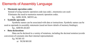
● A basic instruction has two parts, the first one is the name of the instruction (or the
mnemonic), which is to be executed. Eg. ADD , SUB, MOVE
● First operand is always register. Eg. R1, R2, R3
● Second operand is memory word using symbolic name.
● Eg. ADD R1 ONE/1](https://image.slidesharecdn.com/spcc-240220152159-265b7543/85/SPCC-System-programming-and-compiler-construction-42-320.jpg)