SlideShare a Scribd company logo
Superalloy Technology–A Perspective on Critical Innovations for
Turbine Engines
Robert Schafrik1,a
and Robert Sprague2,b
1
GE Aviation, Materials & Process Engineering Department, 1 Neumann Way, M/D H85,
Cincinnati, OH 45241, USA
a
robert.schafrik@ge.com
2
GE Aviation, Materials & Process Engineering Department, retired
b
robert.sprague@mac.com
Keywords: high temperature structural materials, nickel-based superalloys, aero-
propulsion, vacuum arc melting, investment casting, forging, materials modeling
Abstract: High temperature structural materials, such as nickel-based superalloys, have
contributed immensely to societal benefit. These materials provide the backbone for many
applications within key industries that include chemical and metallurgical processing, oil and gas
extraction and refining, energy generation, and aerospace propulsion. Within this broad application
space, the best known challenges tackled by these materials have arisen from the demand for large,
efficient land-based power turbines and light-weight, highly durable aeronautical jet engines. So
impressive has the success of these materials been that some have described the last half of the 20th
century as the Superalloy Age. Many challenges, technical and otherwise, were overcome to
achieve successful applications. This paper highlights some of the key developments in nickel
superalloy technology, principally from the perspective of aeronautical applications. In the past, it
was not unusual for development programs to stretch out 10 to 20 years as the materials technology
was developed, followed by the development of engineering practice, and lengthy production scale-
up. And many developments fell by the wayside. Today, there continue to be many demands for
improved high temperature materials. New classes of materials, such as intermetallics and ceramic
materials, are challenging superalloys for key applications, given the conventional wisdom that
superalloys are reaching their natural entitlement level. Therefore, multiple driving forces are
converging that motivate improvements in the superalloy development process. This paper
concludes with a description of a new development paradigm that emphasizes creativity,
development speed, and customer value that can provide superalloys that meet new needs.
Introduction
The modern world has made great use of high strength structural materials to design facilities and
equipment that we cannot live without. Structural materials are the backbone of any mechanical
system since they must support the loads and endure the degradation modes of the operating
environment. The critical roles played by materials that reliably serve under difficult conditions is
impressive. For example, electric generating plants, oil refineries, chemical processing plants,
industrial furnaces, and aircraft engines all depend on nickel-based superalloys. Our industrial age
could hardly exist without the capabilities enabled by these materials. But the public is generally not
aware of these materials since they are specialized and oftentimes are not directly observed.
The aviation industry, with its current fleet of airplanes powered by fast, fuel efficient, quiet
engines, would not be possible without superalloys. Jet engines are particularly challenging for
structural materials since the operating environment is hot, loads are high to minimize weight,
stiffness is crucial to maintain clearances throughout the operating envelope, critical structural
components are buried deep within the engine and not easily accessible for inspection and repair,
and the expectation is that the engine will operate for 30 years, or more, safely carrying passengers
and cargo. Imagine how different our society would be if people could not travel quickly and
inexpensively to any destination throughout the world. In a real sense, jet travel is one of the
Key Engineering Materials Vol. 380 (2008) pp 113-134
Online available since 2008/Mar/25 at www.scientific.net
© (2008) Trans Tech Publications, Switzerland
doi:10.4028/www.scientific.net/KEM.380.113
All rights reserved. No part of contents of this paper may be reproduced or transmitted in any form or by any means without the written permission of TTP,
www.ttp.net. (ID: 117.207.35.201-03/11/12,03:19:50)
hallmarks of our modern age since its
invention in the late 1920s. And the long-term
demand for travel by airplane continues to
grow, spurred on by its affordability for the
average family in countries throughout the
world. Another key reason for this growth is
that travel by air has become exceedingly safe:
the probability of life lost, or injury, during air
travel is considerably less than that of
highway travel, for example.
Early jet engine materials. The first jet engines necessarily relied on steels, especially the
stainless steels, for hot-section components, as these were the only strong heat resistant alloys
available. The temperature limitations and weight of these materials led many to forecast that jet
engines for powered flight would never be practical.
The search for alloys with greater high-temperature strength (such as creep) started in Europe
with the development of the Nimonic alloy series in Great Britain and the Tinidur alloys in
Germany. Within the United States, the Inconel series alloys were originally developed to provide
Overview of Jet Engine Fundamentals
In order to understand the application
of superalloys to jet engines, a fundamental
understanding of engine operation is
useful. Basically, jet propulsion is that
propelling force generated in the direction
opposite to the flow of a pressurized mass
of gas that exits through the jet nozzle.
Thus a modern jet engine combines the
principles of a simple water wheel with
that of garden hose nozzle, except that gas
rather than water generates the propulsive
force.
For the typical turbofan jet engine (Figure
1), air is continuously drawn into the
engine inlet and pressurized by a large fan.
This pressurized air exiting the fan either
flows directly back into the atmosphere
through a propulsive nozzle to provide
thrust, or flows into the jet engine “core”.
In the core, a compressor further boosts the
air pressure, a combustor mixes in fuel and
burns it at constant pressure, and the hot
gas is expanded through a high pressure
turbine which provides energy to drive the
compressor. The gas exiting the high
pressure turbine then further expands
through a second low pressure turbine
which, in turn, drives the front fan. The
core air exiting the low pressure turbine
flows through a propulsive nozzle
providing additional engine thrust.
The fraction of fan air which flows
around the engine core versus that portion
which flows into the core is called the
“bypass ratio”. The higher this ratio, the
more fuel efficient the engine. Thus, most
large commercial aircraft, have engines with
bypass ratios on the order of 4:1 to 8:1.
Figure 2 shows a cut-away view of a modern
high bypass ratio turbofan engine.
From a thermodynamic perspective, the
engine can be modeled as a Brayton heat
engine. High thermodynamic efficiency
requires high operating temperatures to
improve turbine efficiency and achieve
higher power levels. Thus there has been a
relentless quest for more capable materials in
advancing jet engine technology.
LowPressure
Turbine
Fan
Combustor
HighPressureTurbine
Compressor
LowPressure
Turbine
Fan
Combustor
HighPressureTurbine
Compressor
Fig 1: Three Dimensional Cross-Section of a
High Bypass Jet Engine
Fig. 2: Three Dimensional Cut-Away of a
High Bypass Jet Engine
114 Innovation in Materials Science
high creep strength materials for exhaust-driven superchargers for piston engines. These early alloy
families and their derivatives have formed the basis for the materials revolution that has sustained
the industry for more than 60 years. Achieving a suitable property balance has been difficult and
has required significant processing advancements, as well as the more widely appreciated alloy
development.
The term superalloy refers to a class of nickel and cobalt based alloys specifically designed for
use under conditions of high temperature. Superalloys alloys are “super” because they possess
outstanding strength (tensile, creep and fatigue strength) and excellent ductility and toughness at
elevated temperatures (above 0.50 solidus temperature, and up to ~0.75 of the solidus) that no other
metallic system has been able to match.
During the 1950s, materials available for gas turbine engines were much improved in
temperature capability through chemistry changes (alloy development) and melting improvements.
The initial alloys used were primarily existing, prosaic solid solution strengthened alloys; they were
in effect derivatives of oxidation resistant ground-based turbine rotor stainless steels adapted for
aggressive conditions, such as high temperature oxidation and corrosive environments.
The addition of small amounts of titanium and aluminum (two reactive elements) to nickel
alloys were a crucial development: an intermetallic phase (Ni3Al), known as gamma-prime (γ′) was
precipitated. Gamma-prime is a highly effective strengthener that is extremely stable at high
temperatures. At the time of its discovery, γ′ in its coherent lattice form could not be resolved by
the then current metallography equipment, but its existence was uncannily inferred by materials
scientists–this truly ranks as one of the great discoveries of the 20th
century. Indeed, the U.S.
National Academy of Engineering highlighted High Performance Materials is as one of the top
engineering accomplishments of the 20th
century. [2]
Differences Between Commercial and Military Jet Engines
Considering the application regime, military fighter engines continually push the performance
envelope in every respect, such as high power, quick take-offs, high maneuver loads, and large
excursions in engine speed imposed by combat conditions. In contrast, commercial gas turbines
operate at lower take-off power settings, and do not experience rapid acceleration maneuvers.
Commercial engines operate for long periods at modest thrust settings.
Consequently, military engines make severe demands on structural materials, and require
more inspections and maintenance than do commercial engines. Indeed, commercial engines stay
on-wing (i.e., not require maintenance that removes them from the aircraft) for much longer
periods of time than military engines. These maintenance intervals are determined by the number
of thermal excursion cycles (for components limited by low cycle fatigue) and/or operating time
(for components limited by creep). The considerably longer expected time on wing for
commercial engines versus the more severe mission profile and operating environment for
military systems can result in different material selection for similar components between these
engine classes.
The commonalties of minimum weight designs, minimization of fuel burned, and stringent
man-rated reliability requirements apply to both mission profiles; more often than not, these
overarching commonalties plus the cost/benefit of dual use materials, drive alloy commonality
between military and commercial systems.[1]
Military fighter engines achieve higher thrust-to-weight ratios than transport engines by using
an augmentor, also known as an after-burner. The augmentor is essentially part of the exhaust
nozzle—fuel is injected into the augmentor air stream, where it is ignited to produce additional
thrust. This boost can amount to as much as a 50% increase in thrust. The augmentor nozzle also
contains movable flaps and seals that create a variable nozzle area, which provides additional
control of thrust output.
Key Engineering Materials Vol. 380 115
Alloy 718
56%
Other Ni
18%
PM
5%
Titanium
9%
Aluminum
5%
Fe-base
6%
Co-base
1%
Alloy 718
56%
Other Ni
18%
PM
5%
Titanium
9%
Aluminum
5%
Fe-base
6%
Co-base
1%
Further Superalloy Development
By the late 1950's, turbine engine developers were becoming limited by the mechanical and
temperature constraints of the stainless steels. Superalloys were soon targeted for rotating structure
components, such as turbine disks and turbine blades, and static structure components, such as
pressure cases and frames. But superalloys were not quickly adopted because of fabrication
difficulties, such as cracking during forging and strain-age cracking during post-weld heat
treatment.
Driven by the national commitment to Aerospace in the United States, significant funding was
made available to universities, and government and industrial laboratories, for alloy and process
development. Superalloy producers forecast large market growth arising from a number of sources:
advanced military aircraft, a growing commercial aircraft market, and the national commitment to
space systems. Consequently alloys emerged from laboratories at an unprecedented pace. The
sequence of discoveries of the effects of key alloying element additions and the development of
useful heat treatments were intertwined and often occurred independently in different locations.
Progress in new alloys was rapid, but also chaotic and undisciplined, and oftentimes done under the
cloak of “company proprietary” research and development.
Significant alloying and process improvements were made on the γ′-strengthened nickel-based
systems; new alloys were stronger at all temperatures of interest than predecessor alloys and were
capable of pushing the temperature envelope for applications. In a parallel, progress was made on
the gamma-double-prime (γ′′, Ni3Nb) strengthened iron-nickel base alloys. These alloys were
exemplified by alloy IN718. While not having quite the temperature capability of their γ′ cousins,
the γ′′ alloys possess high tensile strength and are more easily processed and welded. The sensitivity
of early γ′′ alloys to notch failure in creep rupture tests was readily corrected via improvements in
melt processing and sulfur control. IN718 quickly found adherents within the propulsion industry
due to its excellent balance of properties, reasonable cost, and its castability, forgeability, and
weldability. Indeed, more than 50 years after the introduction of IN718, the great majority of jet
engines use alloy 718 as the material of choice in applications below approximately 650°C
(1200°F). (Note: Alloy 718 has evolved from the first IN718, with chemistry and heat treatment
changes to optimize various properties.) Today, there are many variations of alloy 718 in use.
Therefore, the development of IN718 was seminal event in enabling modem turbine engines.[3]
IN718 is arguably the most successful superalloy to date.
Fig. 3 shows the breakout of metals used in GE Aviation
engine forgings in 2000. Note that alloy 718 accounted for
well over 50 percent of the total.[4]
Many factors contributed to the evolution of today's alloys.
Some of the significant discoveries that have guided
superalloy evolution include:
• Excessive alloying additions were found to result in
precipitate phase instability manifested by the gradual
formation of topological close packed (TCP) intermetallic
compounds. The result is that the alloy becomes embrittled
during service exposure by the acicular shape of the TCP
phases, usually in the grain boundaries, that effective act as
notches, and by the depletion of key elements from the matrix.
Obviously, the breath of alloy development is significantly
constrained by this phenomenon.
• It was discovered that slow precipitation, during service life, of phases considered non-
embrittling, such as carbides, actually degraded alloy strength. Therefore, carbide stability
within the application temperature window is a key consideration.
Fig. 3. Metals Used in GE Aviation
Engines during 2000
116 Innovation in Materials Science
• To allow heat treatment of most wrought alloys and many cast alloys for mechanical property
control, a meaningful difference (at least 30ºC, or 50ºF) between the hardening precipitate
phase solvus (dissolution) temperature and the alloy melting point is necessary. This permits
re-solutioning and re-precipitation of strengthening phases. This criterion effectively limits
the quantity of strengthening elements that can be added to the matrix since highly alloyed
metals tend to have little temperature separation between the liquidus and solidus
temperatures.
• Alloys can be tailored to optimize performance for specific environments, such as improved
oxidation or sulfidation resistance. However, this tailoring causes a reduction in other
mechanical and/or physical properties.
• Alloy compositions possessing the most desirable properties for each application were not
always producible in the design-required configuration due to inherent processing and
formability limitations.
• As more strengthening elements were added, the ductility of the resultant alloys was
concomitantly reduced. A major barrier was found at the minimum ductility point for turbine
airfoil alloys, usually between 650ºC and 760ºC (1200ºF and 1400ºF). This problem was
manifested by the creep rupture failure of turbine blade attachments. This problem also led to
strain-induced cracking of turbine airfoils during casting solidification and/or heat treatment.
This problem was addressed 3 ways:
(a) Engineers adopted a design rule that required airfoil alloys to have at least 2 percent
ductility at 760ºC. This limited the use of certain high creep strength alloys, but was
necessary to protect from the possibility of structural failure.
(b) It was discovered that the addition of a small amount of hafnium led to an acceptable
minimum ductility level for most alloys.
(c) Eventually the grain boundary ductility shortfall in high strength blade alloys was solved
by an unexpected processing breakthrough: directional casting solidification that
virtually eliminated grain boundaries in the principal stress direction.
• Strengthening of cobalt alloys is only possible by solid solution alloying and carbide
distribution. Cobalt alloys therefore lag nickel alloys in breath of application. But cobalt
alloys have several advantages over high temperature nickel alloys: higher melting point, and
therefore higher use temperature capability; better environmental resistance in certain
environments; and better weldability since they are solid solution strengthened. These factors
combined to make cobalt advantageous in static part applications that do not require high
strength.
Environmental Resistant Coatings
The progress made in alloy development (and casting technology) provided significant
improvement in turbine blade performance. Continued increases in turbine temperature resulted in
mechanical and physical property imbalance when it became apparent that the environmental
resistance of highly capable turbine airfoils alloys did not possess necessary durability. This was
attributable to several factors. First, the intrinsic environmental resistance of the alloys naturally
decays with escalation in operating temperature; second, the alloying elements that impart creep
resistance often compromise environmental properties; and third, elements that provide
environmental resistance perversely encourage the formation of brittle TCPs.
Hence as alloy compositions continued to achieve greater high temperature strength,
environmental degradation of uncoated airfoil surfaces, including internal cooling passages, became
a leading concern regarding deterioration and maintenance cost. Thus improvements in coating
technology were required to allow the alloy benefits to be fully exploited.
In response to this need, oxidation resistant coatings were developed and applied to airfoils to
improve environmental resistance. Initial coatings were “pack” coatings, which diffuse aluminum
into an airfoil surface, forming an adherent and oxidation resistant layer of NiAl, typically 0.08µm
Key Engineering Materials Vol. 380 117
to 0.13µm (3 to 5 mils) in thickness. However this improvement in oxidation resistance caused a
loss of surface ductility due to the inherent coating brittleness. Design engineers learned to adjust
their design practices to accommodate this fatigue penalty.
Production methods were developed to apply an aluminide coating by gaseous phase transport
to coat internal surfaces. Importantly, process engineers devised methods of masking the highly
loaded areas that should not be coated, such as dovetail attachments, thereby preventing premature
fatigue failure in highly stressed regions.
As metal surface temperatures continued to unrelentingly increase, further mitigation strategies
were necessary. Pure aluminide coatings were unable to sustain oxidation resistance at these higher
temperatures. In response, a superior, but more costly, family of coatings was founded and
implemented. These "overlay" coatings were highly oxidation resistant alloys containing chromium,
aluminum and yttrium plus solid solution strengtheners, such as cobalt and/or nickel. In line with
their elemental composition, they were designated MCrAlY (cobalt and nickel comprise the “M”).
They were applied by several different methods, such as plasma spray, electron beam vapor
deposition and sputtering. Often, these coatings were used in conjunction with diffusion coatings to
achieve enhanced resistance to deterioration by spalling.
The growth of coating technology occurred somewhat autonomously from high temperature
alloy design. What began serendipitously, in hindsight, soon became critical, as coating technology
became essential to the maturation of high temperature airfoil designs. Coated blades, with the aid
of film cooling, were now capable of operating at local temperatures close to the incipient melting
point of the alloy, and at bulk temperatures nearing the hardening phase (gamma prime) dissolution
temperature. Further hot section airfoil temperature advancements demanded a new concept to gain
further capability without employing even more cooling air.
The maximum gas temperature within a jet engine generally occurs during a transient condition,
e.g. commercial aircraft only attain maximum temperatures at take-off. Consequently, a means for
protecting the metal during these transients would allow reduction in cooling air requirements.
Fortuitously, certain ceramics have thermal insulating capabilities that are suitable for this transitory
condition. However, the concept of applying a ceramic thermal barrier coating (TBC) was not
without challenges. One concern was that a ceramic material would not adhere to the metallic
substrate, particularly after repeated thermal cycling, since the coefficients of thermal expansion of
the coating and the substrate are very different; this thermal strain would have to be accommodated.
Another concern was that the brittle ceramic layer would reduce fatigue life of the airfoil. Prior
experience of using TBCs on static components, notably combustion liners, and the knowledge that
analytical methods could be developed to deal with nil ductility coatings, suggested that success
was possible.
TBC’s, based on yttria-stabilized zirconia were successfully developed and applied to airfoils in
thin layers, typically 0.13µm to 0.25µm (5 to 10 mils) thickness. Conventional coating processes,
such as plasma spray and physical vapor deposition (PVD) were suitable for depositing high
quality, thin ceramic layers. The deposition process was further refined to avoid depositing TBC’s
in local areas through direct masking, or virtual masking; i.e., manipulation of the component
holding device during the coating sequence and to allow depositing variable thicknesses at selected
locations.
Fortuitously, the metallic oxidation-resistant coatings that were applied directly to the surface of
the superalloy to improve environmental resistance, also served as an intermediary layer for
bonding the ceramic to superalloys.
Current Superalloy R&D Directions
New Age Hardenable High Temperature Nickel Alloy. IN718 (now conventionally referred
to as alloy 718) has been immensely successful since it has an excellent balance of mechanical
strength, phase stability, and processability. A number of improvements have been made over the
years to alloy 718 in melting, ingot conversion, forging, and heat treatment.
118 Innovation in Materials Science
The gamma-prime-strengthened alloys typically are stronger but much less processable.
However, engine designers have been relentlessly increasing engine temperatures. The metastability
of the gamma-double-prime phase in alloy 718 above 650°C (1200°F) has been the key limitation
on its application. This has dictated the selection of gamma-prime alloys for applications that are
hotter than 650°C. However, these class of alloys, such as René 41 and Waspaloy, pose significant
component manufacturing challenges since they are not very weldable or easily formable, and are
prone to strain-induced cracking. Therefore, a long-standing need has been an alloy with the slow
precipitation kinetics of Alloy 718 that retains properties with up to 50°C (nominally 100°F )
greater temperature capability.[5]
Since the introduction of alloy 718, numerous alloy chemistries have attempted to match the
favorable processability of alloy 718 with increased thermal stability to higher temperatures. A
recent alloy, known as 718Plus®
, has shown phase stability sufficient for operating temperatures of
704°C for many applications. (718Plus®
is a trademark of ATI Allvac.) 718Plus material is a
derivative of alloy 718, with the major change being the addition of 9 weight percent cobalt,
reduction of 8 percent iron, Al/Ti of 2, Al+Ti of 2.15, and addition of 0.002 percent
phosphorus.[6,7] Table 1 compares the chemistry of the 718Plus material to alloy 718 and to
Waspaloy.
Table 1. Nominal Chemistries of Selected Superalloys (weight percent)
Alloy Ni Cr Mo W Co Fe Nb Ti Al
718 Bal. 18.1 2.9 - - 18 5.4 1 0.45
718Plus Bal. 18 2.8 1 9 10 5.4 0.7 1.45
Waspaloy Bal. 19.4 4.25 - 13.25 - - 3 1.3
The Allvac development program included both computer modeling and experimental melting
trials. The modeling work was useful in analyzing the optimum Al/Ti and Al + Ti levels. Key to
success of the alloy is its sluggish precipitation of gamma-prime, which is thought to be due to the
high niobium content in the gamma-prime phase.
An important aspect of this program is that it was selected for scale-up demonstration in non-
rotating components under a US Air Force program, Metals Affordability Initiative, which included
engine manufacturers (General Electric, Honeywell, and Pratt & Whitney), forgers (Firth-Rixon and
Ladish Co), primary metal producers (Allvac and Carpenter Technology), and the Air Force
Research Laboratory. This consortium approach helped insure that the material met market needs,
that there was a supply chain capable of producing the material and desired component forms, and
provided an effective mechanism to study and report on the understanding of the metallurgy of the
new alloy. A collaborative approach is becoming the desired way to conduct such programs to
reduce development time and application uncertainty.[8]
Improved Disk Alloys. Disks made via the powder metallurgy route have superior properties
owing to the better control of elemental segregation and finer grain size than can be achieved via
the conventional cast and wrought process. Powder metallurgy disks are not without challenges,
however, which include cleanliness and powder handling, consolidation into a defect-free structure,
heat treatment that produces desired properties, and added cost of the additional processing steps.
Nonetheless, most advanced disks are made via the powder metallurgy route since the overall
benefits outweigh the drawbacks.
Work during the 1990’s for NASA’s High Speed Civil Transport Program, which was aimed at
technology for a commercially viable supersonic flight vehicle, identified the need for a disk
material that could withstand long dwell fatigue cycles and creep/rupture loading cycles at
temperatures above 704°C (1300°F). A new disk material was developed in a consortium
comprised of General Electric, Pratt & Whitney, and NASA Glenn Research Center. The alloy was
designed to have an improved creep and fatigue resistant microstructure, combined with stronger
grain boundaries to handle high disk rim temperatures. To achieve the desired combination of
Key Engineering Materials Vol. 380 119
properties, the resultant superalloy, known as ME3, possesses the requisite temperature properties at
704°C; this was achieved through careful control of the grain boundary chemistry and precipitates,
and an optimum super solvus heat treatment that led to maximum performance within the operating
conditions of interest. [9,10]
Rolls Royce also developed a new powder disk alloy, RR1000, for a subsonic engine
application. They applied past experience, as well as advanced thermodynamic modeling capability
to predict phase stability and TCP formation. In order to encourage damage tolerance, this disk was
designed to have a minimum volume fraction of γ′ phase consistent with attaining the desired
strength level. The levels of Al, Cr, and Mo are within the range that was predicted to avoid TCP
formation. Near-solvus heat treatment and fan air-cooling of the forged material provide an
acceptable balance between tensile strength and damage tolerance.[11]
Next Generation Airfoil Materials. The development of a new airfoil alloy for the supersonic
application was also undertake by the General Electric, Pratt & Whitney, and NASA Glenn
Research Center consortium for the High Speed Civil Transport Program. Subsonic engines
accumulate hundreds of hot time hours, while supersonic engines accumulate thousands of such
hours. Therefore key goals of the program included microstructural stability to avoid degradation of
long-time properties, acceptable environmental resistance, and good castability and producibility.
Obtaining that balance of properties was challenging. In addition, the alloy had to avoid secondary
reaction zone (SRZ) instability that can develop beneath PtAl and MCrAlY coatings, and avoid the
formation of topologically closed packed phases. Reactive elements, Hf, Y, Ca, were key to
improving oxidation resistance. High creep-rupture required an increase in refractory element
content (Mo, W, Ta, Re). But achieving all of the requirements would not have been possible
without the addition of a platinum-group metal, ruthenium (Ru), which was discovered to be critical
to promoting microstructure stability. [12]
The High Temperature Materials 21 program, conducted at Japan’s National Institute for
Materials Science (NIMS) has been developing new single crystal alloys with superior creep
strength and microstructural stability, capable of operation in both subsonic and supersonic engine
applications. The primary emphasis has been to increase creep rupture strength at the higher
temperatures through a combination of data-driven modeling and key experiments to guide the
selection suitable chemistries. Using this approach, a number of high temperature airfoil materials
have been discovered. [13]
Process Technology
In parallel with the alloy improvements, and oftentimes leading it, developers made significant
improvements in the processes by which superalloy wrought and cast shapes could be produced.
The importance of these processing advances to the design of turbine engine components cannot be
over-emphasized. For example, weldability improvements in the nickel alloys allowed significant
increase in the size and complexity of cast structures by enabling weld repair of casting defects; this
allowed manufacture of complex-shaped components, such as frames, using only a few parts,
enabling lower component weight and higher reliability.
The synergistic interaction of materials and processes is depicted in Fig. 4. This figure
graphically demonstrates that each spiral of improvement contains both processing innovations and
material improvements for the entire suite of materials used in jet engines.
Materials processing requires invention, arduous process development, and large capital
investment. Thus it is often on the critical path for materials development and scale-up.
120 Innovation in Materials Science
Vacuum melting technology.
Advances in propulsion materials technology can arguably trace its roots to the point when vacuum
induction melting (VIM) became commercially feasible, about 1950. Prior to this, materials
researchers had recognized that vacuum melting increased elemental (and alloy) purity and that
certain properties were improved by purity enhancement. During the 1950s, commercial vacuum
pumps became available that sustained a vacuum level of 10µm gas pressure, and vacuum sealing
technology advanced so that leakage rates into the vacuum furnace could be minimized and
managed.
VIM process evolution permitted the elimination of detrimental trace and minor elements in
concert with the addition of reactive elements such as aluminum and titanium, without the risk of
these becoming oxide inclusions. This was truly a fundamental breakthrough for producing high
strength superalloys, since reduction in trace elements increased component reliability, and the
addition of reactive elements enabled precipitation strengthening of these alloys.
One of the first "clean metals" produced by VIM was AISI 52100 grade steel, a vintage bearing
steel that was adopted in early jet engine main shaft bearings. Bearing steels for flight-rated jet
engines had been made in an air-melt electric furnace, and consequently steel properties varied
widely due to the presence of multiple oxide inclusions. Bearing failures were common and had
serious consequences, such as an in-flight shutdown of the engine.
Bearing steels prepared by VIM were much cleaner than electric furnace steel, and VIM
processed steels rapidly became the preferred bearing steel. But these bearings surprisingly suffered
from rarely occurring, early failures in a few bearings. The source of the failures was found to be
randomly distributed exogenous ceramic inclusions that originated from erosion of the VIM furnace
liner, weir, and gating. Thus, VIM successfully removed indigenous inclusions, but the bearings
suffered the problem of rarely-occurring exogenous inclusions that caused infant mortality in a
small percentage of bearings.
Vacuum Arc Melting (VAR). Arc melting in air was first disclosed as a process for the
melting of metals in 1839. However, it was not widely practiced for the commercial production of
structural materials until after WWII, when vacuum technology became commercially available.
Consumable arc melting became a process that followed VIM for superalloys, because alloy
formulation and unique chemistry control is best achieved by VIM. VAR ingots in general have
Fig. 4. Synergistic Interaction of Materials and Processes
Titanium
Stainless Steel
Cobalt
Nickel Superalloys
Polymer Matrix
Composites
Thermal Barrier
Coatings
Vacuum Induction
Melting
Arc Melting
Investment Casting
of Complex Shapes
Powder Metal
Superalloys
Turbine Coatings
TIME
Directionally Solidified
and Single Crystal Airfoils
Multiple Vacuum
Melting Cycles
Intermetallics
Ceramic Matrix
Composites
1950s
1960s
1970s
1980s
1990s
2000s EB-PVD
Large Structural
Castings
Iso-Thermal Forging
SiC Melt Infiltration
Laser
MATERIALS PROCESSES
Titanium
Stainless Steel
Cobalt
Nickel Superalloys
Polymer Matrix
Composites
Thermal Barrier
Coatings
Vacuum Induction
Melting
Arc Melting
Investment Casting
of Complex Shapes
Powder Metal
Superalloys
Turbine Coatings
TIME
Directionally Solidified
and Single Crystal Airfoils
Multiple Vacuum
Melting Cycles
Intermetallics
Ceramic Matrix
Composites
1950s
1960s
1970s
1980s
1990s
2000s
1950s
1960s
1970s
1980s
1990s
2000s EB-PVD
Large Structural
Castings
Iso-Thermal Forging
SiC Melt Infiltration
Laser
MATERIALS PROCESSES
Key Engineering Materials Vol. 380 121
better homogenization and higher bulk density than VIM ingots due to greater control of the
solidification rate.
In the case of AISI 52100 bearing steel, a VAR cycle following alloy synthesis by VIM
dispersed the exogenous inclusions, and consequently eliminated infant mortality failures. Thus,
premium quality bearings are double vacuum melted (VIM-VAR) to the present time.
Premium Quality Melting. Superalloy premium quality practices have continued to evolve.
Premium quality (PQ) melting requires at least double vacuum melting, and some critical
applications require triple melting. The triple melt sequence results in very clean premium quality
material with minimal lot-to-lot variation, and therefore material with highly reproducible
mechanical properties and processability response.
In modern melt practice, VIM is the production option for the initial heat formulation to
establish alloy chemistry. Additional secondary refining is required, however, to satisfy stringent
cleanliness and homogeneity requirements. Defects introduced in VIM include non-metallic
inclusions, alloy segregation, and shrinkage cavity formation.
Electro-slag re-melting (ESR), a consumable electrode process, uses a controlled composition
slag to remove non-metallic inclusions while maintaining control of alloy chemistry. It is often used
as the second melting step for PQ material. ESR produces sound, improved cleanliness ingots, but
they can be prone to solidification segregation.
Therefore, a third melting step is employed for the most critical applications. Since VAR is
effective in establishing a reproducible macrostructure, and does not introduce defects if close
attention is paid to process details, it is usually reserved for the final melt step.
Investment Casting. Early turbine airfoils were produced from wrought alloys; the first
application of a casting for a rotating superalloy component occurred in the 1950s when a solid (i.e.,
non-cooled) turbine airfoil was investment cast. This event required improved processes to reduce
casting defects that limited strength. The driving forces for casting airfoils included increased
complexity in the design of airfoils to accommodate internal cooling air passages, and the eventual
discovery that airfoils could be cast as single crystals, greatly enhancing their creep rupture lives.
Improvements were also occurring for large structural castings, such as engine casings. The
primary driving forces were reduced cost and improved reliability through production of a
monolithic structure. While large structural castings are not subject to as demanding an environment
as airfoils, their large size and complex casting tooling adds unique challenges.
As design technology advanced, the relentless push for ever greater turbine inlet temperature
challenged the materials community. A key limitation was the creep strength capability of turbine
blades and vanes at higher operating temperatures. Engineering analysis indicated that significant
improvement in engine performance would be gained if the turbine blades were cooled by internal
conduction and by establishing a thin film of cooler air over the hottest regions of the blade. Since
the air would have to be pressurized to pass through the channels and holes, it was necessary to re-
direct, or “bleed”, a portion of the pressurized air in the compressor to the turbine blades for
cooling. Initially, this technology was implemented by drilling internal cooling air passages in
turbine blades, at high cost and extended shop cycle time.
Advances in investment casting technology (based upon the ancient “lost wax” process) soon
made wrought turbine blades obsolete. Central to this technology was the development of ceramic
core materials that could be placed inside the turbine blade casting mold to produce intricate
internal cavities; these ceramics had to be strong enough at molten superalloy temperatures to retain
shape, yet able to be completely removed after casting without damaging the casting itself. These
cores were found to be removable by caustic solutions contained in heated and pressurized
autoclaves, and this break-through paced the evolution of "cast-in" cooling passages.
The desire for strong turbine airfoil castings that required little or no subsequent machining,
even with elaborate internal cooling passages, was not realized without overcoming challenges
122 Innovation in Materials Science
which included alloy stability, ductility compromise and balance of properties between mechanical
strength and environmental resistance.
Directional Solidification. For most turbine airfoils, the principal stress direction lies in a
direction parallel to the airfoil length. Therefore, it was postulated that if the grain boundaries could
be aligned with this direction, airfoil life would be greatly enhanced. Spurred by this idea, Ver
Snyder and others, began developing the directional solidification (DS) casting process in which the
resulting grain boundaries were parallel to the airfoil length. The DS process was implemented as a
production process after substantial development effort.
DS airfoils provided an immediate 25ºC increase in creep strength; in addition the intermediate
temperature ductility was much improved, and thermal fatigue life greatly enhanced. DS also
resulted in greater tolerance to local strains and rupture ductility making it practical to inspect
airfoils that had been in-service for local evidence of damage accumulation, such as deformation
and/or incipient cracking prior to airfoil failure.
The DS process requires longer processing time and greater process control than does
conventional (i.e., "equiaxed grain") casting, and is therefore more costly. The irresistible benefits
of the technology culminated in widespread acceptance of DS despite its higher cost. DS
technology was soon followed by single crystal (SC) airfoil castings, which eliminated high angle
grain boundaries altogether, with further improvement in stress rupture life and an increase in
allowable blade operating temperature.
The oft-used gas turbine milieu term "forgiveness" implies a characteristic that imparts
detectable damage significantly prior to component fracture. DS and SC added a degree of
forgiveness to high temperature airfoils, and continue to be a prevention mechanism for catastrophic
airfoil failure. In today's modern turbine engine, nearly all the high- pressure turbine airfoils are
either directionally solidified or mono-crystals. So compelling is the cost/benefit ratio that the
technology is now used in the cost sensitive stationary gas power generators; single crystal castings
weighing up to 20kg are commonly produced for these applications.
Improving Wrought Superalloy Capability. In the domain of forging technology, several
significant innovations have been important. The first was the evolutionary change from open die
hammer to closed die press forging. Presses became larger in platen size and capacity, and
improved in temperature capability and die closure rate regulation. This new competence translated
into the production of large and complicated shape superalloy components, such as highly alloyed
turbine disks with diameters exceeding 1m. The benefits of press forging include part-to-part
uniformity of properties, allowing for standard heat treatment procedures that minimize component
cracking, and reduced residual stress gradient within components that adds to in-service reliability.
A second major innovation was isothermal forging of superalloy powder metallurgy billets.
Turbine disk rim temperatures increased as engine design engineers took advantage of
improvements in airfoil temperature capability. Alloy developers responded by increasing the
strengthening content of conventional disk alloys. However, these materials exhibited increased
resistance to deformation and decreased hot ductility; these effects combined to significantly
degrade malleability. These alloys could not be forged into even geometrically simplified shapes
without strain-induced cracking. Consequently, these new disk alloys that possessed both high creep
and tensile strength were disallowed for use.
An original motivation for powder metallurgy was that the rapid cooling rate during powder
formation minimized solidification segregation, allowing the complexity of superalloy chemistry to
be increased with commensurate improved temperature performance. Moore and Athey found that
deformation behavior of very fine grain size superalloys was sometimes superplastic; i.e., large
deformations could be achieved with relatively low press forces under the right combination of
strain, strain rate, and temperature. This behavior was used to produce disk alloys via the powder
metallurgy that could not be produced using conventional ingot metallurgy. Thus the powder
Key Engineering Materials Vol. 380 123
metallurgy route provided composition and processing flexibility for advanced alloys, albeit at the
expense of greater processing complexity and cost.
The manufacture of superalloy powders and the consolidation of the powder into fine grained
forging billets required additional innovations. These were contributed by a number of companies
and research institutions, and included:
• processing techniques to produce clean superalloy powder
• development of a molybdenum-based die material (Moly TZM) strong enough to deform
powder billet into complex shapes at 925ºC to 1100ºC (1700ºF to 2000ºF) at slow
isothermal forging rates
• enclosing the forging press within a vacuum chamber to environmentally shield the
molybdenum alloy dies and the piece being shaped
• establishment of controlled slow strain rate (superplastic) forging regimes
Near Net Shape Manufacturing. The high cost and long production lead times required to
make aerospace quality parts has spurred the search for improved processing methods that are
inherently more efficient and faster than the traditional casting, forging, and machining
manufacturing steps. A number of such processes are beginning to be used.[14] The inflationary
cost of nickel has been an important factor in the search for processes that require much less input
material to make a finished part. Many of the superalloy parts in an engine require 8 to 10 pounds of
input material for every 1 pound in the finished part. This excess material not only costs a
considerable amount, but the cost to remove it is also high.
Additive manufacturing, which can trace its roots to rapid prototyping, has been gaining ground
as an alternate processing method. The technology can quickly and economically directly make
prototypes of parts without requiring hard tooling or extensive post-processing. Additive
manufacturing is a process that produces part features, and entire parts, in a controlled layer-by-
layer fashion using various energy sources to melt powder metals. Geometric information contained
within a CAD data file guides the energy source in precise patterns over a layer of deposited
powder. When the energy beam hits the powder, it fuses them into the solid shape. “Additive
freeform manufacturing” and “layered manufacturing” are typical of this family of processes. This
technology currently accounts for a relatively small proportion of superalloy component
manufacturing, but many potential applications are under evaluation.
Additive manufacturing has challenges that must be met before these methods become accepted
as a fully capable, prime manufacturing methods. The technical challenges include greatly
increasing speed and material throughput—for instance, it can take a day or more to build-up an
average size part. Improvements are also needed in build-envelope size, accuracy, finish, resolution,
and detail. More choices of powder materials must available possessing the requisite cleanliness. A
likely path for introduction is combining additive manufacturing with other manufacturing
processes. For example, using additive manufacturing to produce lands and bosses on a streamlined
engine case can result in significant material savings.
Sprayforming is a near net shape process that allows direct build-up of semi-finished products in
one step. [15] In this technique, atomized droplets are sprayed onto a collector, where they fall into
a semi-liquid layer, solidify and build-up a preform. It can produce a uniform distribution of fine
grains with high density. It does require contamination-free melting of nickel alloys and inert gas
atomization to produce droplets of high cleanliness.
Centrifugal spray deposition is a simpler process, but for a limited application. It can be used for
the production of superalloy ring-shaped preforms.[16] Liquid metal is poured through a nozzle
and directed onto a rapidly rotating disk or cup. At the edge of the disk, the liquid metal is atomized
to form a spray that travels outwards and onto the inner surface of a movable substrate where it
solidifies to form a ring-shaped preform. An advantage to this process is that the metal spray is
produced mechanically, avoiding the need for inert gas atomization, and allowing the process to be
operated in vacuum.
124 Innovation in Materials Science
Engineering Design Practices
So far, two key aspects of material development have been highlighted in the context of
superalloys: discovering a material composition and microstructure that provides usable properties,
and using a processing route that can readily produce the required material in the required product
form. There is a third aspect that is critically important: design practices must be in place to allow
specification and usage of the material.[17] Within the aerospace engineering community, this
consideration is of paramount importance given the top priority accorded to safety of flight. The
technologies of life prediction, coupled with reproducible material properties and reliable non-
destructive evaluation, have unequivocally been crucial to providing design engineers the
confidence to fully exploit the capabilities of jet engine materials. The outstanding safety record and
high reliability of aircraft engines can be attributed in part to the ubiquitous role these technologies
play in the application of advanced jet engine materials.
A Crucial Insight. The importance of the reproducibility of properties cannot be over-
emphasized: for instance, service failures of rotating components, such as turbine disks, always
cause in-flight shutdowns of the engine. Thus a great deal of engineering and manufacturing
attention is devoted to avoiding all causes of these failures.
The problem of exceptionally deleterious defects that appeared with very low frequency, such as
the exogenous inclusions in AISI 52100 VIM ingots mentioned above, provided an important lesson
learned that still impacts the development of structural materials. Materials will always contain
some defects; i.e., departures from the ideal. Fig. 5 notionally maps the frequency of defects versus
the consequence that the defect can have on the functionality of a high-integrity structural element.
In order to achieve high reliability, the root cause of the defect must be understood and mitigation
strategy developed as part of the material development process.
Zone 1 represents defects that occur sporadically; when the defects are present, they cause
negligible harm. Thus some level of these defects can be acceptable without causing loss of material
properties. These defects can be accommodated by design practice changes, specification changes,
etc. to increase the tolerances to accept a certain level of these defects.
Zone 2 defects occur
frequently but cause little
detriment. These can be
accommodated by design practice
changes and specification changes
as for Zone 1. However,
consideration should be given to
reducing their frequency by
improved process control since the
upper limit on acceptable number
of defects may not be precisely
known.
Zone 3 defects develop often
and are quite deleterious to the
performance of the component,
such as the example of the
AIS52100 air-melt bearing steel.
These defects motivate a nondestructive evaluation (NDE) program. Fortuitously, most of the
defects that fall into this zone are easily detected. Once these defects are found, the material is
typically scrapped or reworked. The frequency of the defects can be reduced through better process
control or an improved process once the root cause of the defect is understood.
Example: Low angle
grain boundaries in
single crystal castings
2 3
1 4
Impact of Occurrence
Probability
of
Occurrence
Example: Forging grain
size slightly out of
specification
Example: VIM only
Bearing Steel
Example: Quench
cracking of
hardenable superalloy
HIGH
LOW
HIGH
LOW
Example: Low angle
grain boundaries in
single crystal castings
2 3
1 4
Impact of Occurrence
Probability
of
Occurrence
Example: Forging grain
size slightly out of
specification
Example: VIM only
Bearing Steel
Example: Quench
cracking of
hardenable superalloy
HIGH
LOW
HIGH
LOW
Fig. 5. Risk Assessment Map
Key Engineering Materials Vol. 380 125
Zone 4 is the regime of exceptionally deleterious defects that randomly develop at extremely
low frequency, such as one or fewer occurrences per million opportunities. An example of a
material in Zone 4 was the AISI 52100 VIM bearing steel that contained small amount of
exogenous oxide inclusions that led to infant mortality of a few percentage of bearings. These
defects are usually difficult to eliminate, or minimize, through process changes because they occur
so infrequently that determining the benefit of a change requires massive sample sizes over long
time spans. Rigorous attention to control at each process step is crucial in preventing the root cause.
In the ideal case, an entirely new process would mitigate or avoid the root cause that produced the
defect. Heavy reliance on NDE helps to uncover these defects, and remove the defective material
from further processing.
Life Prediction. Jet engine structural elements are necessarily designed to be as light weight
as possible. Engines typically do not have redundant load paths that can carry the load in case one
part of the structure fails. Also, engine testing is quite expensive, and in any case, cannot fully
simulate 30-40 years of in-service experience. Therefore, engine designers rely extensively on the
ability to estimate the life of the different parts in the engine based on knowledge of the material
properties, the thermal history the part will experience, knowledge of the underlying degradation
mechanisms, mechanical loads, effect of stress concentrating features, etc.
For instance, low cycle fatigue (LCF) is one of the primary failure modes that limits component
life within the engine. In most cases, LCF occurs at strain concentrations, such as disk bolt holes
and blade retention slots, that are subject to transient loads in excess of the local yield strength even
though detectable dimensional change, prohibited by the surrounding mass, does not occur.
A cornerstone of life prediction are baseline material properties than can be assured. Therefore,
design engineers do not use the average property values in their analyses: they typically use the
properties at the 95 percent confidence level that 99 percent of the data points will be above this
minimum value. This approach provides conservatism that is necessary to address the range in
properties associated with process variation without compromising design intent.
Motivation for Advanced Materials in Jet Engines.
In aero-propulsion applications, a case can be made for slow adoption of new structural materials
since the consequence of making a poor choice can be quite deleterious. Thus the anticipated
benefit of a new material, or an existing material that is processed differently to enhance a particular
property, must be significant. There are at least three prime driving forces spurring the development
of new structural materials, counteracting a conservative “stand pat” management policy.
 Traveling public’s expectation for continued improvement in jet engine safety through
higher reliability in mechanical components.
 Competitive pressure for improved engine performance, such as increased thermodynamic
efficiency for reduced fuel burn.
 Need for lighter weight structures that allow airlines to carry more passengers and cargo
further distances.
A widely used indicator of the technological state of propulsion jet engines is the ratio of engine
output thrust to engine weight, the thrust:weight ratio. Whittle's original 840-pound engine
generated thrust:weight of approximately 1.5:1 and could operate for a few hundred hours at most.
Current commercial jet engines have thrust:weight of 4:1 to 8:1, and advanced engines are targeting
higher ratios. These advances are due, in no small measure, to significant improvements in both
materials and processes that enabled improved designs.
Using thermodynamic analysis, B. Koff suggested that the inherent efficiency of a turbine
engine, compared to the ideal, could be estimated by calculating the power generated by the core of
the engine as a function of turbine rotor inlet temperature, T4, which is the highest temperature in
the engine. Furthermore, Koff pointed out that compressor discharge temperature, T3, limits the
pressure ratio and hence the flight speed. The result is depicted in Fig. 6.[18] When data from the
earliest jet engines through the more recent ones are plotted, it is apparent that engines still have
126 Innovation in Materials Science
significant opportunity for improvement to edge closer to ideal efficiency. Since both T3 and T4 are
constraints, this plot emphasizes the benefits of gains in materials or improved cooling methods to
allow further increases in turbine power.
Therefore, considerable advancements still can be made to aero-engines. And materials will
necessarily play an important role. But other technologies are also essential: acoustics,
aerodynamics, combustion science, design technology, and heat transfer, for example. Engine
developers will invest in the development of those technologies that can deliver the greatest benefit.
Thus materials and process technologies must compete with these technologies for resources to gain
the opportunity to provide improvements.
A Path to Acceleration Innovation
The historical timeline for material development has been quite lengthy, and was rather constant for
some time. However, product development timelines have continued to decrease. Therefore, within
the jet engine technology field, materials development has not kept pace. However, there are
powerful driving forces motivating the search for better materials and for reduced timelines to
incorporate these new materials into critical applications in the engine. The emerging paradigm
involves tight linkage between the materials and the engineering design community, using the
metric of “customer value” as the guide for selecting technologies.
Material Development Timeline. In the past, materials were developed to be “better” than
existing materials. The predominate expectation was that design engineers would soon specify the
superior material, and applications for the material would be forthcoming. To a large degree, this
approach worked. Given the long time required for materials development, design engineers could
not accurately foresee what material would be needed in 10 years since they were focused on
engineering the next generation engine, not the generation afterwards. And often the materials
developers were right in their assessments–they correctly anticipated the need for higher
temperature capable superalloys.
Table 2 contains typical times required to fully develop and implement a new material for an
aircraft engine application. Very few tools existed to help alloy developers design the chemistry of
alloys. (An early exception was the development of models based on Linus Pauling’s Electron
Vacancy Theory that provided an estimate of the susceptibility of superalloy chemistries to
Fig. 6. Turbine Engine Thermodynamic Efficiency
Key Engineering Materials Vol. 380 127
deleterious TCP precipitation.) Therefore trial and error, with much testing, was the rule rather than
the exception. For instance, General Electric’s René 41 superalloy was so named because a usable
alloy was discovered on the 41st
iteration after nearly a decade of research. A new class of structural
material, intermetallic TiAl, required 30 years for development.
Table 2. Historical Materials Development Timelines [19]
Case I. Modification of an existing material for a non-structural critical component
• Approximately 2-3 years
Case II. Modification of an existing material for a critical structural component
• Up to 4 years
Case III. New material within an existing alloy system
• Up to 10 years
-Includes time to define the chemistry and the processing details
-Supply chain already exists
Class IV. New material class with no prior experience
• Up to 20 years, and beyond
-Includes the time to develop design practices that fully exploit the performance of the new material
class
-Establish a viable supply chain
While materials developers continued along this Edisonian path, other disciplines, such as
aerodynamics and mechanical engineering, were making strides in computer modeling. Finite
element modeling, computational fluid dynamics and heat transfer analysis, to name a few design
technologies, were increasingly able to perform design iterations by computer analysis rather than
building subscale models and measuring data. For instance, the new composite fan blade shape for
the GE90-115B was designed using 3D aero code in 72 iterations over the course of a few weeks. If
that work followed the historical materials development paradigm, 72 subscale models would have
had to been built and tested in a wind tunnel over the course of several years at great expense. New
engine programs are completed within 30 months, aiming toward 24 months. Materials
development requires several times this time period.
In essence, design technology has out-paced materials development technology. As design tools
become more sophisticated, they demand more material behavior data through-out the temperature
range of interest. Typical property data includes: elastic constants, creep and stress rupture, yield
and ultimate tensile strength, ductility, strain-rate sensitivity, high cycle and low cycle fatigue
behavior, fracture toughness, impact resistance, and crack growth rate. This range of mechanical
property data is critical to determining if a given material can satisfactorily perform in a targeted
application. Obtaining this data for a new material is often an expensive, lengthily process. Too
often materials development efforts have focused on optimizing one of these properties, only to
later determine that low performance in another property renders the material unsuitable for the
application. Achieving the right balance in properties is essential to identifying suitable candidate
high temperature structural materials. Plus, once a new material looks interesting from a design
analysis standpoint, further analysis must be done to assess producibility: Knowledge of the phase
diagram, recrystalization temperature, machinability, weldability, forgeability, and so on, rise to
paramount importance. Consequently, quite a bit of time and effort can be expended to collect all
the required data, only to discover that the proposed material solution has serious limitations, is not
quite good enough to supplant an existing solution, or is otherwise is not attractive enough for
implementation.
New Material Development Paradigm. Material developers must rise to the challenge of
competition for technology development resources among all the different opportunities to improve
128 Innovation in Materials Science
turbine engines. This competition occurs in two levels: materials RD must compete for funding
priority with other technology areas, and various material solutions compete among themselves in a
quest for the best alternative. In order to be successful, a materials solution must have a credible
“value case” in which the cost of development and implementation is favorably compared with the
expected benefit for a given application. Therefore, prioritization of resources requires a credible
value case analysis that includes the cost of implementation, which can be considerable for
materials technologies, presenting a significant barrier for adoption of new materials and processing
technology.
This paradigm is significantly different than the historic approach, which was materials
developer centric. This new paradigm is system engineering centric, requiring that proposed
materials capability be aligned to design requirements, and critical-to-success metrics identified that
can focus resources to assure implementation success.
This process is illustrated in Figure 7. The top portion depicts the stages of technology creation;
the bottom half depicts the stages of product creation. For technology creation, the investment is
typically on the order of US$1 million to establish feasibility (Technical Tollgate 3, TTG3), and
increases by an order of magnitude to demonstrate capability (TT6), and can increase by another
order of magnitude to mature the technology (TTG9) since required supply chain investment costs
alone can be on the order of US$100 million for a new technology if a new supporting industrial
base must be established.
Under this new paradigm, materials developers can still exercise a great deal of creativity to
establish the feasibility of a new material. A major difference from the previous development
regime: feasibility is determined with respect to the needs of a particular component, rather than a
generic set of requirements.
Considering the engine
development process, there
can be engine demonstrator
platforms in operation that
prove out various
technologies, such as a high
efficiency fan, before a formal
product creation effort is
launched. These platforms
explore the realm of the
possible, without being
constrained to meet specific
requirements. Once a decision
is made to launch a product
however, specific criteria are
established that the engine
must meet. The product
creation process has 3 key development stages, each of which is defined by a tollgate process that
measures progress toward the set of requirements: determine feasibility (Tollgate 3, TG3),
demonstrate product capability (TG6), and mature the product for entry into service (TG9). The cost
to create a new centerline engine can be US$1 to $2 billion, or more, to proceed through to TG9.
Ideally, a technology targeted at an application in the engine will be at TTG9 when the engine
development program is at TG6. This allows for the new technology to be inserted into the engine
with a minimum of unplanned, costly surprises. Of course, there is on-going communication much
earlier than TG6 between the materials development efforts and the engine development program.
This interaction is important to insure that the materials effort continues to be targeted at the right
application(s), that the required design practices for the new technology are being developed,
Feasibility Demonstration Maturation
TRL3 TRL6 TRL9
Feasibility Demonstration Maturation
TG3 TG6 TG9
Product Creation—$Billion Dollar Commitment
•Initial evaluation-
lab scale
•Estimates of key
characteristics
•Sub-scale
demonstration
•Components
produced to
prelim specs
•Production
windows estim
•Process capability
fully established
Production
specifications in place
Supply chain
established
•All necessary
property data
obtained
•Computer simulations, sub-
scale testing of concepts
•Performance estimates
made
•Full scale testing
•Product performance
validated
•Mature Technologies
•Production
components designed
•Product engines
certified
•Products enter service
Technology Creation—
$Million Commitment
Demonstrator
Programs
Component Design
Only Applies Mature
Technology
Feasibility Demonstration Maturation
TRL3 TRL6 TRL9
Feasibility Demonstration Maturation
TRL3
TRL3 TRL6
TRL6 TRL9
TRL9
Feasibility Demonstration Maturation
TG3 TG6 TG9
Feasibility Demonstration Maturation
TG3
TG3 TG6
TG6 TG9
TG9
Product Creation—$Billion Dollar Commitment
•Initial evaluation-
lab scale
•Estimates of key
characteristics
•Sub-scale
demonstration
•Components
produced to
prelim specs
•Production
windows estim
•Process capability
fully established
Production
specifications in place
Supply chain
established
•All necessary
property data
obtained
•Computer simulations, sub-
scale testing of concepts
•Performance estimates
made
•Full scale testing
•Product performance
validated
•Mature Technologies
•Production
components designed
•Product engines
certified
•Products enter service
Technology Creation—
$Million Commitment
Demonstrator
Programs
Demonstrator
Programs
Component Design
Only Applies Mature
Technology
Fig. 7. Technology and Product Development Stages and
Interaction
Key Engineering Materials Vol. 380 129
appropriate scalability and processability issues are being addressed, and inspectability methods and
process limits are underway.
As the technology and product development programs progress in parallel, better definition of
costs and benefits of the technology can be made, reinforcing the business case. This is important
not only for the technologist, but also for the supplier base that requires lead-time to industrialize
the new technology.
The material development process is complicated by the fact that within the materials field, various
materials approaches vie for development resources. This is graphically illustrated in Fig. 8, which
maps various material families on a plot of Strength versus Temperature. Nickel superalloys are
being challenged on the low temperature end by titanium and intermetallic titanium aluminides, and
on the high temperature end by ceramic matrix composite (CMC) materials and refractory metal
intermetallics, such as niobium silicides.
From an engine design engineer perspective,
having material options is desirable since it
increases the opportunity to achieve the best
match of material properties to design
requirements. From a material developer
viewpoint, the opportunity to present leading
edge ideas as candidates to satisfy a defined need
is also rewarding. This competitive approach
opens the door to new ideas, and overcoming
inertia and stagnation in materials technology.
For example, superalloy airfoils are well
established in the turbine section of the engine.
But great strides are being made in the
development of ceramic matrix composite
airfoils; the feasibility of using CMCs in this application is currently being established. Superalloy
airfoil developers are responding to this challenge by an innovative multi-prong initiative that
includes advancement in airfoil substrate materials, heat transfer technology, and airfoil coatings
that allow longer operation at higher temperatures. Thus, the competition between these material
systems has led to advancements across a broad front.
The “fundamental challenge” is to drastically reduce the development time for new materials
and processes without adding development risk. The superalloy development sequence used during
the past 50 years could be characterized, for the most part, as sequential, as shown in Fig 9. New
materials were invented, and then a
long process ensued to find a
specific application, fill in all the
other required details and establish a
supply chain.
The current process avoids many
of the pitfalls of the past, using
integrated teams that employ
analysis tools, that include materials
and process modeling combined
with design of critical experiments.
Materials modeling tools that
effectively combine heuristic and
fundamental knowledge can rapidly
provide realistic estimates of
material properties, providing an
important element in the quest to
Titanium
Alloys
TiAl
Alloys
Superalloys
Refractory
Metals and Intermetallics
Mg Al
Single Crystal
Superalloys
Specific
Strength
(MPa/(Mg/m
3
))
50
100
150
200
250
Temperature (ºC)
200 700 1200 1700
CMC
Titanium
Alloys
TiAl
Alloys
Superalloys
Refractory
Metals and Intermetallics
Mg Al
Single Crystal
Superalloys
Specific
Strength
(MPa/(Mg/m
3
))
50
100
150
200
250
Specific
Strength
(MPa/(Mg/m
3
))
50
100
150
200
250
Temperature (ºC)
200 700 1200 1700
CMC
CMC
Fig. 8. Material Options [20]
Development Iterations
 Make It ⇒Test It
 Improve It ⇒ Test It
 Cost Reduce It ⇒ Test It
Materials
Development Design
Practice
Development
Real Component
Application
Production
Scale-Up
Committed
Component
Application
Development Iterations
 Make It ⇒Test It
 Improve It ⇒ Test It
 Cost Reduce It ⇒ Test It
Materials
Development Design
Practice
Development
Real Component
Application
Production
Scale-Up
Committed
Component
Application
Fig. 9. Superalloy Development Sequence—Past
130 Innovation in Materials Science
address the fundamental challenge. A representative example of how different models can be linked
together to provide an estimate of material properties is depicted in Fig. 10.
The current development approach is depicted in Fig 11. All together, it is resulting in
considerable reduction in development time and resources. But progress is not as rapid as it could
be since the teams are not fully integrated for several reasons that include:
• The tools that are being used across the teams are not standardized or not fully integrated.
• Legal issues regarding contractual terms and conditions, such as protection of proprietary
data, retard progress. A complicating factor is the reality that team members can also be
competitors on other projects, and thus there is a reluctance to share best ideas between
potential and actual competitors. For instance, cooperating partners strive to add legal
protection against possible future misuse of proprietary information on the part of the other
team members.
• Different reward structures exist among industry, university, and government laboratory
team members. This results in differing priorities that can affect timely completion of
critical tasks.
Fig. 10. Material Models
Development Iterations
 Design It ⇒ Analyze It
 Make It ⇒ Test It
 Optimize  Cost Reduce It ⇒ Test It
Materials
Development
Design
Practices
Production
Scale-Up
Integrated Teams
Manufacturing
Development Iterations
 Design It ⇒ Analyze It
 Make It ⇒ Test It
 Optimize  Cost Reduce It ⇒ Test It
Materials
Development
Design
Practices
Production
Scale-Up
Integrated Teams
Manufacturing
Fig. 11. Superalloy Development Sequence—Current
Practice
Key Engineering Materials Vol. 380 131
The idealized goal for a fully integrated team is depicted in Fig 12; even though it may not be
possible to achieve the ideal, it is a goal worth striving for.
Summary
The first 60 years of jet-powered flight has been quite exciting, far exceeding expectations of most
experts. Materials and process advancements have played a key role in this adventure. The future
is unknown, and predictions are inherently risky. However, the next 50 years of jet engines is sure
to be as equally exciting, and there can be little doubt that progress in materials and processes will
be pacing the advancements.
The history of materials and process development for jet engines contains several prominent
themes that will continue to be major factors.
• Turning advanced design concepts into reality is often enabled by new materials and
processes. Materials and design engineers have both benefited from, and enjoyed, the
ongoing game of leapfrog.
• The high introductory cost of a new material or process can be offset by a compelling
mission benefit, even in a cost-constrained business environment.
• The challenge of avoiding exceptionally deleterious defects that occur at very low
frequencies significantly influences the development and application of high integrity
structural materials.
• Each incremental gain in an alloy property is usually tempered by some corresponding debit.
A key aspect of the development strategy involves determining the benefit, and
understanding the debit, of each change. Therefore, providing balanced material properties
throughout the different stress and temperatures regimes is critical to successful material
development.
• A new class of structural materials, such as ceramic matrix composites and intermetallics,
must vie for development resources with existing materials. This competitive process adds
vibrancy and overcomes stagnation in materials technology.
Singl e It er at ion
 Optimized Analysis ⇒Validate It
Materials
Development
Design
Practice
Production
Scale-Up
Integrated Teams
Manufacturing
Integrated, Seamless
Computational
Environment
Singl e It er at ion
 Optimized Analysis ⇒Validate It
Materials
Development
Materials
Development
Design
Practice
Design
Practice
Production
Scale-Up
Integrated Teams
Manufacturing
Manufacturing
Integrated, Seamless
Computational
Environment
Fig. 12. Superalloy Development Sequence—Ideal
132 Innovation in Materials Science
• Usable material properties are governed by the type and frequency of defects arising from
processing, not by the average property values that are determined by the chemistry and
microstructure of the alloy.
The Grand Challenge for the materials development community is to mature new materials
technology at a faster rate than the long drawn-out historical timeline. This accelerated schedule
provides closer alignment to the product development cycle. Consequently, materials technology
will be positioned to contribute significantly to the quest for improved aero-turbine engine
performance.
The key elements of this new materials development paradigm include:
• The new paradigm is system engineering centric, requiring that proposed materials
capability be aligned to design requirements, and critical-to-success metrics identified that
can focus resources to assure implementation success. This requires tight linkage between
materials technologists and the engineering design community, using the metric of
“customer value” to guide the final selection of the technologies. This linkage insures that
the appropriate engineering design practices are in place to allow usage of the material.
• Under this new paradigm, materials developers are encouraged to exercise creativity in
establishing the feasibility of a new material. However feasibility is determined with respect
to the needs of a particular component, rather than a generic set of requirements. These
needs include prediction of component lifetime with respect to all possible material
degradation modes in the anticipated service environment.
• Materials modeling and simulation are becoming essential tools. Material innovation
requires exploring multiple paths to find the optimum solution. Laborious physical trial-and-
error experiments aimed at finding the appropriate solution is too lengthily and costly to be
the primary method of investigation. Computer-based analyses, followed by targeted
physical experiments, can quickly determine feasibility and guide the scale-up effort for the
desired materials solution.
References
[1] A Review of United States Air Force and Department of Defense Aerospace Propulsion Needs,
National Academy Press: Washington, DC, 2006, p. 208-209
[2] http://www.greatachievements.org/?id=3809, accessed 19April2007
[3] H.L. Eiselstein, “Age-Hardenable Nickel Alloy,” US Patent 3,667,938; June 6, 1972
[4] R.E. Schafrik, D.D. Ward, and J.R. Groh, “Application of Alloy 718 in GE Aircraft Engines:
Past, Present and Next Five Years,” Proceedings of the Fifth International Symposium on
Superalloys 718, 625, 706, and Derivatives, TMS, 2001, pg.3
[5] R.E. Schafrik, D.D. Ward, and J.R. Groh, op cit, pp.1-13.
[6] R.L. Kennedy, Allvac®
718PlusTM
, Superalloy for the Next Forty Years, Proceedings of the
Sixth International Symposium on Superalloys 718, 625, 706, and Derivatives, TMS, 2005,
pp.1-14
[7] E.A. Ott, J. Groh, H. Sizek, Metals Affordability Initiative: Application of Allvac 718Plus® for
Aircraft Engine Static Structural Components, Proceedings of the Sixth International
Symposium on Superalloys 718, 625, 706, and Derivatives, TMS, 2005, pp.35-46
[8] R.Schafrik; L. Christodoulou; and J.C. Williams, “Collaboration Is an Essential Part of
Materials Development”, JOM, The Minerals, Metals,  Materials Society (TMS), Vol 57, No.
3, March 2005, pp14-16.
[9] J.J. Shirra, P.L Reynolds, E.S. Huron, K.R. Bain, D.P. Mourer; Effect of Microstructure on the
649ºC Properties of Advanced P/M Superalloy Disk Materials, TMS Superalloys 2004, pp. 341-
350.
Key Engineering Materials Vol. 380 133
[10] E.S Huron, K.R. Bain, D.P. Mourer, J.J. Schirra, P.L. Reynolds, and E.E. Montero; The
Influence of Grain Boundary Elements on Properties and Microstructures of P/M Nickel Base
Superalloys, TMS Superalloys 2004, pp.73-81
[11] M.C. Hardy, B. Zirbel, G. Shen, and R. Shankar; Developing Damage Tolerance and Creep
Resistance in a High Strength Nickel Alloy for Disc Applications, Superalloys 2004, pp. 83-90
[12] S. Walston, A. Cetel, R. MacKay, K. O’Hara, D. Duhl, R. Dreshfield; Joint Development of a
Fourth Generation Single Crystal Superalloy, Superalloys 2004, pp. 15-24
[13] Y. Koizumi, T. Kobayashi, T. Yokokawa, Z. Jianxin, M. Osawa, H. Harada, Y. Aoki, and M.
Arai; Development of Next-Generation Ni-Base Single Crystal Superalloys, Superalloys 2004,
pp. 35-43
[14] J. Ogando, Here Comes the Factory of the Future, Design News, Vol 62, no.11, 08.13.07,
pp62-66
[15] Hohmann and S. Pleier, “Production Methods and Applications for High-Quality Metal
Powders and Sprayformed Products, Acta Metall. Sin. (Engl. Lett.) Vol 18 No 1, pp 15-23, Feb
2005
[16] M.D. Barratt, Z. Shi, R.M. Ward, P.S. Grant, M.H. Jacobs, and J. Mi; Microstructure,
Macrostructure, and Modeling of the Centrifugal Spray Deposition of Large Diameter
Superalloy Preforms, TMS, Superalloys 2004, pp.563-570
[17] J.C. Williams, Progress in Aero-Propulsion: The Role of Materials, presentation at ASM
Aeromat, Jun 2003 (personal communication)
[18] A Review of United States Air Force and Department of Defense Aerospace Propulsion Needs,
National Academy Press: Washington, DC, 2006, pp 207-208. Reprinted by permission from
the National Academies Press, Copyright 2006, National Academy of Sciences.
[19] Accelerating Technology Transition: Bridging the Valley of Death for Materials and Processes
in Defense Systems, National Academy Press: Washington, DC, 2004, p.16
[20] Adapted from A Review of United States Air Force and Department of Defense Aerospace
Propulsion Needs, op cit, Fig. 6-6, p. 210
134 Innovation in Materials Science
Innovation in Materials Science
10.4028/www.scientific.net/KEM.380
Superalloy Technology - A Perspective on Critical Innovations for Turbine Engines
10.4028/www.scientific.net/KEM.380.113

More Related Content

Similar to SUPER ALLOYS_1.pdf

Latest presentation wind 2010 eng luk
Latest presentation wind 2010 eng lukLatest presentation wind 2010 eng luk
Latest presentation wind 2010 eng lukEuropages2
 
1new themal barrier coating report
1new themal barrier coating report1new themal barrier coating report
1new themal barrier coating report
shubham bhombe
 
Mechanical Analysis of 1st Stage Marine gas turbine Blade paper 3 IJAST
Mechanical Analysis of 1st Stage Marine gas turbine Blade paper 3 IJASTMechanical Analysis of 1st Stage Marine gas turbine Blade paper 3 IJAST
Mechanical Analysis of 1st Stage Marine gas turbine Blade paper 3 IJASTAbhijeet Athipet
 
232557492 gas-turbine-technology
232557492 gas-turbine-technology232557492 gas-turbine-technology
232557492 gas-turbine-technology
manojg1990
 
themal barrier coating report
 themal barrier coating report themal barrier coating report
themal barrier coating report
shubham bhombe
 
Vivek
VivekVivek
208564533 nuclear-reactors-types
208564533 nuclear-reactors-types208564533 nuclear-reactors-types
208564533 nuclear-reactors-types
manojg1990
 
International Journal of Engineering Research and Development
International Journal of Engineering Research and DevelopmentInternational Journal of Engineering Research and Development
International Journal of Engineering Research and Development
IJERD Editor
 
G1084857
G1084857G1084857
G1084857
IJERD Editor
 
Global Powertrain Congress Presentation93004
Global Powertrain Congress Presentation93004Global Powertrain Congress Presentation93004
Global Powertrain Congress Presentation93004
guestb550fab
 
GHH Quasiturbine GPC Stokes040930
GHH Quasiturbine GPC Stokes040930GHH Quasiturbine GPC Stokes040930
GHH Quasiturbine GPC Stokes040930
Global HeavyLift Holdings, LLC
 
International Journal of Engineering and Science Invention (IJESI)
International Journal of Engineering and Science Invention (IJESI)International Journal of Engineering and Science Invention (IJESI)
International Journal of Engineering and Science Invention (IJESI)
inventionjournals
 
Design and Analysis of Aluminum Alloy for Gasoline Generator Piston using Alu...
Design and Analysis of Aluminum Alloy for Gasoline Generator Piston using Alu...Design and Analysis of Aluminum Alloy for Gasoline Generator Piston using Alu...
Design and Analysis of Aluminum Alloy for Gasoline Generator Piston using Alu...
YogeshIJTSRD
 
Cal Marine Power & Water "straw" scam presentation
Cal Marine Power & Water "straw" scam presentationCal Marine Power & Water "straw" scam presentation
Cal Marine Power & Water "straw" scam presentation
FingerPointer
 
Effectual and Lossless Electrical Power Generation Methodology using Wind-Len...
Effectual and Lossless Electrical Power Generation Methodology using Wind-Len...Effectual and Lossless Electrical Power Generation Methodology using Wind-Len...
Effectual and Lossless Electrical Power Generation Methodology using Wind-Len...
Associate Professor in VSB Coimbatore
 
Concrete wind towers: a low-tech innovation for a high-tech sector
Concrete wind towers: a low-tech innovation for a high-tech sectorConcrete wind towers: a low-tech innovation for a high-tech sector
Concrete wind towers: a low-tech innovation for a high-tech sector
Romeu Gaspar
 
Aircraft turbine blades and expected advancement in technology using carbon n...
Aircraft turbine blades and expected advancement in technology using carbon n...Aircraft turbine blades and expected advancement in technology using carbon n...
Aircraft turbine blades and expected advancement in technology using carbon n...
ijsrd.com
 
Rotor hub octnov 2015
Rotor hub octnov 2015Rotor hub octnov 2015
Rotor hub octnov 2015
Ian Corrigible
 
Modified Prototype of Wind Powered Water Pump
Modified Prototype of Wind Powered Water PumpModified Prototype of Wind Powered Water Pump
Modified Prototype of Wind Powered Water Pump
paperpublications3
 

Similar to SUPER ALLOYS_1.pdf (20)

Latest presentation wind 2010 eng luk
Latest presentation wind 2010 eng lukLatest presentation wind 2010 eng luk
Latest presentation wind 2010 eng luk
 
1new themal barrier coating report
1new themal barrier coating report1new themal barrier coating report
1new themal barrier coating report
 
Mechanical Analysis of 1st Stage Marine gas turbine Blade paper 3 IJAST
Mechanical Analysis of 1st Stage Marine gas turbine Blade paper 3 IJASTMechanical Analysis of 1st Stage Marine gas turbine Blade paper 3 IJAST
Mechanical Analysis of 1st Stage Marine gas turbine Blade paper 3 IJAST
 
232557492 gas-turbine-technology
232557492 gas-turbine-technology232557492 gas-turbine-technology
232557492 gas-turbine-technology
 
themal barrier coating report
 themal barrier coating report themal barrier coating report
themal barrier coating report
 
Vivek
VivekVivek
Vivek
 
208564533 nuclear-reactors-types
208564533 nuclear-reactors-types208564533 nuclear-reactors-types
208564533 nuclear-reactors-types
 
Module 5.1
Module 5.1Module 5.1
Module 5.1
 
International Journal of Engineering Research and Development
International Journal of Engineering Research and DevelopmentInternational Journal of Engineering Research and Development
International Journal of Engineering Research and Development
 
G1084857
G1084857G1084857
G1084857
 
Global Powertrain Congress Presentation93004
Global Powertrain Congress Presentation93004Global Powertrain Congress Presentation93004
Global Powertrain Congress Presentation93004
 
GHH Quasiturbine GPC Stokes040930
GHH Quasiturbine GPC Stokes040930GHH Quasiturbine GPC Stokes040930
GHH Quasiturbine GPC Stokes040930
 
International Journal of Engineering and Science Invention (IJESI)
International Journal of Engineering and Science Invention (IJESI)International Journal of Engineering and Science Invention (IJESI)
International Journal of Engineering and Science Invention (IJESI)
 
Design and Analysis of Aluminum Alloy for Gasoline Generator Piston using Alu...
Design and Analysis of Aluminum Alloy for Gasoline Generator Piston using Alu...Design and Analysis of Aluminum Alloy for Gasoline Generator Piston using Alu...
Design and Analysis of Aluminum Alloy for Gasoline Generator Piston using Alu...
 
Cal Marine Power & Water "straw" scam presentation
Cal Marine Power & Water "straw" scam presentationCal Marine Power & Water "straw" scam presentation
Cal Marine Power & Water "straw" scam presentation
 
Effectual and Lossless Electrical Power Generation Methodology using Wind-Len...
Effectual and Lossless Electrical Power Generation Methodology using Wind-Len...Effectual and Lossless Electrical Power Generation Methodology using Wind-Len...
Effectual and Lossless Electrical Power Generation Methodology using Wind-Len...
 
Concrete wind towers: a low-tech innovation for a high-tech sector
Concrete wind towers: a low-tech innovation for a high-tech sectorConcrete wind towers: a low-tech innovation for a high-tech sector
Concrete wind towers: a low-tech innovation for a high-tech sector
 
Aircraft turbine blades and expected advancement in technology using carbon n...
Aircraft turbine blades and expected advancement in technology using carbon n...Aircraft turbine blades and expected advancement in technology using carbon n...
Aircraft turbine blades and expected advancement in technology using carbon n...
 
Rotor hub octnov 2015
Rotor hub octnov 2015Rotor hub octnov 2015
Rotor hub octnov 2015
 
Modified Prototype of Wind Powered Water Pump
Modified Prototype of Wind Powered Water PumpModified Prototype of Wind Powered Water Pump
Modified Prototype of Wind Powered Water Pump
 

More from MehulMunshi3

Ch-3--Product_Design.pdf
Ch-3--Product_Design.pdfCh-3--Product_Design.pdf
Ch-3--Product_Design.pdf
MehulMunshi3
 
Intro_to_OR.pdf
Intro_to_OR.pdfIntro_to_OR.pdf
Intro_to_OR.pdf
MehulMunshi3
 
Ch-4--Manufacturing_Process_Selection_and_Design.pdf
Ch-4--Manufacturing_Process_Selection_and_Design.pdfCh-4--Manufacturing_Process_Selection_and_Design.pdf
Ch-4--Manufacturing_Process_Selection_and_Design.pdf
MehulMunshi3
 
Synthetic Curves.pdf
Synthetic Curves.pdfSynthetic Curves.pdf
Synthetic Curves.pdf
MehulMunshi3
 
mid point algorithm.pdf
mid point algorithm.pdfmid point algorithm.pdf
mid point algorithm.pdf
MehulMunshi3
 
2D Translation.pdf
2D Translation.pdf2D Translation.pdf
2D Translation.pdf
MehulMunshi3
 
SUPER ALLOYS.pdf
SUPER ALLOYS.pdfSUPER ALLOYS.pdf
SUPER ALLOYS.pdf
MehulMunshi3
 
ty mech 22 papers 6th sem.pdf
ty mech 22 papers 6th sem.pdfty mech 22 papers 6th sem.pdf
ty mech 22 papers 6th sem.pdf
MehulMunshi3
 
ty 2018 atkt papers.pdf
ty 2018 atkt papers.pdfty 2018 atkt papers.pdf
ty 2018 atkt papers.pdf
MehulMunshi3
 
P.P. PAPER.pdf
P.P. PAPER.pdfP.P. PAPER.pdf
P.P. PAPER.pdf
MehulMunshi3
 
A.M.D. PAPER.pdf
A.M.D. PAPER.pdfA.M.D. PAPER.pdf
A.M.D. PAPER.pdf
MehulMunshi3
 
theorem.pdf
theorem.pdftheorem.pdf
theorem.pdf
MehulMunshi3
 

More from MehulMunshi3 (12)

Ch-3--Product_Design.pdf
Ch-3--Product_Design.pdfCh-3--Product_Design.pdf
Ch-3--Product_Design.pdf
 
Intro_to_OR.pdf
Intro_to_OR.pdfIntro_to_OR.pdf
Intro_to_OR.pdf
 
Ch-4--Manufacturing_Process_Selection_and_Design.pdf
Ch-4--Manufacturing_Process_Selection_and_Design.pdfCh-4--Manufacturing_Process_Selection_and_Design.pdf
Ch-4--Manufacturing_Process_Selection_and_Design.pdf
 
Synthetic Curves.pdf
Synthetic Curves.pdfSynthetic Curves.pdf
Synthetic Curves.pdf
 
mid point algorithm.pdf
mid point algorithm.pdfmid point algorithm.pdf
mid point algorithm.pdf
 
2D Translation.pdf
2D Translation.pdf2D Translation.pdf
2D Translation.pdf
 
SUPER ALLOYS.pdf
SUPER ALLOYS.pdfSUPER ALLOYS.pdf
SUPER ALLOYS.pdf
 
ty mech 22 papers 6th sem.pdf
ty mech 22 papers 6th sem.pdfty mech 22 papers 6th sem.pdf
ty mech 22 papers 6th sem.pdf
 
ty 2018 atkt papers.pdf
ty 2018 atkt papers.pdfty 2018 atkt papers.pdf
ty 2018 atkt papers.pdf
 
P.P. PAPER.pdf
P.P. PAPER.pdfP.P. PAPER.pdf
P.P. PAPER.pdf
 
A.M.D. PAPER.pdf
A.M.D. PAPER.pdfA.M.D. PAPER.pdf
A.M.D. PAPER.pdf
 
theorem.pdf
theorem.pdftheorem.pdf
theorem.pdf
 

Recently uploaded

The Benefits and Techniques of Trenchless Pipe Repair.pdf
The Benefits and Techniques of Trenchless Pipe Repair.pdfThe Benefits and Techniques of Trenchless Pipe Repair.pdf
The Benefits and Techniques of Trenchless Pipe Repair.pdf
Pipe Restoration Solutions
 
weather web application report.pdf
weather web application report.pdfweather web application report.pdf
weather web application report.pdf
Pratik Pawar
 
Student information management system project report ii.pdf
Student information management system project report ii.pdfStudent information management system project report ii.pdf
Student information management system project report ii.pdf
Kamal Acharya
 
LIGA(E)11111111111111111111111111111111111111111.ppt
LIGA(E)11111111111111111111111111111111111111111.pptLIGA(E)11111111111111111111111111111111111111111.ppt
LIGA(E)11111111111111111111111111111111111111111.ppt
ssuser9bd3ba
 
Pile Foundation by Venkatesh Taduvai (Sub Geotechnical Engineering II)-conver...
Pile Foundation by Venkatesh Taduvai (Sub Geotechnical Engineering II)-conver...Pile Foundation by Venkatesh Taduvai (Sub Geotechnical Engineering II)-conver...
Pile Foundation by Venkatesh Taduvai (Sub Geotechnical Engineering II)-conver...
AJAYKUMARPUND1
 
在线办理(ANU毕业证书)澳洲国立大学毕业证录取通知书一模一样
在线办理(ANU毕业证书)澳洲国立大学毕业证录取通知书一模一样在线办理(ANU毕业证书)澳洲国立大学毕业证录取通知书一模一样
在线办理(ANU毕业证书)澳洲国立大学毕业证录取通知书一模一样
obonagu
 
Event Management System Vb Net Project Report.pdf
Event Management System Vb Net  Project Report.pdfEvent Management System Vb Net  Project Report.pdf
Event Management System Vb Net Project Report.pdf
Kamal Acharya
 
Cosmetic shop management system project report.pdf
Cosmetic shop management system project report.pdfCosmetic shop management system project report.pdf
Cosmetic shop management system project report.pdf
Kamal Acharya
 
DESIGN A COTTON SEED SEPARATION MACHINE.docx
DESIGN A COTTON SEED SEPARATION MACHINE.docxDESIGN A COTTON SEED SEPARATION MACHINE.docx
DESIGN A COTTON SEED SEPARATION MACHINE.docx
FluxPrime1
 
Democratizing Fuzzing at Scale by Abhishek Arya
Democratizing Fuzzing at Scale by Abhishek AryaDemocratizing Fuzzing at Scale by Abhishek Arya
Democratizing Fuzzing at Scale by Abhishek Arya
abh.arya
 
Quality defects in TMT Bars, Possible causes and Potential Solutions.
Quality defects in TMT Bars, Possible causes and Potential Solutions.Quality defects in TMT Bars, Possible causes and Potential Solutions.
Quality defects in TMT Bars, Possible causes and Potential Solutions.
PrashantGoswami42
 
power quality voltage fluctuation UNIT - I.pptx
power quality voltage fluctuation UNIT - I.pptxpower quality voltage fluctuation UNIT - I.pptx
power quality voltage fluctuation UNIT - I.pptx
ViniHema
 
J.Yang, ICLR 2024, MLILAB, KAIST AI.pdf
J.Yang,  ICLR 2024, MLILAB, KAIST AI.pdfJ.Yang,  ICLR 2024, MLILAB, KAIST AI.pdf
J.Yang, ICLR 2024, MLILAB, KAIST AI.pdf
MLILAB
 
Railway Signalling Principles Edition 3.pdf
Railway Signalling Principles Edition 3.pdfRailway Signalling Principles Edition 3.pdf
Railway Signalling Principles Edition 3.pdf
TeeVichai
 
MCQ Soil mechanics questions (Soil shear strength).pdf
MCQ Soil mechanics questions (Soil shear strength).pdfMCQ Soil mechanics questions (Soil shear strength).pdf
MCQ Soil mechanics questions (Soil shear strength).pdf
Osamah Alsalih
 
CME397 Surface Engineering- Professional Elective
CME397 Surface Engineering- Professional ElectiveCME397 Surface Engineering- Professional Elective
CME397 Surface Engineering- Professional Elective
karthi keyan
 
CFD Simulation of By-pass Flow in a HRSG module by R&R Consult.pptx
CFD Simulation of By-pass Flow in a HRSG module by R&R Consult.pptxCFD Simulation of By-pass Flow in a HRSG module by R&R Consult.pptx
CFD Simulation of By-pass Flow in a HRSG module by R&R Consult.pptx
R&R Consult
 
Halogenation process of chemical process industries
Halogenation process of chemical process industriesHalogenation process of chemical process industries
Halogenation process of chemical process industries
MuhammadTufail242431
 
Courier management system project report.pdf
Courier management system project report.pdfCourier management system project report.pdf
Courier management system project report.pdf
Kamal Acharya
 
block diagram and signal flow graph representation
block diagram and signal flow graph representationblock diagram and signal flow graph representation
block diagram and signal flow graph representation
Divya Somashekar
 

Recently uploaded (20)

The Benefits and Techniques of Trenchless Pipe Repair.pdf
The Benefits and Techniques of Trenchless Pipe Repair.pdfThe Benefits and Techniques of Trenchless Pipe Repair.pdf
The Benefits and Techniques of Trenchless Pipe Repair.pdf
 
weather web application report.pdf
weather web application report.pdfweather web application report.pdf
weather web application report.pdf
 
Student information management system project report ii.pdf
Student information management system project report ii.pdfStudent information management system project report ii.pdf
Student information management system project report ii.pdf
 
LIGA(E)11111111111111111111111111111111111111111.ppt
LIGA(E)11111111111111111111111111111111111111111.pptLIGA(E)11111111111111111111111111111111111111111.ppt
LIGA(E)11111111111111111111111111111111111111111.ppt
 
Pile Foundation by Venkatesh Taduvai (Sub Geotechnical Engineering II)-conver...
Pile Foundation by Venkatesh Taduvai (Sub Geotechnical Engineering II)-conver...Pile Foundation by Venkatesh Taduvai (Sub Geotechnical Engineering II)-conver...
Pile Foundation by Venkatesh Taduvai (Sub Geotechnical Engineering II)-conver...
 
在线办理(ANU毕业证书)澳洲国立大学毕业证录取通知书一模一样
在线办理(ANU毕业证书)澳洲国立大学毕业证录取通知书一模一样在线办理(ANU毕业证书)澳洲国立大学毕业证录取通知书一模一样
在线办理(ANU毕业证书)澳洲国立大学毕业证录取通知书一模一样
 
Event Management System Vb Net Project Report.pdf
Event Management System Vb Net  Project Report.pdfEvent Management System Vb Net  Project Report.pdf
Event Management System Vb Net Project Report.pdf
 
Cosmetic shop management system project report.pdf
Cosmetic shop management system project report.pdfCosmetic shop management system project report.pdf
Cosmetic shop management system project report.pdf
 
DESIGN A COTTON SEED SEPARATION MACHINE.docx
DESIGN A COTTON SEED SEPARATION MACHINE.docxDESIGN A COTTON SEED SEPARATION MACHINE.docx
DESIGN A COTTON SEED SEPARATION MACHINE.docx
 
Democratizing Fuzzing at Scale by Abhishek Arya
Democratizing Fuzzing at Scale by Abhishek AryaDemocratizing Fuzzing at Scale by Abhishek Arya
Democratizing Fuzzing at Scale by Abhishek Arya
 
Quality defects in TMT Bars, Possible causes and Potential Solutions.
Quality defects in TMT Bars, Possible causes and Potential Solutions.Quality defects in TMT Bars, Possible causes and Potential Solutions.
Quality defects in TMT Bars, Possible causes and Potential Solutions.
 
power quality voltage fluctuation UNIT - I.pptx
power quality voltage fluctuation UNIT - I.pptxpower quality voltage fluctuation UNIT - I.pptx
power quality voltage fluctuation UNIT - I.pptx
 
J.Yang, ICLR 2024, MLILAB, KAIST AI.pdf
J.Yang,  ICLR 2024, MLILAB, KAIST AI.pdfJ.Yang,  ICLR 2024, MLILAB, KAIST AI.pdf
J.Yang, ICLR 2024, MLILAB, KAIST AI.pdf
 
Railway Signalling Principles Edition 3.pdf
Railway Signalling Principles Edition 3.pdfRailway Signalling Principles Edition 3.pdf
Railway Signalling Principles Edition 3.pdf
 
MCQ Soil mechanics questions (Soil shear strength).pdf
MCQ Soil mechanics questions (Soil shear strength).pdfMCQ Soil mechanics questions (Soil shear strength).pdf
MCQ Soil mechanics questions (Soil shear strength).pdf
 
CME397 Surface Engineering- Professional Elective
CME397 Surface Engineering- Professional ElectiveCME397 Surface Engineering- Professional Elective
CME397 Surface Engineering- Professional Elective
 
CFD Simulation of By-pass Flow in a HRSG module by R&R Consult.pptx
CFD Simulation of By-pass Flow in a HRSG module by R&R Consult.pptxCFD Simulation of By-pass Flow in a HRSG module by R&R Consult.pptx
CFD Simulation of By-pass Flow in a HRSG module by R&R Consult.pptx
 
Halogenation process of chemical process industries
Halogenation process of chemical process industriesHalogenation process of chemical process industries
Halogenation process of chemical process industries
 
Courier management system project report.pdf
Courier management system project report.pdfCourier management system project report.pdf
Courier management system project report.pdf
 
block diagram and signal flow graph representation
block diagram and signal flow graph representationblock diagram and signal flow graph representation
block diagram and signal flow graph representation
 

SUPER ALLOYS_1.pdf

  • 1. Superalloy Technology–A Perspective on Critical Innovations for Turbine Engines Robert Schafrik1,a and Robert Sprague2,b 1 GE Aviation, Materials & Process Engineering Department, 1 Neumann Way, M/D H85, Cincinnati, OH 45241, USA a robert.schafrik@ge.com 2 GE Aviation, Materials & Process Engineering Department, retired b robert.sprague@mac.com Keywords: high temperature structural materials, nickel-based superalloys, aero- propulsion, vacuum arc melting, investment casting, forging, materials modeling Abstract: High temperature structural materials, such as nickel-based superalloys, have contributed immensely to societal benefit. These materials provide the backbone for many applications within key industries that include chemical and metallurgical processing, oil and gas extraction and refining, energy generation, and aerospace propulsion. Within this broad application space, the best known challenges tackled by these materials have arisen from the demand for large, efficient land-based power turbines and light-weight, highly durable aeronautical jet engines. So impressive has the success of these materials been that some have described the last half of the 20th century as the Superalloy Age. Many challenges, technical and otherwise, were overcome to achieve successful applications. This paper highlights some of the key developments in nickel superalloy technology, principally from the perspective of aeronautical applications. In the past, it was not unusual for development programs to stretch out 10 to 20 years as the materials technology was developed, followed by the development of engineering practice, and lengthy production scale- up. And many developments fell by the wayside. Today, there continue to be many demands for improved high temperature materials. New classes of materials, such as intermetallics and ceramic materials, are challenging superalloys for key applications, given the conventional wisdom that superalloys are reaching their natural entitlement level. Therefore, multiple driving forces are converging that motivate improvements in the superalloy development process. This paper concludes with a description of a new development paradigm that emphasizes creativity, development speed, and customer value that can provide superalloys that meet new needs. Introduction The modern world has made great use of high strength structural materials to design facilities and equipment that we cannot live without. Structural materials are the backbone of any mechanical system since they must support the loads and endure the degradation modes of the operating environment. The critical roles played by materials that reliably serve under difficult conditions is impressive. For example, electric generating plants, oil refineries, chemical processing plants, industrial furnaces, and aircraft engines all depend on nickel-based superalloys. Our industrial age could hardly exist without the capabilities enabled by these materials. But the public is generally not aware of these materials since they are specialized and oftentimes are not directly observed. The aviation industry, with its current fleet of airplanes powered by fast, fuel efficient, quiet engines, would not be possible without superalloys. Jet engines are particularly challenging for structural materials since the operating environment is hot, loads are high to minimize weight, stiffness is crucial to maintain clearances throughout the operating envelope, critical structural components are buried deep within the engine and not easily accessible for inspection and repair, and the expectation is that the engine will operate for 30 years, or more, safely carrying passengers and cargo. Imagine how different our society would be if people could not travel quickly and inexpensively to any destination throughout the world. In a real sense, jet travel is one of the Key Engineering Materials Vol. 380 (2008) pp 113-134 Online available since 2008/Mar/25 at www.scientific.net © (2008) Trans Tech Publications, Switzerland doi:10.4028/www.scientific.net/KEM.380.113 All rights reserved. No part of contents of this paper may be reproduced or transmitted in any form or by any means without the written permission of TTP, www.ttp.net. (ID: 117.207.35.201-03/11/12,03:19:50)
  • 2. hallmarks of our modern age since its invention in the late 1920s. And the long-term demand for travel by airplane continues to grow, spurred on by its affordability for the average family in countries throughout the world. Another key reason for this growth is that travel by air has become exceedingly safe: the probability of life lost, or injury, during air travel is considerably less than that of highway travel, for example. Early jet engine materials. The first jet engines necessarily relied on steels, especially the stainless steels, for hot-section components, as these were the only strong heat resistant alloys available. The temperature limitations and weight of these materials led many to forecast that jet engines for powered flight would never be practical. The search for alloys with greater high-temperature strength (such as creep) started in Europe with the development of the Nimonic alloy series in Great Britain and the Tinidur alloys in Germany. Within the United States, the Inconel series alloys were originally developed to provide Overview of Jet Engine Fundamentals In order to understand the application of superalloys to jet engines, a fundamental understanding of engine operation is useful. Basically, jet propulsion is that propelling force generated in the direction opposite to the flow of a pressurized mass of gas that exits through the jet nozzle. Thus a modern jet engine combines the principles of a simple water wheel with that of garden hose nozzle, except that gas rather than water generates the propulsive force. For the typical turbofan jet engine (Figure 1), air is continuously drawn into the engine inlet and pressurized by a large fan. This pressurized air exiting the fan either flows directly back into the atmosphere through a propulsive nozzle to provide thrust, or flows into the jet engine “core”. In the core, a compressor further boosts the air pressure, a combustor mixes in fuel and burns it at constant pressure, and the hot gas is expanded through a high pressure turbine which provides energy to drive the compressor. The gas exiting the high pressure turbine then further expands through a second low pressure turbine which, in turn, drives the front fan. The core air exiting the low pressure turbine flows through a propulsive nozzle providing additional engine thrust. The fraction of fan air which flows around the engine core versus that portion which flows into the core is called the “bypass ratio”. The higher this ratio, the more fuel efficient the engine. Thus, most large commercial aircraft, have engines with bypass ratios on the order of 4:1 to 8:1. Figure 2 shows a cut-away view of a modern high bypass ratio turbofan engine. From a thermodynamic perspective, the engine can be modeled as a Brayton heat engine. High thermodynamic efficiency requires high operating temperatures to improve turbine efficiency and achieve higher power levels. Thus there has been a relentless quest for more capable materials in advancing jet engine technology. LowPressure Turbine Fan Combustor HighPressureTurbine Compressor LowPressure Turbine Fan Combustor HighPressureTurbine Compressor Fig 1: Three Dimensional Cross-Section of a High Bypass Jet Engine Fig. 2: Three Dimensional Cut-Away of a High Bypass Jet Engine 114 Innovation in Materials Science
  • 3. high creep strength materials for exhaust-driven superchargers for piston engines. These early alloy families and their derivatives have formed the basis for the materials revolution that has sustained the industry for more than 60 years. Achieving a suitable property balance has been difficult and has required significant processing advancements, as well as the more widely appreciated alloy development. The term superalloy refers to a class of nickel and cobalt based alloys specifically designed for use under conditions of high temperature. Superalloys alloys are “super” because they possess outstanding strength (tensile, creep and fatigue strength) and excellent ductility and toughness at elevated temperatures (above 0.50 solidus temperature, and up to ~0.75 of the solidus) that no other metallic system has been able to match. During the 1950s, materials available for gas turbine engines were much improved in temperature capability through chemistry changes (alloy development) and melting improvements. The initial alloys used were primarily existing, prosaic solid solution strengthened alloys; they were in effect derivatives of oxidation resistant ground-based turbine rotor stainless steels adapted for aggressive conditions, such as high temperature oxidation and corrosive environments. The addition of small amounts of titanium and aluminum (two reactive elements) to nickel alloys were a crucial development: an intermetallic phase (Ni3Al), known as gamma-prime (γ′) was precipitated. Gamma-prime is a highly effective strengthener that is extremely stable at high temperatures. At the time of its discovery, γ′ in its coherent lattice form could not be resolved by the then current metallography equipment, but its existence was uncannily inferred by materials scientists–this truly ranks as one of the great discoveries of the 20th century. Indeed, the U.S. National Academy of Engineering highlighted High Performance Materials is as one of the top engineering accomplishments of the 20th century. [2] Differences Between Commercial and Military Jet Engines Considering the application regime, military fighter engines continually push the performance envelope in every respect, such as high power, quick take-offs, high maneuver loads, and large excursions in engine speed imposed by combat conditions. In contrast, commercial gas turbines operate at lower take-off power settings, and do not experience rapid acceleration maneuvers. Commercial engines operate for long periods at modest thrust settings. Consequently, military engines make severe demands on structural materials, and require more inspections and maintenance than do commercial engines. Indeed, commercial engines stay on-wing (i.e., not require maintenance that removes them from the aircraft) for much longer periods of time than military engines. These maintenance intervals are determined by the number of thermal excursion cycles (for components limited by low cycle fatigue) and/or operating time (for components limited by creep). The considerably longer expected time on wing for commercial engines versus the more severe mission profile and operating environment for military systems can result in different material selection for similar components between these engine classes. The commonalties of minimum weight designs, minimization of fuel burned, and stringent man-rated reliability requirements apply to both mission profiles; more often than not, these overarching commonalties plus the cost/benefit of dual use materials, drive alloy commonality between military and commercial systems.[1] Military fighter engines achieve higher thrust-to-weight ratios than transport engines by using an augmentor, also known as an after-burner. The augmentor is essentially part of the exhaust nozzle—fuel is injected into the augmentor air stream, where it is ignited to produce additional thrust. This boost can amount to as much as a 50% increase in thrust. The augmentor nozzle also contains movable flaps and seals that create a variable nozzle area, which provides additional control of thrust output. Key Engineering Materials Vol. 380 115
  • 4. Alloy 718 56% Other Ni 18% PM 5% Titanium 9% Aluminum 5% Fe-base 6% Co-base 1% Alloy 718 56% Other Ni 18% PM 5% Titanium 9% Aluminum 5% Fe-base 6% Co-base 1% Further Superalloy Development By the late 1950's, turbine engine developers were becoming limited by the mechanical and temperature constraints of the stainless steels. Superalloys were soon targeted for rotating structure components, such as turbine disks and turbine blades, and static structure components, such as pressure cases and frames. But superalloys were not quickly adopted because of fabrication difficulties, such as cracking during forging and strain-age cracking during post-weld heat treatment. Driven by the national commitment to Aerospace in the United States, significant funding was made available to universities, and government and industrial laboratories, for alloy and process development. Superalloy producers forecast large market growth arising from a number of sources: advanced military aircraft, a growing commercial aircraft market, and the national commitment to space systems. Consequently alloys emerged from laboratories at an unprecedented pace. The sequence of discoveries of the effects of key alloying element additions and the development of useful heat treatments were intertwined and often occurred independently in different locations. Progress in new alloys was rapid, but also chaotic and undisciplined, and oftentimes done under the cloak of “company proprietary” research and development. Significant alloying and process improvements were made on the γ′-strengthened nickel-based systems; new alloys were stronger at all temperatures of interest than predecessor alloys and were capable of pushing the temperature envelope for applications. In a parallel, progress was made on the gamma-double-prime (γ′′, Ni3Nb) strengthened iron-nickel base alloys. These alloys were exemplified by alloy IN718. While not having quite the temperature capability of their γ′ cousins, the γ′′ alloys possess high tensile strength and are more easily processed and welded. The sensitivity of early γ′′ alloys to notch failure in creep rupture tests was readily corrected via improvements in melt processing and sulfur control. IN718 quickly found adherents within the propulsion industry due to its excellent balance of properties, reasonable cost, and its castability, forgeability, and weldability. Indeed, more than 50 years after the introduction of IN718, the great majority of jet engines use alloy 718 as the material of choice in applications below approximately 650°C (1200°F). (Note: Alloy 718 has evolved from the first IN718, with chemistry and heat treatment changes to optimize various properties.) Today, there are many variations of alloy 718 in use. Therefore, the development of IN718 was seminal event in enabling modem turbine engines.[3] IN718 is arguably the most successful superalloy to date. Fig. 3 shows the breakout of metals used in GE Aviation engine forgings in 2000. Note that alloy 718 accounted for well over 50 percent of the total.[4] Many factors contributed to the evolution of today's alloys. Some of the significant discoveries that have guided superalloy evolution include: • Excessive alloying additions were found to result in precipitate phase instability manifested by the gradual formation of topological close packed (TCP) intermetallic compounds. The result is that the alloy becomes embrittled during service exposure by the acicular shape of the TCP phases, usually in the grain boundaries, that effective act as notches, and by the depletion of key elements from the matrix. Obviously, the breath of alloy development is significantly constrained by this phenomenon. • It was discovered that slow precipitation, during service life, of phases considered non- embrittling, such as carbides, actually degraded alloy strength. Therefore, carbide stability within the application temperature window is a key consideration. Fig. 3. Metals Used in GE Aviation Engines during 2000 116 Innovation in Materials Science
  • 5. • To allow heat treatment of most wrought alloys and many cast alloys for mechanical property control, a meaningful difference (at least 30ºC, or 50ºF) between the hardening precipitate phase solvus (dissolution) temperature and the alloy melting point is necessary. This permits re-solutioning and re-precipitation of strengthening phases. This criterion effectively limits the quantity of strengthening elements that can be added to the matrix since highly alloyed metals tend to have little temperature separation between the liquidus and solidus temperatures. • Alloys can be tailored to optimize performance for specific environments, such as improved oxidation or sulfidation resistance. However, this tailoring causes a reduction in other mechanical and/or physical properties. • Alloy compositions possessing the most desirable properties for each application were not always producible in the design-required configuration due to inherent processing and formability limitations. • As more strengthening elements were added, the ductility of the resultant alloys was concomitantly reduced. A major barrier was found at the minimum ductility point for turbine airfoil alloys, usually between 650ºC and 760ºC (1200ºF and 1400ºF). This problem was manifested by the creep rupture failure of turbine blade attachments. This problem also led to strain-induced cracking of turbine airfoils during casting solidification and/or heat treatment. This problem was addressed 3 ways: (a) Engineers adopted a design rule that required airfoil alloys to have at least 2 percent ductility at 760ºC. This limited the use of certain high creep strength alloys, but was necessary to protect from the possibility of structural failure. (b) It was discovered that the addition of a small amount of hafnium led to an acceptable minimum ductility level for most alloys. (c) Eventually the grain boundary ductility shortfall in high strength blade alloys was solved by an unexpected processing breakthrough: directional casting solidification that virtually eliminated grain boundaries in the principal stress direction. • Strengthening of cobalt alloys is only possible by solid solution alloying and carbide distribution. Cobalt alloys therefore lag nickel alloys in breath of application. But cobalt alloys have several advantages over high temperature nickel alloys: higher melting point, and therefore higher use temperature capability; better environmental resistance in certain environments; and better weldability since they are solid solution strengthened. These factors combined to make cobalt advantageous in static part applications that do not require high strength. Environmental Resistant Coatings The progress made in alloy development (and casting technology) provided significant improvement in turbine blade performance. Continued increases in turbine temperature resulted in mechanical and physical property imbalance when it became apparent that the environmental resistance of highly capable turbine airfoils alloys did not possess necessary durability. This was attributable to several factors. First, the intrinsic environmental resistance of the alloys naturally decays with escalation in operating temperature; second, the alloying elements that impart creep resistance often compromise environmental properties; and third, elements that provide environmental resistance perversely encourage the formation of brittle TCPs. Hence as alloy compositions continued to achieve greater high temperature strength, environmental degradation of uncoated airfoil surfaces, including internal cooling passages, became a leading concern regarding deterioration and maintenance cost. Thus improvements in coating technology were required to allow the alloy benefits to be fully exploited. In response to this need, oxidation resistant coatings were developed and applied to airfoils to improve environmental resistance. Initial coatings were “pack” coatings, which diffuse aluminum into an airfoil surface, forming an adherent and oxidation resistant layer of NiAl, typically 0.08µm Key Engineering Materials Vol. 380 117
  • 6. to 0.13µm (3 to 5 mils) in thickness. However this improvement in oxidation resistance caused a loss of surface ductility due to the inherent coating brittleness. Design engineers learned to adjust their design practices to accommodate this fatigue penalty. Production methods were developed to apply an aluminide coating by gaseous phase transport to coat internal surfaces. Importantly, process engineers devised methods of masking the highly loaded areas that should not be coated, such as dovetail attachments, thereby preventing premature fatigue failure in highly stressed regions. As metal surface temperatures continued to unrelentingly increase, further mitigation strategies were necessary. Pure aluminide coatings were unable to sustain oxidation resistance at these higher temperatures. In response, a superior, but more costly, family of coatings was founded and implemented. These "overlay" coatings were highly oxidation resistant alloys containing chromium, aluminum and yttrium plus solid solution strengtheners, such as cobalt and/or nickel. In line with their elemental composition, they were designated MCrAlY (cobalt and nickel comprise the “M”). They were applied by several different methods, such as plasma spray, electron beam vapor deposition and sputtering. Often, these coatings were used in conjunction with diffusion coatings to achieve enhanced resistance to deterioration by spalling. The growth of coating technology occurred somewhat autonomously from high temperature alloy design. What began serendipitously, in hindsight, soon became critical, as coating technology became essential to the maturation of high temperature airfoil designs. Coated blades, with the aid of film cooling, were now capable of operating at local temperatures close to the incipient melting point of the alloy, and at bulk temperatures nearing the hardening phase (gamma prime) dissolution temperature. Further hot section airfoil temperature advancements demanded a new concept to gain further capability without employing even more cooling air. The maximum gas temperature within a jet engine generally occurs during a transient condition, e.g. commercial aircraft only attain maximum temperatures at take-off. Consequently, a means for protecting the metal during these transients would allow reduction in cooling air requirements. Fortuitously, certain ceramics have thermal insulating capabilities that are suitable for this transitory condition. However, the concept of applying a ceramic thermal barrier coating (TBC) was not without challenges. One concern was that a ceramic material would not adhere to the metallic substrate, particularly after repeated thermal cycling, since the coefficients of thermal expansion of the coating and the substrate are very different; this thermal strain would have to be accommodated. Another concern was that the brittle ceramic layer would reduce fatigue life of the airfoil. Prior experience of using TBCs on static components, notably combustion liners, and the knowledge that analytical methods could be developed to deal with nil ductility coatings, suggested that success was possible. TBC’s, based on yttria-stabilized zirconia were successfully developed and applied to airfoils in thin layers, typically 0.13µm to 0.25µm (5 to 10 mils) thickness. Conventional coating processes, such as plasma spray and physical vapor deposition (PVD) were suitable for depositing high quality, thin ceramic layers. The deposition process was further refined to avoid depositing TBC’s in local areas through direct masking, or virtual masking; i.e., manipulation of the component holding device during the coating sequence and to allow depositing variable thicknesses at selected locations. Fortuitously, the metallic oxidation-resistant coatings that were applied directly to the surface of the superalloy to improve environmental resistance, also served as an intermediary layer for bonding the ceramic to superalloys. Current Superalloy R&D Directions New Age Hardenable High Temperature Nickel Alloy. IN718 (now conventionally referred to as alloy 718) has been immensely successful since it has an excellent balance of mechanical strength, phase stability, and processability. A number of improvements have been made over the years to alloy 718 in melting, ingot conversion, forging, and heat treatment. 118 Innovation in Materials Science
  • 7. The gamma-prime-strengthened alloys typically are stronger but much less processable. However, engine designers have been relentlessly increasing engine temperatures. The metastability of the gamma-double-prime phase in alloy 718 above 650°C (1200°F) has been the key limitation on its application. This has dictated the selection of gamma-prime alloys for applications that are hotter than 650°C. However, these class of alloys, such as René 41 and Waspaloy, pose significant component manufacturing challenges since they are not very weldable or easily formable, and are prone to strain-induced cracking. Therefore, a long-standing need has been an alloy with the slow precipitation kinetics of Alloy 718 that retains properties with up to 50°C (nominally 100°F ) greater temperature capability.[5] Since the introduction of alloy 718, numerous alloy chemistries have attempted to match the favorable processability of alloy 718 with increased thermal stability to higher temperatures. A recent alloy, known as 718Plus® , has shown phase stability sufficient for operating temperatures of 704°C for many applications. (718Plus® is a trademark of ATI Allvac.) 718Plus material is a derivative of alloy 718, with the major change being the addition of 9 weight percent cobalt, reduction of 8 percent iron, Al/Ti of 2, Al+Ti of 2.15, and addition of 0.002 percent phosphorus.[6,7] Table 1 compares the chemistry of the 718Plus material to alloy 718 and to Waspaloy. Table 1. Nominal Chemistries of Selected Superalloys (weight percent) Alloy Ni Cr Mo W Co Fe Nb Ti Al 718 Bal. 18.1 2.9 - - 18 5.4 1 0.45 718Plus Bal. 18 2.8 1 9 10 5.4 0.7 1.45 Waspaloy Bal. 19.4 4.25 - 13.25 - - 3 1.3 The Allvac development program included both computer modeling and experimental melting trials. The modeling work was useful in analyzing the optimum Al/Ti and Al + Ti levels. Key to success of the alloy is its sluggish precipitation of gamma-prime, which is thought to be due to the high niobium content in the gamma-prime phase. An important aspect of this program is that it was selected for scale-up demonstration in non- rotating components under a US Air Force program, Metals Affordability Initiative, which included engine manufacturers (General Electric, Honeywell, and Pratt & Whitney), forgers (Firth-Rixon and Ladish Co), primary metal producers (Allvac and Carpenter Technology), and the Air Force Research Laboratory. This consortium approach helped insure that the material met market needs, that there was a supply chain capable of producing the material and desired component forms, and provided an effective mechanism to study and report on the understanding of the metallurgy of the new alloy. A collaborative approach is becoming the desired way to conduct such programs to reduce development time and application uncertainty.[8] Improved Disk Alloys. Disks made via the powder metallurgy route have superior properties owing to the better control of elemental segregation and finer grain size than can be achieved via the conventional cast and wrought process. Powder metallurgy disks are not without challenges, however, which include cleanliness and powder handling, consolidation into a defect-free structure, heat treatment that produces desired properties, and added cost of the additional processing steps. Nonetheless, most advanced disks are made via the powder metallurgy route since the overall benefits outweigh the drawbacks. Work during the 1990’s for NASA’s High Speed Civil Transport Program, which was aimed at technology for a commercially viable supersonic flight vehicle, identified the need for a disk material that could withstand long dwell fatigue cycles and creep/rupture loading cycles at temperatures above 704°C (1300°F). A new disk material was developed in a consortium comprised of General Electric, Pratt & Whitney, and NASA Glenn Research Center. The alloy was designed to have an improved creep and fatigue resistant microstructure, combined with stronger grain boundaries to handle high disk rim temperatures. To achieve the desired combination of Key Engineering Materials Vol. 380 119
  • 8. properties, the resultant superalloy, known as ME3, possesses the requisite temperature properties at 704°C; this was achieved through careful control of the grain boundary chemistry and precipitates, and an optimum super solvus heat treatment that led to maximum performance within the operating conditions of interest. [9,10] Rolls Royce also developed a new powder disk alloy, RR1000, for a subsonic engine application. They applied past experience, as well as advanced thermodynamic modeling capability to predict phase stability and TCP formation. In order to encourage damage tolerance, this disk was designed to have a minimum volume fraction of γ′ phase consistent with attaining the desired strength level. The levels of Al, Cr, and Mo are within the range that was predicted to avoid TCP formation. Near-solvus heat treatment and fan air-cooling of the forged material provide an acceptable balance between tensile strength and damage tolerance.[11] Next Generation Airfoil Materials. The development of a new airfoil alloy for the supersonic application was also undertake by the General Electric, Pratt & Whitney, and NASA Glenn Research Center consortium for the High Speed Civil Transport Program. Subsonic engines accumulate hundreds of hot time hours, while supersonic engines accumulate thousands of such hours. Therefore key goals of the program included microstructural stability to avoid degradation of long-time properties, acceptable environmental resistance, and good castability and producibility. Obtaining that balance of properties was challenging. In addition, the alloy had to avoid secondary reaction zone (SRZ) instability that can develop beneath PtAl and MCrAlY coatings, and avoid the formation of topologically closed packed phases. Reactive elements, Hf, Y, Ca, were key to improving oxidation resistance. High creep-rupture required an increase in refractory element content (Mo, W, Ta, Re). But achieving all of the requirements would not have been possible without the addition of a platinum-group metal, ruthenium (Ru), which was discovered to be critical to promoting microstructure stability. [12] The High Temperature Materials 21 program, conducted at Japan’s National Institute for Materials Science (NIMS) has been developing new single crystal alloys with superior creep strength and microstructural stability, capable of operation in both subsonic and supersonic engine applications. The primary emphasis has been to increase creep rupture strength at the higher temperatures through a combination of data-driven modeling and key experiments to guide the selection suitable chemistries. Using this approach, a number of high temperature airfoil materials have been discovered. [13] Process Technology In parallel with the alloy improvements, and oftentimes leading it, developers made significant improvements in the processes by which superalloy wrought and cast shapes could be produced. The importance of these processing advances to the design of turbine engine components cannot be over-emphasized. For example, weldability improvements in the nickel alloys allowed significant increase in the size and complexity of cast structures by enabling weld repair of casting defects; this allowed manufacture of complex-shaped components, such as frames, using only a few parts, enabling lower component weight and higher reliability. The synergistic interaction of materials and processes is depicted in Fig. 4. This figure graphically demonstrates that each spiral of improvement contains both processing innovations and material improvements for the entire suite of materials used in jet engines. Materials processing requires invention, arduous process development, and large capital investment. Thus it is often on the critical path for materials development and scale-up. 120 Innovation in Materials Science
  • 9. Vacuum melting technology. Advances in propulsion materials technology can arguably trace its roots to the point when vacuum induction melting (VIM) became commercially feasible, about 1950. Prior to this, materials researchers had recognized that vacuum melting increased elemental (and alloy) purity and that certain properties were improved by purity enhancement. During the 1950s, commercial vacuum pumps became available that sustained a vacuum level of 10µm gas pressure, and vacuum sealing technology advanced so that leakage rates into the vacuum furnace could be minimized and managed. VIM process evolution permitted the elimination of detrimental trace and minor elements in concert with the addition of reactive elements such as aluminum and titanium, without the risk of these becoming oxide inclusions. This was truly a fundamental breakthrough for producing high strength superalloys, since reduction in trace elements increased component reliability, and the addition of reactive elements enabled precipitation strengthening of these alloys. One of the first "clean metals" produced by VIM was AISI 52100 grade steel, a vintage bearing steel that was adopted in early jet engine main shaft bearings. Bearing steels for flight-rated jet engines had been made in an air-melt electric furnace, and consequently steel properties varied widely due to the presence of multiple oxide inclusions. Bearing failures were common and had serious consequences, such as an in-flight shutdown of the engine. Bearing steels prepared by VIM were much cleaner than electric furnace steel, and VIM processed steels rapidly became the preferred bearing steel. But these bearings surprisingly suffered from rarely occurring, early failures in a few bearings. The source of the failures was found to be randomly distributed exogenous ceramic inclusions that originated from erosion of the VIM furnace liner, weir, and gating. Thus, VIM successfully removed indigenous inclusions, but the bearings suffered the problem of rarely-occurring exogenous inclusions that caused infant mortality in a small percentage of bearings. Vacuum Arc Melting (VAR). Arc melting in air was first disclosed as a process for the melting of metals in 1839. However, it was not widely practiced for the commercial production of structural materials until after WWII, when vacuum technology became commercially available. Consumable arc melting became a process that followed VIM for superalloys, because alloy formulation and unique chemistry control is best achieved by VIM. VAR ingots in general have Fig. 4. Synergistic Interaction of Materials and Processes Titanium Stainless Steel Cobalt Nickel Superalloys Polymer Matrix Composites Thermal Barrier Coatings Vacuum Induction Melting Arc Melting Investment Casting of Complex Shapes Powder Metal Superalloys Turbine Coatings TIME Directionally Solidified and Single Crystal Airfoils Multiple Vacuum Melting Cycles Intermetallics Ceramic Matrix Composites 1950s 1960s 1970s 1980s 1990s 2000s EB-PVD Large Structural Castings Iso-Thermal Forging SiC Melt Infiltration Laser MATERIALS PROCESSES Titanium Stainless Steel Cobalt Nickel Superalloys Polymer Matrix Composites Thermal Barrier Coatings Vacuum Induction Melting Arc Melting Investment Casting of Complex Shapes Powder Metal Superalloys Turbine Coatings TIME Directionally Solidified and Single Crystal Airfoils Multiple Vacuum Melting Cycles Intermetallics Ceramic Matrix Composites 1950s 1960s 1970s 1980s 1990s 2000s 1950s 1960s 1970s 1980s 1990s 2000s EB-PVD Large Structural Castings Iso-Thermal Forging SiC Melt Infiltration Laser MATERIALS PROCESSES Key Engineering Materials Vol. 380 121
  • 10. better homogenization and higher bulk density than VIM ingots due to greater control of the solidification rate. In the case of AISI 52100 bearing steel, a VAR cycle following alloy synthesis by VIM dispersed the exogenous inclusions, and consequently eliminated infant mortality failures. Thus, premium quality bearings are double vacuum melted (VIM-VAR) to the present time. Premium Quality Melting. Superalloy premium quality practices have continued to evolve. Premium quality (PQ) melting requires at least double vacuum melting, and some critical applications require triple melting. The triple melt sequence results in very clean premium quality material with minimal lot-to-lot variation, and therefore material with highly reproducible mechanical properties and processability response. In modern melt practice, VIM is the production option for the initial heat formulation to establish alloy chemistry. Additional secondary refining is required, however, to satisfy stringent cleanliness and homogeneity requirements. Defects introduced in VIM include non-metallic inclusions, alloy segregation, and shrinkage cavity formation. Electro-slag re-melting (ESR), a consumable electrode process, uses a controlled composition slag to remove non-metallic inclusions while maintaining control of alloy chemistry. It is often used as the second melting step for PQ material. ESR produces sound, improved cleanliness ingots, but they can be prone to solidification segregation. Therefore, a third melting step is employed for the most critical applications. Since VAR is effective in establishing a reproducible macrostructure, and does not introduce defects if close attention is paid to process details, it is usually reserved for the final melt step. Investment Casting. Early turbine airfoils were produced from wrought alloys; the first application of a casting for a rotating superalloy component occurred in the 1950s when a solid (i.e., non-cooled) turbine airfoil was investment cast. This event required improved processes to reduce casting defects that limited strength. The driving forces for casting airfoils included increased complexity in the design of airfoils to accommodate internal cooling air passages, and the eventual discovery that airfoils could be cast as single crystals, greatly enhancing their creep rupture lives. Improvements were also occurring for large structural castings, such as engine casings. The primary driving forces were reduced cost and improved reliability through production of a monolithic structure. While large structural castings are not subject to as demanding an environment as airfoils, their large size and complex casting tooling adds unique challenges. As design technology advanced, the relentless push for ever greater turbine inlet temperature challenged the materials community. A key limitation was the creep strength capability of turbine blades and vanes at higher operating temperatures. Engineering analysis indicated that significant improvement in engine performance would be gained if the turbine blades were cooled by internal conduction and by establishing a thin film of cooler air over the hottest regions of the blade. Since the air would have to be pressurized to pass through the channels and holes, it was necessary to re- direct, or “bleed”, a portion of the pressurized air in the compressor to the turbine blades for cooling. Initially, this technology was implemented by drilling internal cooling air passages in turbine blades, at high cost and extended shop cycle time. Advances in investment casting technology (based upon the ancient “lost wax” process) soon made wrought turbine blades obsolete. Central to this technology was the development of ceramic core materials that could be placed inside the turbine blade casting mold to produce intricate internal cavities; these ceramics had to be strong enough at molten superalloy temperatures to retain shape, yet able to be completely removed after casting without damaging the casting itself. These cores were found to be removable by caustic solutions contained in heated and pressurized autoclaves, and this break-through paced the evolution of "cast-in" cooling passages. The desire for strong turbine airfoil castings that required little or no subsequent machining, even with elaborate internal cooling passages, was not realized without overcoming challenges 122 Innovation in Materials Science
  • 11. which included alloy stability, ductility compromise and balance of properties between mechanical strength and environmental resistance. Directional Solidification. For most turbine airfoils, the principal stress direction lies in a direction parallel to the airfoil length. Therefore, it was postulated that if the grain boundaries could be aligned with this direction, airfoil life would be greatly enhanced. Spurred by this idea, Ver Snyder and others, began developing the directional solidification (DS) casting process in which the resulting grain boundaries were parallel to the airfoil length. The DS process was implemented as a production process after substantial development effort. DS airfoils provided an immediate 25ºC increase in creep strength; in addition the intermediate temperature ductility was much improved, and thermal fatigue life greatly enhanced. DS also resulted in greater tolerance to local strains and rupture ductility making it practical to inspect airfoils that had been in-service for local evidence of damage accumulation, such as deformation and/or incipient cracking prior to airfoil failure. The DS process requires longer processing time and greater process control than does conventional (i.e., "equiaxed grain") casting, and is therefore more costly. The irresistible benefits of the technology culminated in widespread acceptance of DS despite its higher cost. DS technology was soon followed by single crystal (SC) airfoil castings, which eliminated high angle grain boundaries altogether, with further improvement in stress rupture life and an increase in allowable blade operating temperature. The oft-used gas turbine milieu term "forgiveness" implies a characteristic that imparts detectable damage significantly prior to component fracture. DS and SC added a degree of forgiveness to high temperature airfoils, and continue to be a prevention mechanism for catastrophic airfoil failure. In today's modern turbine engine, nearly all the high- pressure turbine airfoils are either directionally solidified or mono-crystals. So compelling is the cost/benefit ratio that the technology is now used in the cost sensitive stationary gas power generators; single crystal castings weighing up to 20kg are commonly produced for these applications. Improving Wrought Superalloy Capability. In the domain of forging technology, several significant innovations have been important. The first was the evolutionary change from open die hammer to closed die press forging. Presses became larger in platen size and capacity, and improved in temperature capability and die closure rate regulation. This new competence translated into the production of large and complicated shape superalloy components, such as highly alloyed turbine disks with diameters exceeding 1m. The benefits of press forging include part-to-part uniformity of properties, allowing for standard heat treatment procedures that minimize component cracking, and reduced residual stress gradient within components that adds to in-service reliability. A second major innovation was isothermal forging of superalloy powder metallurgy billets. Turbine disk rim temperatures increased as engine design engineers took advantage of improvements in airfoil temperature capability. Alloy developers responded by increasing the strengthening content of conventional disk alloys. However, these materials exhibited increased resistance to deformation and decreased hot ductility; these effects combined to significantly degrade malleability. These alloys could not be forged into even geometrically simplified shapes without strain-induced cracking. Consequently, these new disk alloys that possessed both high creep and tensile strength were disallowed for use. An original motivation for powder metallurgy was that the rapid cooling rate during powder formation minimized solidification segregation, allowing the complexity of superalloy chemistry to be increased with commensurate improved temperature performance. Moore and Athey found that deformation behavior of very fine grain size superalloys was sometimes superplastic; i.e., large deformations could be achieved with relatively low press forces under the right combination of strain, strain rate, and temperature. This behavior was used to produce disk alloys via the powder metallurgy that could not be produced using conventional ingot metallurgy. Thus the powder Key Engineering Materials Vol. 380 123
  • 12. metallurgy route provided composition and processing flexibility for advanced alloys, albeit at the expense of greater processing complexity and cost. The manufacture of superalloy powders and the consolidation of the powder into fine grained forging billets required additional innovations. These were contributed by a number of companies and research institutions, and included: • processing techniques to produce clean superalloy powder • development of a molybdenum-based die material (Moly TZM) strong enough to deform powder billet into complex shapes at 925ºC to 1100ºC (1700ºF to 2000ºF) at slow isothermal forging rates • enclosing the forging press within a vacuum chamber to environmentally shield the molybdenum alloy dies and the piece being shaped • establishment of controlled slow strain rate (superplastic) forging regimes Near Net Shape Manufacturing. The high cost and long production lead times required to make aerospace quality parts has spurred the search for improved processing methods that are inherently more efficient and faster than the traditional casting, forging, and machining manufacturing steps. A number of such processes are beginning to be used.[14] The inflationary cost of nickel has been an important factor in the search for processes that require much less input material to make a finished part. Many of the superalloy parts in an engine require 8 to 10 pounds of input material for every 1 pound in the finished part. This excess material not only costs a considerable amount, but the cost to remove it is also high. Additive manufacturing, which can trace its roots to rapid prototyping, has been gaining ground as an alternate processing method. The technology can quickly and economically directly make prototypes of parts without requiring hard tooling or extensive post-processing. Additive manufacturing is a process that produces part features, and entire parts, in a controlled layer-by- layer fashion using various energy sources to melt powder metals. Geometric information contained within a CAD data file guides the energy source in precise patterns over a layer of deposited powder. When the energy beam hits the powder, it fuses them into the solid shape. “Additive freeform manufacturing” and “layered manufacturing” are typical of this family of processes. This technology currently accounts for a relatively small proportion of superalloy component manufacturing, but many potential applications are under evaluation. Additive manufacturing has challenges that must be met before these methods become accepted as a fully capable, prime manufacturing methods. The technical challenges include greatly increasing speed and material throughput—for instance, it can take a day or more to build-up an average size part. Improvements are also needed in build-envelope size, accuracy, finish, resolution, and detail. More choices of powder materials must available possessing the requisite cleanliness. A likely path for introduction is combining additive manufacturing with other manufacturing processes. For example, using additive manufacturing to produce lands and bosses on a streamlined engine case can result in significant material savings. Sprayforming is a near net shape process that allows direct build-up of semi-finished products in one step. [15] In this technique, atomized droplets are sprayed onto a collector, where they fall into a semi-liquid layer, solidify and build-up a preform. It can produce a uniform distribution of fine grains with high density. It does require contamination-free melting of nickel alloys and inert gas atomization to produce droplets of high cleanliness. Centrifugal spray deposition is a simpler process, but for a limited application. It can be used for the production of superalloy ring-shaped preforms.[16] Liquid metal is poured through a nozzle and directed onto a rapidly rotating disk or cup. At the edge of the disk, the liquid metal is atomized to form a spray that travels outwards and onto the inner surface of a movable substrate where it solidifies to form a ring-shaped preform. An advantage to this process is that the metal spray is produced mechanically, avoiding the need for inert gas atomization, and allowing the process to be operated in vacuum. 124 Innovation in Materials Science
  • 13. Engineering Design Practices So far, two key aspects of material development have been highlighted in the context of superalloys: discovering a material composition and microstructure that provides usable properties, and using a processing route that can readily produce the required material in the required product form. There is a third aspect that is critically important: design practices must be in place to allow specification and usage of the material.[17] Within the aerospace engineering community, this consideration is of paramount importance given the top priority accorded to safety of flight. The technologies of life prediction, coupled with reproducible material properties and reliable non- destructive evaluation, have unequivocally been crucial to providing design engineers the confidence to fully exploit the capabilities of jet engine materials. The outstanding safety record and high reliability of aircraft engines can be attributed in part to the ubiquitous role these technologies play in the application of advanced jet engine materials. A Crucial Insight. The importance of the reproducibility of properties cannot be over- emphasized: for instance, service failures of rotating components, such as turbine disks, always cause in-flight shutdowns of the engine. Thus a great deal of engineering and manufacturing attention is devoted to avoiding all causes of these failures. The problem of exceptionally deleterious defects that appeared with very low frequency, such as the exogenous inclusions in AISI 52100 VIM ingots mentioned above, provided an important lesson learned that still impacts the development of structural materials. Materials will always contain some defects; i.e., departures from the ideal. Fig. 5 notionally maps the frequency of defects versus the consequence that the defect can have on the functionality of a high-integrity structural element. In order to achieve high reliability, the root cause of the defect must be understood and mitigation strategy developed as part of the material development process. Zone 1 represents defects that occur sporadically; when the defects are present, they cause negligible harm. Thus some level of these defects can be acceptable without causing loss of material properties. These defects can be accommodated by design practice changes, specification changes, etc. to increase the tolerances to accept a certain level of these defects. Zone 2 defects occur frequently but cause little detriment. These can be accommodated by design practice changes and specification changes as for Zone 1. However, consideration should be given to reducing their frequency by improved process control since the upper limit on acceptable number of defects may not be precisely known. Zone 3 defects develop often and are quite deleterious to the performance of the component, such as the example of the AIS52100 air-melt bearing steel. These defects motivate a nondestructive evaluation (NDE) program. Fortuitously, most of the defects that fall into this zone are easily detected. Once these defects are found, the material is typically scrapped or reworked. The frequency of the defects can be reduced through better process control or an improved process once the root cause of the defect is understood. Example: Low angle grain boundaries in single crystal castings 2 3 1 4 Impact of Occurrence Probability of Occurrence Example: Forging grain size slightly out of specification Example: VIM only Bearing Steel Example: Quench cracking of hardenable superalloy HIGH LOW HIGH LOW Example: Low angle grain boundaries in single crystal castings 2 3 1 4 Impact of Occurrence Probability of Occurrence Example: Forging grain size slightly out of specification Example: VIM only Bearing Steel Example: Quench cracking of hardenable superalloy HIGH LOW HIGH LOW Fig. 5. Risk Assessment Map Key Engineering Materials Vol. 380 125
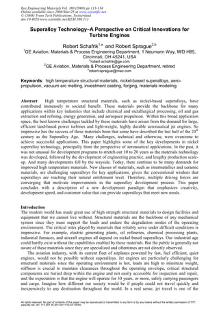
  • 14. Zone 4 is the regime of exceptionally deleterious defects that randomly develop at extremely low frequency, such as one or fewer occurrences per million opportunities. An example of a material in Zone 4 was the AISI 52100 VIM bearing steel that contained small amount of exogenous oxide inclusions that led to infant mortality of a few percentage of bearings. These defects are usually difficult to eliminate, or minimize, through process changes because they occur so infrequently that determining the benefit of a change requires massive sample sizes over long time spans. Rigorous attention to control at each process step is crucial in preventing the root cause. In the ideal case, an entirely new process would mitigate or avoid the root cause that produced the defect. Heavy reliance on NDE helps to uncover these defects, and remove the defective material from further processing. Life Prediction. Jet engine structural elements are necessarily designed to be as light weight as possible. Engines typically do not have redundant load paths that can carry the load in case one part of the structure fails. Also, engine testing is quite expensive, and in any case, cannot fully simulate 30-40 years of in-service experience. Therefore, engine designers rely extensively on the ability to estimate the life of the different parts in the engine based on knowledge of the material properties, the thermal history the part will experience, knowledge of the underlying degradation mechanisms, mechanical loads, effect of stress concentrating features, etc. For instance, low cycle fatigue (LCF) is one of the primary failure modes that limits component life within the engine. In most cases, LCF occurs at strain concentrations, such as disk bolt holes and blade retention slots, that are subject to transient loads in excess of the local yield strength even though detectable dimensional change, prohibited by the surrounding mass, does not occur. A cornerstone of life prediction are baseline material properties than can be assured. Therefore, design engineers do not use the average property values in their analyses: they typically use the properties at the 95 percent confidence level that 99 percent of the data points will be above this minimum value. This approach provides conservatism that is necessary to address the range in properties associated with process variation without compromising design intent. Motivation for Advanced Materials in Jet Engines. In aero-propulsion applications, a case can be made for slow adoption of new structural materials since the consequence of making a poor choice can be quite deleterious. Thus the anticipated benefit of a new material, or an existing material that is processed differently to enhance a particular property, must be significant. There are at least three prime driving forces spurring the development of new structural materials, counteracting a conservative “stand pat” management policy. Traveling public’s expectation for continued improvement in jet engine safety through higher reliability in mechanical components. Competitive pressure for improved engine performance, such as increased thermodynamic efficiency for reduced fuel burn. Need for lighter weight structures that allow airlines to carry more passengers and cargo further distances. A widely used indicator of the technological state of propulsion jet engines is the ratio of engine output thrust to engine weight, the thrust:weight ratio. Whittle's original 840-pound engine generated thrust:weight of approximately 1.5:1 and could operate for a few hundred hours at most. Current commercial jet engines have thrust:weight of 4:1 to 8:1, and advanced engines are targeting higher ratios. These advances are due, in no small measure, to significant improvements in both materials and processes that enabled improved designs. Using thermodynamic analysis, B. Koff suggested that the inherent efficiency of a turbine engine, compared to the ideal, could be estimated by calculating the power generated by the core of the engine as a function of turbine rotor inlet temperature, T4, which is the highest temperature in the engine. Furthermore, Koff pointed out that compressor discharge temperature, T3, limits the pressure ratio and hence the flight speed. The result is depicted in Fig. 6.[18] When data from the earliest jet engines through the more recent ones are plotted, it is apparent that engines still have 126 Innovation in Materials Science
  • 15. significant opportunity for improvement to edge closer to ideal efficiency. Since both T3 and T4 are constraints, this plot emphasizes the benefits of gains in materials or improved cooling methods to allow further increases in turbine power. Therefore, considerable advancements still can be made to aero-engines. And materials will necessarily play an important role. But other technologies are also essential: acoustics, aerodynamics, combustion science, design technology, and heat transfer, for example. Engine developers will invest in the development of those technologies that can deliver the greatest benefit. Thus materials and process technologies must compete with these technologies for resources to gain the opportunity to provide improvements. A Path to Acceleration Innovation The historical timeline for material development has been quite lengthy, and was rather constant for some time. However, product development timelines have continued to decrease. Therefore, within the jet engine technology field, materials development has not kept pace. However, there are powerful driving forces motivating the search for better materials and for reduced timelines to incorporate these new materials into critical applications in the engine. The emerging paradigm involves tight linkage between the materials and the engineering design community, using the metric of “customer value” as the guide for selecting technologies. Material Development Timeline. In the past, materials were developed to be “better” than existing materials. The predominate expectation was that design engineers would soon specify the superior material, and applications for the material would be forthcoming. To a large degree, this approach worked. Given the long time required for materials development, design engineers could not accurately foresee what material would be needed in 10 years since they were focused on engineering the next generation engine, not the generation afterwards. And often the materials developers were right in their assessments–they correctly anticipated the need for higher temperature capable superalloys. Table 2 contains typical times required to fully develop and implement a new material for an aircraft engine application. Very few tools existed to help alloy developers design the chemistry of alloys. (An early exception was the development of models based on Linus Pauling’s Electron Vacancy Theory that provided an estimate of the susceptibility of superalloy chemistries to Fig. 6. Turbine Engine Thermodynamic Efficiency Key Engineering Materials Vol. 380 127
  • 16. deleterious TCP precipitation.) Therefore trial and error, with much testing, was the rule rather than the exception. For instance, General Electric’s René 41 superalloy was so named because a usable alloy was discovered on the 41st iteration after nearly a decade of research. A new class of structural material, intermetallic TiAl, required 30 years for development. Table 2. Historical Materials Development Timelines [19] Case I. Modification of an existing material for a non-structural critical component • Approximately 2-3 years Case II. Modification of an existing material for a critical structural component • Up to 4 years Case III. New material within an existing alloy system • Up to 10 years -Includes time to define the chemistry and the processing details -Supply chain already exists Class IV. New material class with no prior experience • Up to 20 years, and beyond -Includes the time to develop design practices that fully exploit the performance of the new material class -Establish a viable supply chain While materials developers continued along this Edisonian path, other disciplines, such as aerodynamics and mechanical engineering, were making strides in computer modeling. Finite element modeling, computational fluid dynamics and heat transfer analysis, to name a few design technologies, were increasingly able to perform design iterations by computer analysis rather than building subscale models and measuring data. For instance, the new composite fan blade shape for the GE90-115B was designed using 3D aero code in 72 iterations over the course of a few weeks. If that work followed the historical materials development paradigm, 72 subscale models would have had to been built and tested in a wind tunnel over the course of several years at great expense. New engine programs are completed within 30 months, aiming toward 24 months. Materials development requires several times this time period. In essence, design technology has out-paced materials development technology. As design tools become more sophisticated, they demand more material behavior data through-out the temperature range of interest. Typical property data includes: elastic constants, creep and stress rupture, yield and ultimate tensile strength, ductility, strain-rate sensitivity, high cycle and low cycle fatigue behavior, fracture toughness, impact resistance, and crack growth rate. This range of mechanical property data is critical to determining if a given material can satisfactorily perform in a targeted application. Obtaining this data for a new material is often an expensive, lengthily process. Too often materials development efforts have focused on optimizing one of these properties, only to later determine that low performance in another property renders the material unsuitable for the application. Achieving the right balance in properties is essential to identifying suitable candidate high temperature structural materials. Plus, once a new material looks interesting from a design analysis standpoint, further analysis must be done to assess producibility: Knowledge of the phase diagram, recrystalization temperature, machinability, weldability, forgeability, and so on, rise to paramount importance. Consequently, quite a bit of time and effort can be expended to collect all the required data, only to discover that the proposed material solution has serious limitations, is not quite good enough to supplant an existing solution, or is otherwise is not attractive enough for implementation. New Material Development Paradigm. Material developers must rise to the challenge of competition for technology development resources among all the different opportunities to improve 128 Innovation in Materials Science
  • 17. turbine engines. This competition occurs in two levels: materials RD must compete for funding priority with other technology areas, and various material solutions compete among themselves in a quest for the best alternative. In order to be successful, a materials solution must have a credible “value case” in which the cost of development and implementation is favorably compared with the expected benefit for a given application. Therefore, prioritization of resources requires a credible value case analysis that includes the cost of implementation, which can be considerable for materials technologies, presenting a significant barrier for adoption of new materials and processing technology. This paradigm is significantly different than the historic approach, which was materials developer centric. This new paradigm is system engineering centric, requiring that proposed materials capability be aligned to design requirements, and critical-to-success metrics identified that can focus resources to assure implementation success. This process is illustrated in Figure 7. The top portion depicts the stages of technology creation; the bottom half depicts the stages of product creation. For technology creation, the investment is typically on the order of US$1 million to establish feasibility (Technical Tollgate 3, TTG3), and increases by an order of magnitude to demonstrate capability (TT6), and can increase by another order of magnitude to mature the technology (TTG9) since required supply chain investment costs alone can be on the order of US$100 million for a new technology if a new supporting industrial base must be established. Under this new paradigm, materials developers can still exercise a great deal of creativity to establish the feasibility of a new material. A major difference from the previous development regime: feasibility is determined with respect to the needs of a particular component, rather than a generic set of requirements. Considering the engine development process, there can be engine demonstrator platforms in operation that prove out various technologies, such as a high efficiency fan, before a formal product creation effort is launched. These platforms explore the realm of the possible, without being constrained to meet specific requirements. Once a decision is made to launch a product however, specific criteria are established that the engine must meet. The product creation process has 3 key development stages, each of which is defined by a tollgate process that measures progress toward the set of requirements: determine feasibility (Tollgate 3, TG3), demonstrate product capability (TG6), and mature the product for entry into service (TG9). The cost to create a new centerline engine can be US$1 to $2 billion, or more, to proceed through to TG9. Ideally, a technology targeted at an application in the engine will be at TTG9 when the engine development program is at TG6. This allows for the new technology to be inserted into the engine with a minimum of unplanned, costly surprises. Of course, there is on-going communication much earlier than TG6 between the materials development efforts and the engine development program. This interaction is important to insure that the materials effort continues to be targeted at the right application(s), that the required design practices for the new technology are being developed, Feasibility Demonstration Maturation TRL3 TRL6 TRL9 Feasibility Demonstration Maturation TG3 TG6 TG9 Product Creation—$Billion Dollar Commitment •Initial evaluation- lab scale •Estimates of key characteristics •Sub-scale demonstration •Components produced to prelim specs •Production windows estim •Process capability fully established Production specifications in place Supply chain established •All necessary property data obtained •Computer simulations, sub- scale testing of concepts •Performance estimates made •Full scale testing •Product performance validated •Mature Technologies •Production components designed •Product engines certified •Products enter service Technology Creation— $Million Commitment Demonstrator Programs Component Design Only Applies Mature Technology Feasibility Demonstration Maturation TRL3 TRL6 TRL9 Feasibility Demonstration Maturation Feasibility Demonstration Maturation TRL3 TRL3 TRL6 TRL6 TRL9 TRL9 Feasibility Demonstration Maturation TG3 TG6 TG9 Feasibility Demonstration Maturation Feasibility Demonstration Maturation TG3 TG3 TG6 TG6 TG9 TG9 Product Creation—$Billion Dollar Commitment •Initial evaluation- lab scale •Estimates of key characteristics •Sub-scale demonstration •Components produced to prelim specs •Production windows estim •Process capability fully established Production specifications in place Supply chain established •All necessary property data obtained •Computer simulations, sub- scale testing of concepts •Performance estimates made •Full scale testing •Product performance validated •Mature Technologies •Production components designed •Product engines certified •Products enter service Technology Creation— $Million Commitment Demonstrator Programs Demonstrator Programs Component Design Only Applies Mature Technology Fig. 7. Technology and Product Development Stages and Interaction Key Engineering Materials Vol. 380 129
  • 18. appropriate scalability and processability issues are being addressed, and inspectability methods and process limits are underway. As the technology and product development programs progress in parallel, better definition of costs and benefits of the technology can be made, reinforcing the business case. This is important not only for the technologist, but also for the supplier base that requires lead-time to industrialize the new technology. The material development process is complicated by the fact that within the materials field, various materials approaches vie for development resources. This is graphically illustrated in Fig. 8, which maps various material families on a plot of Strength versus Temperature. Nickel superalloys are being challenged on the low temperature end by titanium and intermetallic titanium aluminides, and on the high temperature end by ceramic matrix composite (CMC) materials and refractory metal intermetallics, such as niobium silicides. From an engine design engineer perspective, having material options is desirable since it increases the opportunity to achieve the best match of material properties to design requirements. From a material developer viewpoint, the opportunity to present leading edge ideas as candidates to satisfy a defined need is also rewarding. This competitive approach opens the door to new ideas, and overcoming inertia and stagnation in materials technology. For example, superalloy airfoils are well established in the turbine section of the engine. But great strides are being made in the development of ceramic matrix composite airfoils; the feasibility of using CMCs in this application is currently being established. Superalloy airfoil developers are responding to this challenge by an innovative multi-prong initiative that includes advancement in airfoil substrate materials, heat transfer technology, and airfoil coatings that allow longer operation at higher temperatures. Thus, the competition between these material systems has led to advancements across a broad front. The “fundamental challenge” is to drastically reduce the development time for new materials and processes without adding development risk. The superalloy development sequence used during the past 50 years could be characterized, for the most part, as sequential, as shown in Fig 9. New materials were invented, and then a long process ensued to find a specific application, fill in all the other required details and establish a supply chain. The current process avoids many of the pitfalls of the past, using integrated teams that employ analysis tools, that include materials and process modeling combined with design of critical experiments. Materials modeling tools that effectively combine heuristic and fundamental knowledge can rapidly provide realistic estimates of material properties, providing an important element in the quest to Titanium Alloys TiAl Alloys Superalloys Refractory Metals and Intermetallics Mg Al Single Crystal Superalloys Specific Strength (MPa/(Mg/m 3 )) 50 100 150 200 250 Temperature (ºC) 200 700 1200 1700 CMC Titanium Alloys TiAl Alloys Superalloys Refractory Metals and Intermetallics Mg Al Single Crystal Superalloys Specific Strength (MPa/(Mg/m 3 )) 50 100 150 200 250 Specific Strength (MPa/(Mg/m 3 )) 50 100 150 200 250 Temperature (ºC) 200 700 1200 1700 CMC CMC Fig. 8. Material Options [20] Development Iterations Make It ⇒Test It Improve It ⇒ Test It Cost Reduce It ⇒ Test It Materials Development Design Practice Development Real Component Application Production Scale-Up Committed Component Application Development Iterations Make It ⇒Test It Improve It ⇒ Test It Cost Reduce It ⇒ Test It Materials Development Design Practice Development Real Component Application Production Scale-Up Committed Component Application Fig. 9. Superalloy Development Sequence—Past 130 Innovation in Materials Science
  • 19. address the fundamental challenge. A representative example of how different models can be linked together to provide an estimate of material properties is depicted in Fig. 10. The current development approach is depicted in Fig 11. All together, it is resulting in considerable reduction in development time and resources. But progress is not as rapid as it could be since the teams are not fully integrated for several reasons that include: • The tools that are being used across the teams are not standardized or not fully integrated. • Legal issues regarding contractual terms and conditions, such as protection of proprietary data, retard progress. A complicating factor is the reality that team members can also be competitors on other projects, and thus there is a reluctance to share best ideas between potential and actual competitors. For instance, cooperating partners strive to add legal protection against possible future misuse of proprietary information on the part of the other team members. • Different reward structures exist among industry, university, and government laboratory team members. This results in differing priorities that can affect timely completion of critical tasks. Fig. 10. Material Models Development Iterations Design It ⇒ Analyze It Make It ⇒ Test It Optimize Cost Reduce It ⇒ Test It Materials Development Design Practices Production Scale-Up Integrated Teams Manufacturing Development Iterations Design It ⇒ Analyze It Make It ⇒ Test It Optimize Cost Reduce It ⇒ Test It Materials Development Design Practices Production Scale-Up Integrated Teams Manufacturing Fig. 11. Superalloy Development Sequence—Current Practice Key Engineering Materials Vol. 380 131
  • 20. The idealized goal for a fully integrated team is depicted in Fig 12; even though it may not be possible to achieve the ideal, it is a goal worth striving for. Summary The first 60 years of jet-powered flight has been quite exciting, far exceeding expectations of most experts. Materials and process advancements have played a key role in this adventure. The future is unknown, and predictions are inherently risky. However, the next 50 years of jet engines is sure to be as equally exciting, and there can be little doubt that progress in materials and processes will be pacing the advancements. The history of materials and process development for jet engines contains several prominent themes that will continue to be major factors. • Turning advanced design concepts into reality is often enabled by new materials and processes. Materials and design engineers have both benefited from, and enjoyed, the ongoing game of leapfrog. • The high introductory cost of a new material or process can be offset by a compelling mission benefit, even in a cost-constrained business environment. • The challenge of avoiding exceptionally deleterious defects that occur at very low frequencies significantly influences the development and application of high integrity structural materials. • Each incremental gain in an alloy property is usually tempered by some corresponding debit. A key aspect of the development strategy involves determining the benefit, and understanding the debit, of each change. Therefore, providing balanced material properties throughout the different stress and temperatures regimes is critical to successful material development. • A new class of structural materials, such as ceramic matrix composites and intermetallics, must vie for development resources with existing materials. This competitive process adds vibrancy and overcomes stagnation in materials technology. Singl e It er at ion Optimized Analysis ⇒Validate It Materials Development Design Practice Production Scale-Up Integrated Teams Manufacturing Integrated, Seamless Computational Environment Singl e It er at ion Optimized Analysis ⇒Validate It Materials Development Materials Development Design Practice Design Practice Production Scale-Up Integrated Teams Manufacturing Manufacturing Integrated, Seamless Computational Environment Fig. 12. Superalloy Development Sequence—Ideal 132 Innovation in Materials Science
  • 21. • Usable material properties are governed by the type and frequency of defects arising from processing, not by the average property values that are determined by the chemistry and microstructure of the alloy. The Grand Challenge for the materials development community is to mature new materials technology at a faster rate than the long drawn-out historical timeline. This accelerated schedule provides closer alignment to the product development cycle. Consequently, materials technology will be positioned to contribute significantly to the quest for improved aero-turbine engine performance. The key elements of this new materials development paradigm include: • The new paradigm is system engineering centric, requiring that proposed materials capability be aligned to design requirements, and critical-to-success metrics identified that can focus resources to assure implementation success. This requires tight linkage between materials technologists and the engineering design community, using the metric of “customer value” to guide the final selection of the technologies. This linkage insures that the appropriate engineering design practices are in place to allow usage of the material. • Under this new paradigm, materials developers are encouraged to exercise creativity in establishing the feasibility of a new material. However feasibility is determined with respect to the needs of a particular component, rather than a generic set of requirements. These needs include prediction of component lifetime with respect to all possible material degradation modes in the anticipated service environment. • Materials modeling and simulation are becoming essential tools. Material innovation requires exploring multiple paths to find the optimum solution. Laborious physical trial-and- error experiments aimed at finding the appropriate solution is too lengthily and costly to be the primary method of investigation. Computer-based analyses, followed by targeted physical experiments, can quickly determine feasibility and guide the scale-up effort for the desired materials solution. References [1] A Review of United States Air Force and Department of Defense Aerospace Propulsion Needs, National Academy Press: Washington, DC, 2006, p. 208-209 [2] http://www.greatachievements.org/?id=3809, accessed 19April2007 [3] H.L. Eiselstein, “Age-Hardenable Nickel Alloy,” US Patent 3,667,938; June 6, 1972 [4] R.E. Schafrik, D.D. Ward, and J.R. Groh, “Application of Alloy 718 in GE Aircraft Engines: Past, Present and Next Five Years,” Proceedings of the Fifth International Symposium on Superalloys 718, 625, 706, and Derivatives, TMS, 2001, pg.3 [5] R.E. Schafrik, D.D. Ward, and J.R. Groh, op cit, pp.1-13. [6] R.L. Kennedy, Allvac® 718PlusTM , Superalloy for the Next Forty Years, Proceedings of the Sixth International Symposium on Superalloys 718, 625, 706, and Derivatives, TMS, 2005, pp.1-14 [7] E.A. Ott, J. Groh, H. Sizek, Metals Affordability Initiative: Application of Allvac 718Plus® for Aircraft Engine Static Structural Components, Proceedings of the Sixth International Symposium on Superalloys 718, 625, 706, and Derivatives, TMS, 2005, pp.35-46 [8] R.Schafrik; L. Christodoulou; and J.C. Williams, “Collaboration Is an Essential Part of Materials Development”, JOM, The Minerals, Metals, Materials Society (TMS), Vol 57, No. 3, March 2005, pp14-16. [9] J.J. Shirra, P.L Reynolds, E.S. Huron, K.R. Bain, D.P. Mourer; Effect of Microstructure on the 649ºC Properties of Advanced P/M Superalloy Disk Materials, TMS Superalloys 2004, pp. 341- 350. Key Engineering Materials Vol. 380 133
  • 22. [10] E.S Huron, K.R. Bain, D.P. Mourer, J.J. Schirra, P.L. Reynolds, and E.E. Montero; The Influence of Grain Boundary Elements on Properties and Microstructures of P/M Nickel Base Superalloys, TMS Superalloys 2004, pp.73-81 [11] M.C. Hardy, B. Zirbel, G. Shen, and R. Shankar; Developing Damage Tolerance and Creep Resistance in a High Strength Nickel Alloy for Disc Applications, Superalloys 2004, pp. 83-90 [12] S. Walston, A. Cetel, R. MacKay, K. O’Hara, D. Duhl, R. Dreshfield; Joint Development of a Fourth Generation Single Crystal Superalloy, Superalloys 2004, pp. 15-24 [13] Y. Koizumi, T. Kobayashi, T. Yokokawa, Z. Jianxin, M. Osawa, H. Harada, Y. Aoki, and M. Arai; Development of Next-Generation Ni-Base Single Crystal Superalloys, Superalloys 2004, pp. 35-43 [14] J. Ogando, Here Comes the Factory of the Future, Design News, Vol 62, no.11, 08.13.07, pp62-66 [15] Hohmann and S. Pleier, “Production Methods and Applications for High-Quality Metal Powders and Sprayformed Products, Acta Metall. Sin. (Engl. Lett.) Vol 18 No 1, pp 15-23, Feb 2005 [16] M.D. Barratt, Z. Shi, R.M. Ward, P.S. Grant, M.H. Jacobs, and J. Mi; Microstructure, Macrostructure, and Modeling of the Centrifugal Spray Deposition of Large Diameter Superalloy Preforms, TMS, Superalloys 2004, pp.563-570 [17] J.C. Williams, Progress in Aero-Propulsion: The Role of Materials, presentation at ASM Aeromat, Jun 2003 (personal communication) [18] A Review of United States Air Force and Department of Defense Aerospace Propulsion Needs, National Academy Press: Washington, DC, 2006, pp 207-208. Reprinted by permission from the National Academies Press, Copyright 2006, National Academy of Sciences. [19] Accelerating Technology Transition: Bridging the Valley of Death for Materials and Processes in Defense Systems, National Academy Press: Washington, DC, 2004, p.16 [20] Adapted from A Review of United States Air Force and Department of Defense Aerospace Propulsion Needs, op cit, Fig. 6-6, p. 210 134 Innovation in Materials Science
  • 23. Innovation in Materials Science 10.4028/www.scientific.net/KEM.380 Superalloy Technology - A Perspective on Critical Innovations for Turbine Engines 10.4028/www.scientific.net/KEM.380.113