The document summarizes quality assurance and quality control procedures implemented at Larsen & Toubro for infrastructure projects. It discusses establishing a Project Quality Plan to meet contract terms and adherence to ISO standards. Key tests described include consistency, initial and final setting time for cement. Proper procedures are followed for sample preparation, conducting tests using apparatus like Vicat and reporting results. Quality is a priority and systems ensure control at all construction stages as per international standards.


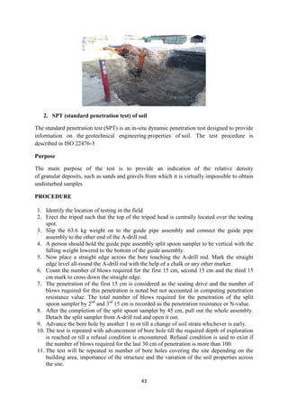
![19
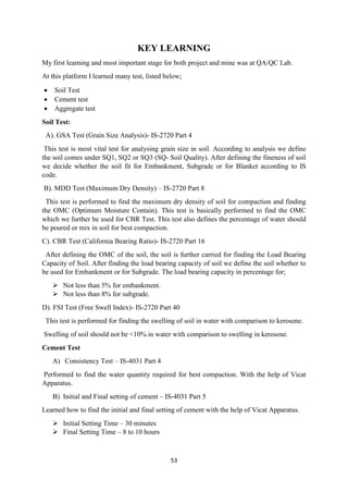
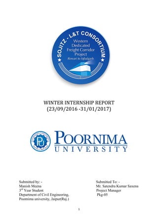
5. Fineness modulus is obtained by adding cumulative percentage of aggregates retained
on each sieve and dividing the sum by 100.
REPORTING OF RESULTS
The results should be calculated and reported as:
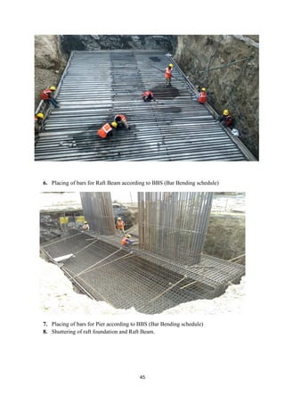
1. the cumulative percentage by weight of the total sample
2. the percentage by weight of the total sample passing through one sieve and retained
on the next smaller sieve, to the nearest 0.1 percent.
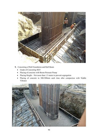
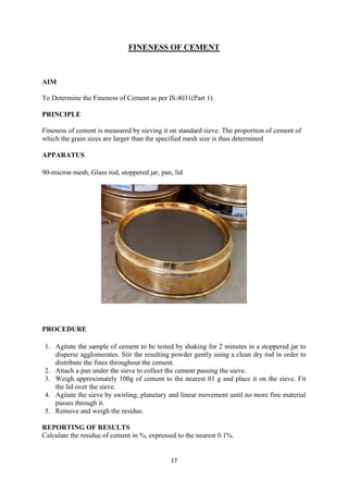
WATER ABSORPTION
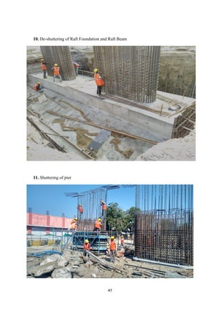
AIM
To determine the water absorption of coarse aggregates as per IS: 2386 (Part III) - 1963.
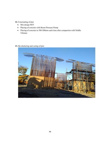
APPARATUS
• Wire basket - perforated, electroplated or plastic coated with wire hangers for
suspending it from the balance
• Water-tight container for suspending the basket
• Dry soft absorbent cloth - 75cm x 45cm (2 nos.)
• Shallow tray of minimum 650 sq.cm area
• Air-tight container of a capacity similar to the basket
• Oven sample A sample not less than 2000g should be used.
PROCEDURE
1. The sample should be thoroughly washed to remove finer particles and dust, drained
and then placed in the wire basket and immersed in distilled water at a temperature
between 22 and 32oC.
2. After immersion, the entrapped air should be removed by lifting the basket and
allowing it to drop 25 times in 25 seconds. The basket and sample should remain
immersed for a period of 24 + 1⁄2 hrs. afterwards.
3. The basket and aggregates should then be removed from the water, allowed to drain
for a few minutes, after which the aggregates should be gently emptied from the
basket on to one of the dry clothes and gently surface-dried with the cloth,
transferring it to a second dry cloth when the first would remove no further moisture.
4. The aggregates should be spread on the second cloth and exposed to the atmosphere
away from direct sunlight till it appears to be completely surface-dry. The aggregates
should be weighed (Weight 'A').
5. The aggregates should then be placed in an oven at a temperature of 100 to 110oC for
24hrs. It should then be removed from the oven, cooled and weighed (Weight 'B').
REPORTING OF RESULTS
Water absorption = [(A-B)/B] x 100%](https://image.slidesharecdn.com/manishmeena-170411135409/85/summer-training-report-in-L-T-construction-19-320.jpg)
![21
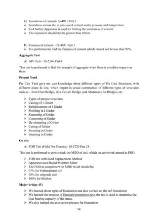
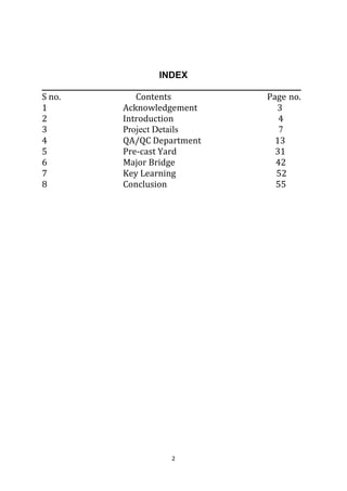
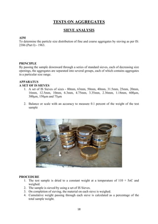
PROCEDURE
1. The cylindrical steel cup is filled with 3 equal layers of aggregate and each layer is
tamped 25 strokes by the rounded end of tamping rod and the surplus aggregate struck
off, using the tamping rod as a straight edge.
2. The net weight of aggregate in the cylindrical steel cup is determined to the nearest gram
(WA) and this weight of aggregate is used for the duplicate test on the same material.
3. The cup is fixed firmly in position on the base of the machine and the whole of the test
sample is placed in it and compacted by a single tamping of 25 strokes of tamping rod.
4. The hammer is raised until its lower face is 380 mm. above the upper surface of the
aggregate in the cup, and allowed to fall freely onto the aggregate 15 times, each being
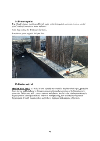
delivered at an interval of not less than one second.
5. The crushed aggregate is removed from the cup and sieved on 2.36 mm. IS sieve until no
further significant amount passes in one minute.
6. The fraction passing the sieve is weighed to an accuracy of 0.1 g (WB)
CALCULATION
The ratio of the weight of fines formed to the total sample weight in each test is to be
expressed as a percentage, to the first decimal place.
Aggregate impact Value = (WB / WA) × 100
AGGREGATE FLAKINESS INDEX VALUE
OBJECTIVE
For determination of flakiness index of coarse aggregate, where the size of the coarse
aggregate is larger than 6.3mm
REFERENCE STANDARDS
IS: 2386 (Part I) – 1963 – Method of test for aggregates for concrete (Part I) Particle size and
shape.
EQUIPMENT & APPARATUS
Thickness gauge
Sieves [63, 50, 40, 31.5, 25, 20, 16, 12.5, 10 & 6.3mm]
Balance [0-10 kg]](https://image.slidesharecdn.com/manishmeena-170411135409/85/summer-training-report-in-L-T-construction-21-320.jpg)
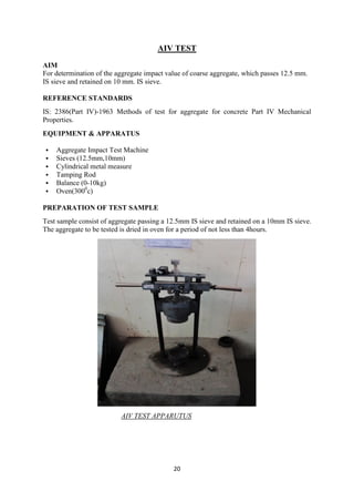
![23
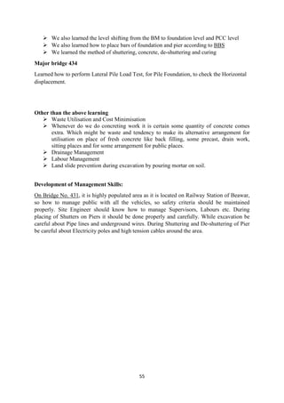
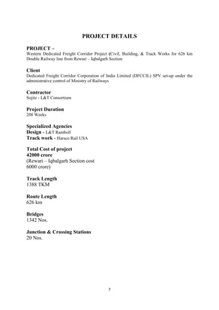
EQUIPMENT & APPARATUS
Los Angeles machines
Sieves (1.70mm)
Cylindrical metal measure
Tamping Rod
Balance (0-10kg)
Oven (3000
c)
Test sample is dried in oven for a period of four hours at a temperature of 100 to 110C
PROCEDURE
1. The required weight of test sample is selected conforming to one of the grading
mentioned in Table II of IS: 2386 (Part IV) – 1963.
2. The test sample and the abrasive charge is to be placed in the machine and rotated at a
speed of 20 to 33 rev/min.
3. For grading A, B, C & D [as per Table II of IS: 2386 (Part IV)- 1963] the machine is to
be rotated for 1000 revolutions.
4. At the completion of the test, the material is discharged from the machine and separation
of the sample is made on 1.70 mm. IS sieve.
5. The material coarser than 1.70 mm. IS sieve is washed, dried accurately weighed to the
nearest gram.
REPORT
The mean of the two results is reported to the nearest whole number as the aggregate abrasion
value of the tested material.](https://image.slidesharecdn.com/manishmeena-170411135409/85/summer-training-report-in-L-T-construction-23-320.jpg)
![24
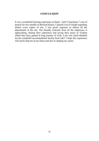
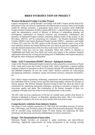
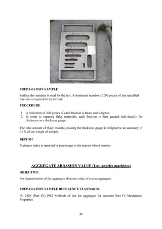
SOIL TEST
LIGHT/STANDARD PROCTOR COMPACTION TEST OF SOIL
OBJECTIVE
For determination of the relation between the water content and the dry density of soils using
light compaction.
REFERENCE STANDARD
IS: 2720(Part 7)-1980- Methods of test for soils: Determination of water content-dry density
relation using light compaction.
EQUIPMENTS & APPARATUS
Cylindrical mould & accessories [volume = 1000cm3
]
Rammer [2.6 kg]
Balance [1g accuracy]
Sieves [19mm]
Mixing tray
Trowel
Graduated cylinder [500 ml capacity]
Metal container
PREPARATION SAMPLE
Obtain a sufficient quantity (10 kg) of air-dried soil and pulverize it. Take about 5 kg of soil
passing through 19mm sieve in a mixing tray.
PROCEDURE
1. 5 Kg. of soil is taken and the water is added to it to bring its moisture content to about 4
% in coarse grained soils and 8% in case of fine grained soils with the help of graduated
cylinder
2. Then the moist soil in the mould is compacted in three equal layers, each layer being
given 25 blows from the 4.89Kg rammer dropped from a height of 310 mm. above the
soil.
3. The extension is removed and the compacted soil is levelled off carefully to the top of
the mould by means of a straight edge.
4. Then the mould and soil is weighed to the nearest 1 gm.
5. The soil is removed from the mould and a representative soil sample is obtained water
content determination.
6. Steps 3 to 6 are repeated after adding suitable amount of water to the soil in an
increasing order.](https://image.slidesharecdn.com/manishmeena-170411135409/85/summer-training-report-in-L-T-construction-24-320.jpg)
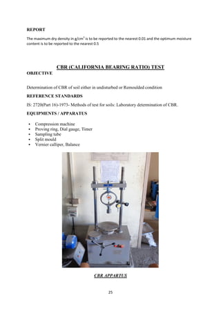
![26
PROCEDURE
1. The mould containing the specimen with the base plate in position but the top face
exposed is placed on the lower plate of the testing machine.
2. Surcharge weights, sufficient to produce an intensity of loading equal to the weight of
the base material and pavement is placed on the specimen.
3. To prevent upheaval of soil into the hole of the surcharge weights, 2.5 kg annular weight
is placed on the soil surface prior to seating the penetration plunger after which the
remainder of the surcharge weight is placed.
4. The plunger is to be seated under a load of 4 kg so that full contact is established
between the surface of the specimen and the plunger.
5. The stress and strain gauges are then set to zero. Load is applied to the penetration
plunger so that the penetration is approximately 1.25 mm per minute.
6. Readings of the load are taken at penetrations of 0.0, 0.5, 1.0, 1.5, 2.0, 2.5, 4.0, 5.0, 7.5,
10.0 and 12.5 mm.
7. The plunger is then raised and the mould detached from the loading equipment.
REPORT
The CBR values are usually calculated for penetration of 2.5 mm and 5 mm. The CBR value
is reported correct to the first decimal place
FREE SWELL INDEX TEST OF SOIL
OBJECTIVE
For determination of free swell index of soils
REFERENCE STANDARD
IS: 2720(Part 40)-1985- Methods of test for soils: Determination of free swell index of soil.
EQUIPMENT / APPARATUS
Oven (1050
C to 1100
C, min)
Balance (0.01g accuracy)
Sieve [425 microns]
Graduated glass cylinder [100ml capacity]
PREPARATION SAMPLE
The soil passing 425-micron sieve is used in this test.
PROCEDURE
1. Two no. of 10 g oven dried soil specimens passing through 425 microns IS sieve is
taken.](https://image.slidesharecdn.com/manishmeena-170411135409/85/summer-training-report-in-L-T-construction-26-320.jpg)
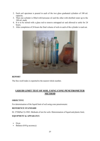
![28
Sieve [425 microns]
Cone penetrometer
PREPARATION SAMPLE
After receiving the soil sample, it is dried in air or in oven (maintained at a temperature of
600
C). If clods are there in soil sample, then it is broken with the help of wooden mallet.
SOIL PENTROMETER
PROCEDURE
1. About 150 gm. of air dried soil from thoroughly mixed portion of material passing 425
microns IS sieve is obtained.
2. Distilled water is mixed to the soil thus obtained in a mixing disc to form a uniform
paste.
3. Then the wet soil paste is transferred to the cylindrical cup of cone penetrometer
apparatus, ensuring that no air is trapped in this process.
4. Finally, the wet soil is levelled up to the top of the cup and placed on the base of the
cone penetrometer apparatus.
5. The penetrometer is so adjusted that the cone point just touches the surface of the soil
paste in the cup and the initial ready is to be taken.
6. The vertical clamp is then released allowing the cone to penetrate into soil paste under
its own weight for 5 seconds. After 5 seconds the penetration of the cone is noted to the
nearest millimetre.
7. The test is repeated at least to have four sets of values of penetration in the range of 14 to
28 mm.
8. The exact moisture content of each trial is determined
REPORT
The liquid limit is to be reported to the nearest first decimal place.](https://image.slidesharecdn.com/manishmeena-170411135409/85/summer-training-report-in-L-T-construction-28-320.jpg)