SlideShare a Scribd company logo
1 of 77
1
Theories of Failure
Theories of Failure
1. Fracture of the material of which the member is made. This type
of failure is the characteristic of brittle materials.
2. Initiation of inelastic (Plastic) behavior in the material. This type
of failure is the one generally exhibited by ductile materials.
When an engineer is faced with the problem of design using a specific
material, it becomes important to place an upper limit on the state of stress
that defines the material's failure. If the material is ductile, failure is usually
specified by the initiation of yielding, whereas if the material is brittle it is
specified by fracture.
2
These modes of failure are readily defined if the member is subjected to a
uniaxial state of stress, as in the case of simple tension however, if the
member is subjected to biaxial or triaxial stress, the criteria for failure
becomes more difficult to establish.
In this section we will discuss four theories that are often used in
engineering practice to predict the failure of a material subjected to a
multiaxial state of stress.
A failure theory is a criterion that is used in an effort to predict the
failure of a given material when subjected to a complex stress
condition.
3
i. Maximum shear stress (Tresca) theory for ductile materials.
ii. Maximum principal stress (Rankine) theory.
iii.Maximum normal strain (Saint Venan’s) theory.
iv. Maximum shear strain (Distortion Energy) theory.
Several theories are available however, only four important
theories are discussed here.
4
Maximum shear stress theory for Ductile Materials
The French engineer Tresca proposed this theory. It states that a member
subjected to any state of stress fails (yields) when the maximum shearing
stress (τmax)in the member becomes equal to the yield point stress (τy)in a
simple tension or compression test (Uniaxial test). Since the maximum shear
stress in a material under uniaxial stress condition is one half the value of
normal stress and the maximum normal stress (maximum principal stress) is
max, then from Mohr’s circle.
2
max
max

 
5
6
If both of principal stresses are of the same sign
tension compression then
σ1 <σy (4)
σ2 <σy (5)
In case of Biaxial stress state
)
3
(
2
2
)
2
(
2
2
2
1
2
1
max
2
1
min
max
max











y
y
y













7
A graph of these equation is given in the figure. Any given state of
stress will be represented in this figure by a point of co-ordinate
1 and 2 where 1 and 2 are two principal stresses. If these point
falls within the area shown, the member is safe and if outside then
member fails as a result of yielding of material. The Hexagon
associated with the initiation of yield in the member is known as
“Tresca Hexagon”. (1814-1885). In the first and third quadrant 1
and 2 have the same signs and
8
max is half of the numerically larger value of principal stress 1
or 2. In the second and fourth quad, where 1 and 2 are of
opposite sign, max is half of arithmetical sum of the two 1 and
2. In fourth quadrant, the equation of the boundary or limit
(yield/boundary stress) stress line is
1 - 2 = y
And in the second quadrant the relation is
1 - 2 = -y
9
y


 

 2
1
y

 

1
y

 
1
y

 
2
y


 
 2
1
y

 

2
10
Problem 01
The solid circular shaft in Fig. (a) is subject to belt pulls at each end
and is simply supported at the two bearings. The material has a yield
point of 36,000 Ib/in2• Determine the required diameter of the shaft
using the maximum shear stress theory together with a safety factor of
3.
11
400 + 200 lb
200 + 500 lb
12
0
42800
64
2
4200
.
4200
6
700
.
3600
6
600
64
2
3
4
4













y
x
x
B
x
d
d
d
in
lb
Mc
in
lb
M
d
I
d
c
I
Mc






13
in
lb
OR
in
lb
T
d
d
d
J
Tr
xy
xy
.
4800
24
200
24
)
200
400
(
.
4800
16
300
16
)
200
500
(
480
,
24
32
2
4800
3
4



















3
480
,
24
d
xy 

3
800
,
42
d
x 

14
 2
2
2
1
max
2
1
2
2
2
know
we
As
xy
y
x
















 




3
36000
2
)
(
2
.
.
.
.
.
.
And
2
1
2
1
max






FOS
S
O
F
S
O
F
yield
yield
y








15
'
'
76
.
1
480
,
24
2
42800
10
36
480
,
24
2
42800
2
000
,
12
480
,
24
2
42800
2
3
000
,
36
480
,
24
2
42800
2
2
3
2
3
6
2
3
2
3
2
3
2
3
2
3
2
3
2
1



























































d
d
d
d
d
d
d
d
d


16
Problem 02
The state of plane stress shown occurs at a critical point of a steel
machine component. As a result of several tensile tests, it has been found
that the tensile yield strength is y = 250 MPa for the grade of steel used.
Determine the factor of safety with respect to yield, using (a) the
maximum-shearing-stress criterion, and (b) the maximum-distortion-
energy criterion.
17
18
SOLUTION
Mohr's Circle. We construct Mohr's circle for the given state of stress
and find
MPa
OC y
x
ave 20
)
40
80
(
)
( 2
1
2
1





 


MPa
FX
CF
R
m 65
)
25
(
)
60
(
)
(
)
( 2
2
2
2







Principal Stresses
MPa
CA
OC
a 85
65
20 






MPa
CA
OC
b 45
65
20 






a. Maximum-Shearing-Stress Criterion. Since for the grade of steel used
the tensile strength is ay = 250 MPa, the corresponding shearing stress at
yield is
MPa
MPa
Y
Y 125
)
250
(
2
1
2
1


 
 19
MPa
For m 65

 
2
.
19
.
65
125
. 

 S
F
MPa
MPa
S
F
m
Y


20
b. Maximum-Distortion-Energy Criterion. Introducing a factor of safety
into Eq. (7.26), we write
2
2
2
.









S
F
Y
b
b
a
a





For a = +85 MPa, b = -45 MPa, and y = 250 MPa, we have
      
2
2
2
.
250
45
45
85
85 









S
F

19
.
2
.
.
250
3
.
114 
 S
F
S
F
21
Comment. For a ductile material with y = 250 MPa, we have drawn the
hexagon associated with the maximum-shearing-stress criterion and the
ellipse associated with the maximum-distortion-energy criterion. The
given state of plane stress is represented by point H of coordinates a =
85 MPa and b = -45 MPa. We note that the straight line drawn through
points O and H intersects the hexagon at point T and the ellipse at point
M. For each criterion, the value obtained for F.S. can be verified by
measuring the line segments indicated and computing their ratios:
    19
.
2
.
2
.
19
. 



OH
OM
S
F
b
OH
OT
S
F
a 22
23
The solid shaft shown in Fig. 10-41a has a radius of 0.5 in. and is made
of steel having a yield stress of y = 36 ksi. Determine if the loadings
cause the shaft to fail according to the maximum-shear-stress theory
and the maximum-distortion-energy theory.
Example 10-12
Solution
The state of stress in the shaft is caused by both the axial force and the
torque. Since maximum shear stress caused by the torque occurs in the
material at the outer surface, we have
24
ksi
in
in
in
kip
J
Tc
ksi
in
kip
A
P
xy
x
55
.
16
2
/
.)
5
.
0
(
.)
5
.
0
.(
.
25
.
3
10
.
19
.)
5
.
0
(
15
4
2










The stress components are shown acting on an element of material at
point A in Fig. 10-41b. Rather than using Mohr's circle, the principal
stresses can also be obtained using the stress-transformation equations,
Eq.9-5.
2
2
2
,
1
2
2
2
,
1
)
55
.
16
(
2
0
10
.
19
2
0
10
.
19
2
2






 













 









 xy
y
x
y
x
25
= -9.55 ± 19.11
CTI = 9.56 ksi
CT2 = -28.66 ksi
Maximum-Shear-Stress Theory. Since the principal stresses have
opposite signs, then from Sec. 9.5, the absolute maximum shear stress
will occur in the plane, and therefore, applying the second of Eq. 10-27,
we have
 
36
2
.
38
36
66
.
28
56
.
9
?
2
1





 Y



26
Thus, shear failure of the material will occur according to this theory.
Maximum-Distortion-Energy Theory. Applying Eq. 10-30, we have
Using this theory, failure will not occur.
      
 
1296
1187
)
36
(
66
.
28
66
.
28
56
.
9
56
.
9
)
(
2
?
2
2
2
2
2
1
2
1








 y





27
Maximum Principal Stress theory or
(Rankine Theory)
According to this theory, it is assumed that when a member is
subjected to any state of stress, fails (fracture of brittle material or
yielding of ductile material) when the principal stress of largest
magnitude. (1) in the member reaches to a limiting value that is equal
to the ultimate normal stress, the material can sustain when subjected to
simple tension or compression.
The equations are shown graphically as
)
1
(
1 ult

  )
2
(
2 ult

 
28
ult


These equations are shown graphically if the point obtained by plotting
the values of 1 + 2 falls within the square area the member is safe.
29
It can be seen that stress co-ordinate 1 and 2 at a point in the material
falls on the boundary for outside the shaded area, the material is said to
be fractured failed. Experimentally, it has been found to be in close
agreement with the behavior of brittle material that have stress-strain
diagram similar in both tension and compression. It cab be further
noticed that in first and third quad, the boundary is the save as for
maximum shear stress theory.
Problem
A thin-walled cylindrical pressure vessel is subject to an internal
pressure of 600 lb/in2. the mean radius of the cylinder is 15in. If the
material ha a yield point of 39,000lb/in2 and a safety of 3 is employed,
30
determine the required wall thickness using (a) the maximum normal
stress theory, and (b) the Huber-von Mises-Hencky theory.
P = 600psi.
r = 15"
y = 39000psi
F.O.S = 3
t = ?
According to

c
 Circumferential stress / girth stress
where
Pr
t
c 

31
By comparing 1 = c.
Thus, According to the normal stress theory, maximum Principal stress
should be equal to yield stress/FOS i.e.
|1| ≤ ult |2| ≤ ult
f = maximum (|1|, |2|, |3| - ult = 0)
t
t
t
stress
al
lengitudin
For
t
t
c
l
c
4500
2
"
15
600
2
Pr
9000
"
15
600










32
As y = 39000psi
.
69
.
0
9000
13000
9000
3
39000
Ans
t
t
t




Problem 02:-
The solid circular shaft in Fig. 18-12(a) is subject to belt pulls at
each end and is simply supported at the two bearings. The material has
a yield point of 36,000 Ib/in2• Determine the required diameter of the
shaft using the maximum normal stress theory together with a safety
factor of 3. 33
400 + 200 lb
200 + 500 lb
34
35
0
42800
64
2
4200
.
4200
6
700
.
3600
6
600
64
2
3
4
4













y
x
x
B
x
d
d
d
in
lb
Mc
in
lb
M
d
I
d
c
I
Mc






36
in
lb
OR
in
lb
T
d
d
d
J
Tr
xy
xy
.
4800
24
200
24
)
200
400
(
.
4800
16
300
16
)
200
500
(
480
,
24
32
2
4800
3
4



















xy

yx

yx

xy

3
480
,
24
d
xy 
 3
800
,
42
d
x 

x

37
 
 2
2
2
2
2
1
2
2
2
2
xy
y
x
y
x
xy
y
x
y
x




















 











 



2
3
2
3
3
1
20
.
24446
2
42800
2
42800















d
d
d

According to maximum normal stress theory .
2
3
2
3
3
1
20
.
24446
2
42800
2
42800
3
36000
















d
d
d
ult 

38
"
48
.
1
51
.
10
10
514
.
1
10
144
10
62
.
597
10
96
.
457
2
10
92
.
915
10
144
20
.
24446
2
42800
2
42800
12000
6
6
9
6
6
6
6
6
3
6
6
2
3
2
3
3



























d
d
d
d
d
d
d
d
d
39
Mohr’s Criterion:-
In some material such as cast iron, have much greater strength
in compression than tension so Mohr proposed that is 1st and third
quadrant of a failure brokes, a maximum principal stress theory was
appropriate based on the ultimate strength of materials in tension or
compression. Therefore in 2nd and 4th quad, where the maximum shear
stress theory should apply.
Pure shear is one in which x and y are equal but of opposite sense.
40
 c
ult

Failure or strength envelope
Pure shear
Smaller tension strength
Largest compressive strength
41
tension
compression
42
Problem 3:-
In a cast-iron component the maximum principal stress is to be limited
to one-third of the tensile strength . Determine the maximum value of
the minimum principal stresses ,using the Mohr theory. What would be
the values of the principal stresses "associated with a maximum shear
stress of 390 MN/m2? The tensile and compressive strengths of the cast
iron are 360 MN/m2 and 1.41 GN/m2 respectively
43
stress
Shearing
fourth
and
2
stress
Normal
quadrant
third
and
1
criterion
s
Mohr'
per
As
?
nd
st
2



quadrant

2
)
(
1
/
120
3
360
3
that
indicated
As
m
MN
t
ult





2
6
2
/
10
1414
/
360
m
MN
m
MN
c
ult
t
ult






44
By using principal stress theory
2
2
2
1
/
414
/
360
)
(
)
(
m
MN
m
MN
As
b
a
c
ult
t
ult
ult
ult














2
1 /
120 m
MN



Maximum principal stress = 360/3 = 120 MN/m2 (tension). According
to Mohr's theory, in the second and fourth quadrant
From (a) and (b) 45
Therefore
2
2
2
/
940
1
1410
360
120
m
MN
and 



 

The Mohr's stress circle construction for the second part of this problem
is shown in Fig. 13.7. If the maximum shear stress is 390 MN/m2, a
circle is drawn of radius 390 units to touch the two envelope lines. The
principal stresses can then be read off as +200 MN/m2 and -580
MN/m2•
1
1
1
2
1
2
1




c
ult
t
ult
c
ult
t
ult
and








46
c
ult
 t
ult

360

t
ult

1410

c
ult

390
max 

47
Fig 13.7 48
Now from second state
2
1
2
1
max
2
1
2
1
2
1
c
ult
2
1
t
ult
2
max
2
2
1414
380
quad
fourth
in
and
theory
stress
shearing
By
/
390






























R
Also
Thus
m
MN
49
Example 10-11
The solid cast-iron shaft shown in Fig. 10-40a is subjected to a torque
of T = 400 Ib . ft. Determine its smallest radius so that it does not fail
according to the maximum-normal-stress theory. A specimen of cast
iron, tested in tension, has an ultimate stress of (σult)t = 20 ksi.
Solution
The maximum or critical stress occurs at a point located on the surface
of the shaft. Assuming the shaft to have a radius r, the shear stress is
3
4
max
.
.
8
.
055
)
2
/
(
)
/
.
12
)(
.
400
(
r
in
lb
r
r
ft
in
ft
lb
J
Tc 





50
51
52
Mohr's circle for this state of stress (pure shear) is shown in Fig. 10-
40b. Since R = max, then
The maximum-normal-stress theory, Eq. 10-31, requires
|1| ≤ ult
3
max
2
1
.
.
8
.
3055
r
in
lb



 


2
3
/
000
,
20
.
.
8
.
3055
in
lb
r
in
lb

Thus, the smallest radius of the shaft is determined from
.
.
535
.
0
/
000
,
20
.
.
8
.
3055 2
3
Ans
in
r
in
lb
r
in
lb


53
The solid shaft shown in Fig. 10-41a has a radius of 0.5 in. and is made
of steel having a yield stress of y = 36 ksi. Determine if the loadings
cause the shaft to fail according to the maximum-shear-stress theory
and the maximum-distortion-energy theory.
Example 10-12
Solution
The state of stress in the shaft is caused by both the axial force and the
torque. Since maximum shear stress caused by the torque occurs in the
material at the outer surface, we have
54
ksi
in
in
in
kip
J
Tc
ksi
in
kip
A
P
xy
x
55
.
16
2
/
.)
5
.
0
(
.)
5
.
0
.(
.
25
.
3
10
.
19
.)
5
.
0
(
15
4
2










The stress components are shown acting on an element of material at
point A in Fig. 10-41b. Rather than using Mohr's circle, the principal
stresses can also be obtained using the stress-transformation equations,
Eq.9-5.
2
2
2
,
1
2
2
2
,
1
)
55
.
16
(
2
0
10
.
19
2
0
10
.
19
2
2






 













 









 xy
y
x
y
x
55
= -9.55 ± 19.11
CTI = 9.56 ksi
CT2 = -28.66 ksi
Maximum-Shear-Stress Theory. Since the principal stresses have
opposite signs, then from Sec. 9.5, the absolute maximum shear stress
will occur in the plane, and therefore, applying the second of Eq. 10-27,
we have
 
36
2
.
38
36
66
.
28
56
.
9
?
2
1





 Y



56
Thus, shear failure of the material will occur according to this theory.
Maximum-Distortion-Energy Theory. Applying Eq. 10-30, we have
Using this theory, failure will not occur.
      
 
1296
1187
)
36
(
66
.
28
66
.
28
56
.
9
56
.
9
)
(
2
?
2
2
2
2
2
1
2
1








 y





57
Maximum Normal Strain or Saint Venant’s
Criterion
In this theory, it is assumed that a member subjected to any state of
stress fails (yields) when the maximum normal strain at any point
equals, the yield point strain obtained from a simple tension or
compression test (y = σy/).
Principal strain of largest magnitude |max| could be one of two
principal strain 1 and 2 depending upon the stress conditions acting in
the member . Thus the maximum Principal strain theory may be
represented by the following equation. 58
)
1
(
2
max
1
max










y
y






As stress in one direction produces the lateral deformation in the other
two perpendicular directions and using law of superposition, we find
three principal strains of the element.
x=
y=
z=
σx
σx / E
-μσx / E
-μσx / E
σy
μσy / E
σy / E
-μσy / E
σz
–μσz / E
-μσz / E
σz / E
x=
y=
z=
x=
y=
z= 59
x = σx / E -μσy / E -μσz / E
= σx / E -μ / E (σy + σz)
y = σy / E -μσx / E -μσz / E
= σy / E -μ / E (σx + σz)
z = σz / E -μσy / E -μσx / E
= σz / E -μ / E (σx + σy)
(2)
Thus
)
3
(
)
(
)
(
)
(
1
2
3
3
3
1
2
2
3
2
1
1




































E
E
E
E
E
E
60
Also
)
6
(
)
5
(
Then
and
4
and
1
Equating
)
4
(
)
2
(
1
2
y
2
1
y
1
2
2
2
1
1
2
1
1
































E
E
E
E
E
d
For
E
E
y
y
61
The yield surface ABCD is the straight under biaxial tension or biaxial
compression Individual principal stresses greater than σy can occur
without causing yielding.
62
Maximum Shear Strain Energy (Distortion
Energy Criterion (Von MISES Criterion)
According to this theory when a member is subjected to any state of
stress fails (yields) when the distortion energy per unit volume at a
point becomes equal to the strain energy of distortion per unit volume at
failure (yielding) in uniaxial tension (or compression).
The distortion strain energy is that energy associated with a change in
the shape of the body.
The total strain energy per unit volume also called strain energy
density is the energy in a body stored internally throughout its volume
due to deformation produced by external loading. If the axial stress 63
arising in a tension test is “” and the corresponding axial strain is ε
then the work done or a unit volume of the test specimen is the product
of mean value of the force per unit area (/2) times the displacement in
the direction of the force, or ε. The work is thus
)
1
(
2


U
This work is stored as internal strain energy.
When an elastic element subjected to triaxial loading as show in Fig the
stresses can be resolves in to three principal stresses σ1,σ2 and σ3. where
1,2 and 3 are the principal axes. These three principal stresses will be
accompanied by these principal strain related to the stresses by
equations 3,4and 5 64
If it is assumed that loads are applied gradually and simultaneous then
stresses and strain will increase in the same manner. The total strain
energy per unit volume in the sum of energies produced by each of the
stresses (as energy is a scalar quantity )
E
u
E
)
( 3
2
1
1







E
u
E
)
( 3
1
2
2







E
u
E
)
( 2
1
3
3







(2)
(3)
(4)
65
Where ε1, ε2, and ε3, are the normal strain in the direction of principal
stresses respectively of strain are expressed in term of stresses than
equation (5) taken the following form
)
5
(
,
2
1
,
,
2
1
,
,
2
1
3
3
2
2 




 


U













































E
E
E
E
E
E
E
E
E
U 2
1
3
3
3
1
2
2
3
2
1
1
2
1
2
1
)
(
2
1 














Which can be reduced to
  )
6
(
)
(
2
2
1
3
2
3
1
2
1
3
3
2
2
2
1 








 





E
U
66
As the deformation of a material can be separated in to two parts 
(a) Change in volume, (b) change in shape or distortion.
Similarly the total strain energy can be broken in to two parts. One part
representing the energy needed to cause volume change of the element
with no change in shape (Uv) and the other part representing the energy
needed to distort the element (Ud).
)
7
(
d
v U
U
U 

67
1
3
1
(a)



(b)
1- 
3- 
2- 
(c)
68
The principal stresses σ1,σ2 and σ3 of Fig. (01) can be resolved
in to two states of stresses in Fig. (02) b & c. the state of stress
shown in Fig. b represents a hydrostatic stress condition in
which all these principal stress are equal to the quantity σ.
Some materials were subjected to hydrostatic pressure resulting in
appreciable changes in volume but no change in shape and no failure by
yielding. Therefore the remaining portion of the stress (1 - ), (2 - )
and (3 - ) will result in distortion only (No volume change) and the
algebraic sum of the three principal strains produced by the three
principal stresses (1 - ave), (2 - ave) and (3 - ave) must be equal to
zero. i.e
(ε1+ε2+ε3)d=0 (9)
Expressing strains in term of stresses.
69
       
 
     
 
     
  0
2
1
3
1
3
2
3
2
1
3
2
1












































 d
E
   
 
   
 
   
 


















2
2
2
2
1
3
1
3
2
3
2
1






























2
2
2
2
1
3
1
3
2
3
2
1

























 6
3
3
3
3
2
2
2
1
1
1 

















 6
3
2
2
2 3
3
2
2
1
1 







70
a) One part that causes Volumetric (Uv)
b) Change and one causes distortion an (Ud)
)
4
(
d
v U
U
U 

a) As according to theory of distortion only energy due to
distortion is responsible for failure. Some experimental evidence
supports this assumption some materials were subjected to
hydrostatic pressure result in appreciable changes in volume but
no change in shape and no failure by yielding. The hydrostatic
pressure is the average of three principal stresses 1 2 and 3
known as average stress.
)
5
(
3
3
2
1
max






 71
This principal strains ε in the material.
Due to there Principal stresses (1, 2, 3) three principal strains ε1, ε2,
and ε3, are produced. The state of stress in Fig below will result in
distortion only (No volume change) if sum of three normal strains is
zero. That is
       
   
)
6
(
0
2
2
2
1
)
(
2
1
3
3
1
2
3
2
2
1
3
2
1 











































u
E
E
Which eh reduces to
 
)
5
(
3
/
0
3
)
2
1
(
3
2
1
3
2
1

















72
The normal strains corresponding to these stresses are found from three
dimension from of Hook’s law given by the following equation.
)
7
(
)
2
1
(
E


 

Strain energy resulting from these stresses or strains can be obtained by
subject through these values is
)
8
(
.
2
3
.
2
1
.
2
1
.
2
1
, 3
2
1
3
2
1


























Uv
73
(5)
3
)
(
)
2
1
(
3
)
(
.
2
3 3
2
1
3
2
1 




 





E
u
Uv
2
3
2
1 )
(
6
)
2
1
(


 



E
u
Uv (9)
Strain energy due to distortion
U=Uy + Ud
Ud = U- Uy
 
    












 







2
3
2
1
3
2
3
1
2
1
2
3
2
2
2
1
6
2
1
2
2
1












E
u
u
E
Ud
(10)
  
 
2
3
2
1
3
2
3
1
2
1
2
3
2
2
2
1 2
1
)
(
6
)
(
3
6
1











 








 u
u
E
Ud
74
When the third force in the
     
 
2
1
1
3
2
3
2
3
3
2
2
2
2
2
2
1
2
1 2
2
2
6
1











 









E
u
Ud
     
 
2
1
3
2
3
2
2
2
1
6
1





 






E
u
Ud
(12)
(13)
For biaxial stress system, σ3 = 0
 
2
2
2
1
2
1 2
3
1



 



E
u
Ud
(14)
For uniaxial stress system
 
2
1
3
1

E
u
Ud

 (15)
75
For Distortion theory the failure occurs when distortion energy of the
member however equal to the strain energy of distortion at failure
(yielding) in uniaxial torsion (or equilibrium). So substituting σ1=σy in
equ (15)
 
2
2
6
1
y
d
E
u
U 

 (16)
And equating it with (13)
     
 
2
1
3
2
3
2
2
2
1
2
6
1
)
2
(
6
1






 







E
u
E
u
y
     2
1
3
2
3
2
2
2
1
2
2 





 





y (17)
76
For biaxial stress system
2
2
2
1
2
1
2
2 



 


y (18)
77

More Related Content

What's hot

single degree of freedom systems forced vibrations
single degree of freedom systems forced vibrations single degree of freedom systems forced vibrations
single degree of freedom systems forced vibrations KESHAV
 
Cd chap 2 - static loading
Cd   chap 2 - static loadingCd   chap 2 - static loading
Cd chap 2 - static loadingMohamad Sahiedan
 
Failure mechanics: Fatigue Failure
Failure mechanics: Fatigue FailureFailure mechanics: Fatigue Failure
Failure mechanics: Fatigue FailureKeval Patil
 
Principal stresses and strains (Mos)
Principal stresses and strains (Mos)Principal stresses and strains (Mos)
Principal stresses and strains (Mos)Bhavik Patel
 
Fatigue of materials
Fatigue of materialsFatigue of materials
Fatigue of materialsBilal
 
Unit 2 theory_of_plasticity
Unit 2 theory_of_plasticityUnit 2 theory_of_plasticity
Unit 2 theory_of_plasticityavinash shinde
 
theory of failure
theory of failuretheory of failure
theory of failureraj_sevak
 
Fracture mechanics
Fracture mechanicsFracture mechanics
Fracture mechanicsDeepak Samal
 
design of knuckle joint may 2020
design of knuckle joint may 2020design of knuckle joint may 2020
design of knuckle joint may 2020Gaurav Mistry
 
Stress and strain- mechanics of solid
Stress and strain- mechanics of solidStress and strain- mechanics of solid
Stress and strain- mechanics of solidKaushal Patel
 
Lecture 2 principal stress and strain
Lecture 2 principal stress and strainLecture 2 principal stress and strain
Lecture 2 principal stress and strainDeepak Agarwal
 
Cutting power & Energy Consideration in metal cutting
Cutting power & Energy Consideration in metal cuttingCutting power & Energy Consideration in metal cutting
Cutting power & Energy Consideration in metal cuttingDushyant Kalchuri
 

What's hot (20)

single degree of freedom systems forced vibrations
single degree of freedom systems forced vibrations single degree of freedom systems forced vibrations
single degree of freedom systems forced vibrations
 
Cd chap 2 - static loading
Cd   chap 2 - static loadingCd   chap 2 - static loading
Cd chap 2 - static loading
 
Stress concentration
Stress concentrationStress concentration
Stress concentration
 
Failure mechanics: Fatigue Failure
Failure mechanics: Fatigue FailureFailure mechanics: Fatigue Failure
Failure mechanics: Fatigue Failure
 
Principal stresses and strains (Mos)
Principal stresses and strains (Mos)Principal stresses and strains (Mos)
Principal stresses and strains (Mos)
 
Fatigue of materials
Fatigue of materialsFatigue of materials
Fatigue of materials
 
Unit 2 theory_of_plasticity
Unit 2 theory_of_plasticityUnit 2 theory_of_plasticity
Unit 2 theory_of_plasticity
 
theory of failure
theory of failuretheory of failure
theory of failure
 
Fracture mechanics
Fracture mechanicsFracture mechanics
Fracture mechanics
 
Metal fatigue ppt
Metal fatigue pptMetal fatigue ppt
Metal fatigue ppt
 
design of knuckle joint may 2020
design of knuckle joint may 2020design of knuckle joint may 2020
design of knuckle joint may 2020
 
Stress and strain- mechanics of solid
Stress and strain- mechanics of solidStress and strain- mechanics of solid
Stress and strain- mechanics of solid
 
Unit 2 stresses in composite sections
Unit 2  stresses in composite sectionsUnit 2  stresses in composite sections
Unit 2 stresses in composite sections
 
Lecture 2 principal stress and strain
Lecture 2 principal stress and strainLecture 2 principal stress and strain
Lecture 2 principal stress and strain
 
Bending stresses in beams
Bending stresses in beamsBending stresses in beams
Bending stresses in beams
 
Fatigue
FatigueFatigue
Fatigue
 
Cutting power & Energy Consideration in metal cutting
Cutting power & Energy Consideration in metal cuttingCutting power & Energy Consideration in metal cutting
Cutting power & Energy Consideration in metal cutting
 
Design for fluctuating loads
Design for fluctuating loadsDesign for fluctuating loads
Design for fluctuating loads
 
Complex stresses
Complex stressesComplex stresses
Complex stresses
 
DYNAMICS OF MACHINES UNIT -3&4 BY Mr.P.RAMACHANDRAN/AP/MECH/KIT/CBE
DYNAMICS OF MACHINES UNIT -3&4 BY Mr.P.RAMACHANDRAN/AP/MECH/KIT/CBEDYNAMICS OF MACHINES UNIT -3&4 BY Mr.P.RAMACHANDRAN/AP/MECH/KIT/CBE
DYNAMICS OF MACHINES UNIT -3&4 BY Mr.P.RAMACHANDRAN/AP/MECH/KIT/CBE
 

Similar to 6 Machine design theories of failure

Theory of Failure and failure analysis.ppt
Theory of Failure and failure analysis.pptTheory of Failure and failure analysis.ppt
Theory of Failure and failure analysis.pptchethansg8
 
theories_of_failure.ppt
theories_of_failure.ppttheories_of_failure.ppt
theories_of_failure.pptssuser72b8e8
 
Theories of failure_scet
Theories of failure_scetTheories of failure_scet
Theories of failure_scetGagandeep singh
 
14924146.ppt
14924146.ppt14924146.ppt
14924146.pptJani Jai
 
Determination of Johnson-Cook Material’s Strength Parameter, Fracture Paramet...
Determination of Johnson-Cook Material’s Strength Parameter, Fracture Paramet...Determination of Johnson-Cook Material’s Strength Parameter, Fracture Paramet...
Determination of Johnson-Cook Material’s Strength Parameter, Fracture Paramet...Northwestern Polytechnical University
 
Chapter 8 Splash Mechanical Properties Hard Materials
Chapter 8 Splash Mechanical Properties Hard MaterialsChapter 8 Splash Mechanical Properties Hard Materials
Chapter 8 Splash Mechanical Properties Hard MaterialsPem(ເປ່ມ) PHAKVISETH
 
Elements_of_the_theory_of_plasticity.pptx
Elements_of_the_theory_of_plasticity.pptxElements_of_the_theory_of_plasticity.pptx
Elements_of_the_theory_of_plasticity.pptxArnabHazra16
 
Strength and Mechanical behavior of FRC lamina
Strength and Mechanical behavior of FRC laminaStrength and Mechanical behavior of FRC lamina
Strength and Mechanical behavior of FRC laminaKartik_95
 
Chapter ii tension & compression 1
Chapter ii tension & compression 1Chapter ii tension & compression 1
Chapter ii tension & compression 1MARTIN ATHIYO
 
Chpr3 experimental
Chpr3 experimentalChpr3 experimental
Chpr3 experimentalRaj Shekaran
 
Lab 8 tensile testing
Lab 8 tensile testing  Lab 8 tensile testing
Lab 8 tensile testing elsa mesfin
 
Reliability Analysis of the Sectional Beams Due To Distribution of Shearing S...
Reliability Analysis of the Sectional Beams Due To Distribution of Shearing S...Reliability Analysis of the Sectional Beams Due To Distribution of Shearing S...
Reliability Analysis of the Sectional Beams Due To Distribution of Shearing S...researchinventy
 
MEC2402 Stress Analysis.docx
MEC2402 Stress Analysis.docxMEC2402 Stress Analysis.docx
MEC2402 Stress Analysis.docxstirlingvwriters
 
Lecture # 08 Theories of Failure for students.pdf
Lecture # 08 Theories of Failure for students.pdfLecture # 08 Theories of Failure for students.pdf
Lecture # 08 Theories of Failure for students.pdfmsherazmalik1
 
Ch06 introduction to_static_failure_theories
Ch06 introduction to_static_failure_theoriesCh06 introduction to_static_failure_theories
Ch06 introduction to_static_failure_theoriesParalafakyou Mens
 

Similar to 6 Machine design theories of failure (20)

Theory of Failure and failure analysis.ppt
Theory of Failure and failure analysis.pptTheory of Failure and failure analysis.ppt
Theory of Failure and failure analysis.ppt
 
theories_of_failure.ppt
theories_of_failure.ppttheories_of_failure.ppt
theories_of_failure.ppt
 
Theories of failure_scet
Theories of failure_scetTheories of failure_scet
Theories of failure_scet
 
Chapter - 4.pptx
Chapter - 4.pptxChapter - 4.pptx
Chapter - 4.pptx
 
14924146.ppt
14924146.ppt14924146.ppt
14924146.ppt
 
Determination of Johnson-Cook Material’s Strength Parameter, Fracture Paramet...
Determination of Johnson-Cook Material’s Strength Parameter, Fracture Paramet...Determination of Johnson-Cook Material’s Strength Parameter, Fracture Paramet...
Determination of Johnson-Cook Material’s Strength Parameter, Fracture Paramet...
 
Chapter 8 Splash Mechanical Properties Hard Materials
Chapter 8 Splash Mechanical Properties Hard MaterialsChapter 8 Splash Mechanical Properties Hard Materials
Chapter 8 Splash Mechanical Properties Hard Materials
 
Elements_of_the_theory_of_plasticity.pptx
Elements_of_the_theory_of_plasticity.pptxElements_of_the_theory_of_plasticity.pptx
Elements_of_the_theory_of_plasticity.pptx
 
Strength and Mechanical behavior of FRC lamina
Strength and Mechanical behavior of FRC laminaStrength and Mechanical behavior of FRC lamina
Strength and Mechanical behavior of FRC lamina
 
Stress strain curve
Stress strain curveStress strain curve
Stress strain curve
 
Chapter ii tension & compression 1
Chapter ii tension & compression 1Chapter ii tension & compression 1
Chapter ii tension & compression 1
 
Chpr3 experimental
Chpr3 experimentalChpr3 experimental
Chpr3 experimental
 
Lab 8 tensile testing
Lab 8 tensile testing  Lab 8 tensile testing
Lab 8 tensile testing
 
Reliability Analysis of the Sectional Beams Due To Distribution of Shearing S...
Reliability Analysis of the Sectional Beams Due To Distribution of Shearing S...Reliability Analysis of the Sectional Beams Due To Distribution of Shearing S...
Reliability Analysis of the Sectional Beams Due To Distribution of Shearing S...
 
Solution manual 1 3
Solution manual 1 3Solution manual 1 3
Solution manual 1 3
 
MEC2402 Stress Analysis.docx
MEC2402 Stress Analysis.docxMEC2402 Stress Analysis.docx
MEC2402 Stress Analysis.docx
 
Lecture # 08 Theories of Failure for students.pdf
Lecture # 08 Theories of Failure for students.pdfLecture # 08 Theories of Failure for students.pdf
Lecture # 08 Theories of Failure for students.pdf
 
MMAE 594_Report
MMAE 594_ReportMMAE 594_Report
MMAE 594_Report
 
I1302035763
I1302035763I1302035763
I1302035763
 
Ch06 introduction to_static_failure_theories
Ch06 introduction to_static_failure_theoriesCh06 introduction to_static_failure_theories
Ch06 introduction to_static_failure_theories
 

More from Dr.R. SELVAM

7 breakeven analysis
7 breakeven analysis7 breakeven analysis
7 breakeven analysisDr.R. SELVAM
 
6 fixed assets, current assets, depreciation methods
6 fixed assets, current assets, depreciation methods6 fixed assets, current assets, depreciation methods
6 fixed assets, current assets, depreciation methodsDr.R. SELVAM
 
5 preparation and interpretation of balance sheets
5 preparation and interpretation of balance sheets5 preparation and interpretation of balance sheets
5 preparation and interpretation of balance sheetsDr.R. SELVAM
 
4 acounting principle
4 acounting principle4 acounting principle
4 acounting principleDr.R. SELVAM
 
3 capital structure
3 capital structure3 capital structure
3 capital structureDr.R. SELVAM
 
1 sources of finance
1 sources of finance1 sources of finance
1 sources of financeDr.R. SELVAM
 
4 b. capital budgeting and cost analysis performance evaluation
4 b. capital budgeting and cost analysis   performance evaluation4 b. capital budgeting and cost analysis   performance evaluation
4 b. capital budgeting and cost analysis performance evaluationDr.R. SELVAM
 
4 a. capital budgeting and cost analysis
4 a. capital budgeting and cost analysis4 a. capital budgeting and cost analysis
4 a. capital budgeting and cost analysisDr.R. SELVAM
 
3 capital budgeting
3 capital budgeting3 capital budgeting
3 capital budgetingDr.R. SELVAM
 
1 current assement management
1 current assement management1 current assement management
1 current assement managementDr.R. SELVAM
 
2 b. project termination
2 b. project termination2 b. project termination
2 b. project terminationDr.R. SELVAM
 
2 a. project auditing
2 a. project auditing2 a. project auditing
2 a. project auditingDr.R. SELVAM
 
1 b, evaluation of project
1 b, evaluation of project1 b, evaluation of project
1 b, evaluation of projectDr.R. SELVAM
 
1 a, monitoring and evaluation of PM
1 a, monitoring and evaluation of PM1 a, monitoring and evaluation of PM
1 a, monitoring and evaluation of PMDr.R. SELVAM
 
3 industrial hydraulic circuits shapping, milling, drilling
3 industrial hydraulic circuits   shapping, milling, drilling3 industrial hydraulic circuits   shapping, milling, drilling
3 industrial hydraulic circuits shapping, milling, drillingDr.R. SELVAM
 
2 maintenance of hydraulic systems
2 maintenance of hydraulic systems2 maintenance of hydraulic systems
2 maintenance of hydraulic systemsDr.R. SELVAM
 
1 hydraulic troubleshooting
1 hydraulic troubleshooting1 hydraulic troubleshooting
1 hydraulic troubleshootingDr.R. SELVAM
 
3 c. industrial pneumatic circuit logic
3 c. industrial pneumatic circuit   logic3 c. industrial pneumatic circuit   logic
3 c. industrial pneumatic circuit logicDr.R. SELVAM
 

More from Dr.R. SELVAM (20)

7 breakeven analysis
7 breakeven analysis7 breakeven analysis
7 breakeven analysis
 
6 fixed assets, current assets, depreciation methods
6 fixed assets, current assets, depreciation methods6 fixed assets, current assets, depreciation methods
6 fixed assets, current assets, depreciation methods
 
5 preparation and interpretation of balance sheets
5 preparation and interpretation of balance sheets5 preparation and interpretation of balance sheets
5 preparation and interpretation of balance sheets
 
4 acounting principle
4 acounting principle4 acounting principle
4 acounting principle
 
3 capital structure
3 capital structure3 capital structure
3 capital structure
 
1 sources of finance
1 sources of finance1 sources of finance
1 sources of finance
 
2 term loan
2 term loan2 term loan
2 term loan
 
4 b. capital budgeting and cost analysis performance evaluation
4 b. capital budgeting and cost analysis   performance evaluation4 b. capital budgeting and cost analysis   performance evaluation
4 b. capital budgeting and cost analysis performance evaluation
 
4 a. capital budgeting and cost analysis
4 a. capital budgeting and cost analysis4 a. capital budgeting and cost analysis
4 a. capital budgeting and cost analysis
 
3 capital budgeting
3 capital budgeting3 capital budgeting
3 capital budgeting
 
2 working capital
2 working capital2 working capital
2 working capital
 
1 current assement management
1 current assement management1 current assement management
1 current assement management
 
2 b. project termination
2 b. project termination2 b. project termination
2 b. project termination
 
2 a. project auditing
2 a. project auditing2 a. project auditing
2 a. project auditing
 
1 b, evaluation of project
1 b, evaluation of project1 b, evaluation of project
1 b, evaluation of project
 
1 a, monitoring and evaluation of PM
1 a, monitoring and evaluation of PM1 a, monitoring and evaluation of PM
1 a, monitoring and evaluation of PM
 
3 industrial hydraulic circuits shapping, milling, drilling
3 industrial hydraulic circuits   shapping, milling, drilling3 industrial hydraulic circuits   shapping, milling, drilling
3 industrial hydraulic circuits shapping, milling, drilling
 
2 maintenance of hydraulic systems
2 maintenance of hydraulic systems2 maintenance of hydraulic systems
2 maintenance of hydraulic systems
 
1 hydraulic troubleshooting
1 hydraulic troubleshooting1 hydraulic troubleshooting
1 hydraulic troubleshooting
 
3 c. industrial pneumatic circuit logic
3 c. industrial pneumatic circuit   logic3 c. industrial pneumatic circuit   logic
3 c. industrial pneumatic circuit logic
 

Recently uploaded

Alper Gobel In Media Res Media Component
Alper Gobel In Media Res Media ComponentAlper Gobel In Media Res Media Component
Alper Gobel In Media Res Media ComponentInMediaRes1
 
Software Engineering Methodologies (overview)
Software Engineering Methodologies (overview)Software Engineering Methodologies (overview)
Software Engineering Methodologies (overview)eniolaolutunde
 
Introduction to AI in Higher Education_draft.pptx
Introduction to AI in Higher Education_draft.pptxIntroduction to AI in Higher Education_draft.pptx
Introduction to AI in Higher Education_draft.pptxpboyjonauth
 
ECONOMIC CONTEXT - LONG FORM TV DRAMA - PPT
ECONOMIC CONTEXT - LONG FORM TV DRAMA - PPTECONOMIC CONTEXT - LONG FORM TV DRAMA - PPT
ECONOMIC CONTEXT - LONG FORM TV DRAMA - PPTiammrhaywood
 
Presiding Officer Training module 2024 lok sabha elections
Presiding Officer Training module 2024 lok sabha electionsPresiding Officer Training module 2024 lok sabha elections
Presiding Officer Training module 2024 lok sabha electionsanshu789521
 
Earth Day Presentation wow hello nice great
Earth Day Presentation wow hello nice greatEarth Day Presentation wow hello nice great
Earth Day Presentation wow hello nice greatYousafMalik24
 
Painted Grey Ware.pptx, PGW Culture of India
Painted Grey Ware.pptx, PGW Culture of IndiaPainted Grey Ware.pptx, PGW Culture of India
Painted Grey Ware.pptx, PGW Culture of IndiaVirag Sontakke
 
History Class XII Ch. 3 Kinship, Caste and Class (1).pptx
History Class XII Ch. 3 Kinship, Caste and Class (1).pptxHistory Class XII Ch. 3 Kinship, Caste and Class (1).pptx
History Class XII Ch. 3 Kinship, Caste and Class (1).pptxsocialsciencegdgrohi
 
Solving Puzzles Benefits Everyone (English).pptx
Solving Puzzles Benefits Everyone (English).pptxSolving Puzzles Benefits Everyone (English).pptx
Solving Puzzles Benefits Everyone (English).pptxOH TEIK BIN
 
“Oh GOSH! Reflecting on Hackteria's Collaborative Practices in a Global Do-It...
“Oh GOSH! Reflecting on Hackteria's Collaborative Practices in a Global Do-It...“Oh GOSH! Reflecting on Hackteria's Collaborative Practices in a Global Do-It...
“Oh GOSH! Reflecting on Hackteria's Collaborative Practices in a Global Do-It...Marc Dusseiller Dusjagr
 
EPANDING THE CONTENT OF AN OUTLINE using notes.pptx
EPANDING THE CONTENT OF AN OUTLINE using notes.pptxEPANDING THE CONTENT OF AN OUTLINE using notes.pptx
EPANDING THE CONTENT OF AN OUTLINE using notes.pptxRaymartEstabillo3
 
Full Stack Web Development Course for Beginners
Full Stack Web Development Course  for BeginnersFull Stack Web Development Course  for Beginners
Full Stack Web Development Course for BeginnersSabitha Banu
 
Biting mechanism of poisonous snakes.pdf
Biting mechanism of poisonous snakes.pdfBiting mechanism of poisonous snakes.pdf
Biting mechanism of poisonous snakes.pdfadityarao40181
 
Historical philosophical, theoretical, and legal foundations of special and i...
Historical philosophical, theoretical, and legal foundations of special and i...Historical philosophical, theoretical, and legal foundations of special and i...
Historical philosophical, theoretical, and legal foundations of special and i...jaredbarbolino94
 
Enzyme, Pharmaceutical Aids, Miscellaneous Last Part of Chapter no 5th.pdf
Enzyme, Pharmaceutical Aids, Miscellaneous Last Part of Chapter no 5th.pdfEnzyme, Pharmaceutical Aids, Miscellaneous Last Part of Chapter no 5th.pdf
Enzyme, Pharmaceutical Aids, Miscellaneous Last Part of Chapter no 5th.pdfSumit Tiwari
 
Computed Fields and api Depends in the Odoo 17
Computed Fields and api Depends in the Odoo 17Computed Fields and api Depends in the Odoo 17
Computed Fields and api Depends in the Odoo 17Celine George
 
POINT- BIOCHEMISTRY SEM 2 ENZYMES UNIT 5.pptx
POINT- BIOCHEMISTRY SEM 2 ENZYMES UNIT 5.pptxPOINT- BIOCHEMISTRY SEM 2 ENZYMES UNIT 5.pptx
POINT- BIOCHEMISTRY SEM 2 ENZYMES UNIT 5.pptxSayali Powar
 

Recently uploaded (20)

Alper Gobel In Media Res Media Component
Alper Gobel In Media Res Media ComponentAlper Gobel In Media Res Media Component
Alper Gobel In Media Res Media Component
 
ESSENTIAL of (CS/IT/IS) class 06 (database)
ESSENTIAL of (CS/IT/IS) class 06 (database)ESSENTIAL of (CS/IT/IS) class 06 (database)
ESSENTIAL of (CS/IT/IS) class 06 (database)
 
Software Engineering Methodologies (overview)
Software Engineering Methodologies (overview)Software Engineering Methodologies (overview)
Software Engineering Methodologies (overview)
 
Introduction to AI in Higher Education_draft.pptx
Introduction to AI in Higher Education_draft.pptxIntroduction to AI in Higher Education_draft.pptx
Introduction to AI in Higher Education_draft.pptx
 
ECONOMIC CONTEXT - LONG FORM TV DRAMA - PPT
ECONOMIC CONTEXT - LONG FORM TV DRAMA - PPTECONOMIC CONTEXT - LONG FORM TV DRAMA - PPT
ECONOMIC CONTEXT - LONG FORM TV DRAMA - PPT
 
Presiding Officer Training module 2024 lok sabha elections
Presiding Officer Training module 2024 lok sabha electionsPresiding Officer Training module 2024 lok sabha elections
Presiding Officer Training module 2024 lok sabha elections
 
Earth Day Presentation wow hello nice great
Earth Day Presentation wow hello nice greatEarth Day Presentation wow hello nice great
Earth Day Presentation wow hello nice great
 
Painted Grey Ware.pptx, PGW Culture of India
Painted Grey Ware.pptx, PGW Culture of IndiaPainted Grey Ware.pptx, PGW Culture of India
Painted Grey Ware.pptx, PGW Culture of India
 
History Class XII Ch. 3 Kinship, Caste and Class (1).pptx
History Class XII Ch. 3 Kinship, Caste and Class (1).pptxHistory Class XII Ch. 3 Kinship, Caste and Class (1).pptx
History Class XII Ch. 3 Kinship, Caste and Class (1).pptx
 
Solving Puzzles Benefits Everyone (English).pptx
Solving Puzzles Benefits Everyone (English).pptxSolving Puzzles Benefits Everyone (English).pptx
Solving Puzzles Benefits Everyone (English).pptx
 
“Oh GOSH! Reflecting on Hackteria's Collaborative Practices in a Global Do-It...
“Oh GOSH! Reflecting on Hackteria's Collaborative Practices in a Global Do-It...“Oh GOSH! Reflecting on Hackteria's Collaborative Practices in a Global Do-It...
“Oh GOSH! Reflecting on Hackteria's Collaborative Practices in a Global Do-It...
 
EPANDING THE CONTENT OF AN OUTLINE using notes.pptx
EPANDING THE CONTENT OF AN OUTLINE using notes.pptxEPANDING THE CONTENT OF AN OUTLINE using notes.pptx
EPANDING THE CONTENT OF AN OUTLINE using notes.pptx
 
9953330565 Low Rate Call Girls In Rohini Delhi NCR
9953330565 Low Rate Call Girls In Rohini  Delhi NCR9953330565 Low Rate Call Girls In Rohini  Delhi NCR
9953330565 Low Rate Call Girls In Rohini Delhi NCR
 
Model Call Girl in Tilak Nagar Delhi reach out to us at 🔝9953056974🔝
Model Call Girl in Tilak Nagar Delhi reach out to us at 🔝9953056974🔝Model Call Girl in Tilak Nagar Delhi reach out to us at 🔝9953056974🔝
Model Call Girl in Tilak Nagar Delhi reach out to us at 🔝9953056974🔝
 
Full Stack Web Development Course for Beginners
Full Stack Web Development Course  for BeginnersFull Stack Web Development Course  for Beginners
Full Stack Web Development Course for Beginners
 
Biting mechanism of poisonous snakes.pdf
Biting mechanism of poisonous snakes.pdfBiting mechanism of poisonous snakes.pdf
Biting mechanism of poisonous snakes.pdf
 
Historical philosophical, theoretical, and legal foundations of special and i...
Historical philosophical, theoretical, and legal foundations of special and i...Historical philosophical, theoretical, and legal foundations of special and i...
Historical philosophical, theoretical, and legal foundations of special and i...
 
Enzyme, Pharmaceutical Aids, Miscellaneous Last Part of Chapter no 5th.pdf
Enzyme, Pharmaceutical Aids, Miscellaneous Last Part of Chapter no 5th.pdfEnzyme, Pharmaceutical Aids, Miscellaneous Last Part of Chapter no 5th.pdf
Enzyme, Pharmaceutical Aids, Miscellaneous Last Part of Chapter no 5th.pdf
 
Computed Fields and api Depends in the Odoo 17
Computed Fields and api Depends in the Odoo 17Computed Fields and api Depends in the Odoo 17
Computed Fields and api Depends in the Odoo 17
 
POINT- BIOCHEMISTRY SEM 2 ENZYMES UNIT 5.pptx
POINT- BIOCHEMISTRY SEM 2 ENZYMES UNIT 5.pptxPOINT- BIOCHEMISTRY SEM 2 ENZYMES UNIT 5.pptx
POINT- BIOCHEMISTRY SEM 2 ENZYMES UNIT 5.pptx
 

6 Machine design theories of failure

  • 2. Theories of Failure 1. Fracture of the material of which the member is made. This type of failure is the characteristic of brittle materials. 2. Initiation of inelastic (Plastic) behavior in the material. This type of failure is the one generally exhibited by ductile materials. When an engineer is faced with the problem of design using a specific material, it becomes important to place an upper limit on the state of stress that defines the material's failure. If the material is ductile, failure is usually specified by the initiation of yielding, whereas if the material is brittle it is specified by fracture. 2
  • 3. These modes of failure are readily defined if the member is subjected to a uniaxial state of stress, as in the case of simple tension however, if the member is subjected to biaxial or triaxial stress, the criteria for failure becomes more difficult to establish. In this section we will discuss four theories that are often used in engineering practice to predict the failure of a material subjected to a multiaxial state of stress. A failure theory is a criterion that is used in an effort to predict the failure of a given material when subjected to a complex stress condition. 3
  • 4. i. Maximum shear stress (Tresca) theory for ductile materials. ii. Maximum principal stress (Rankine) theory. iii.Maximum normal strain (Saint Venan’s) theory. iv. Maximum shear strain (Distortion Energy) theory. Several theories are available however, only four important theories are discussed here. 4
  • 5. Maximum shear stress theory for Ductile Materials The French engineer Tresca proposed this theory. It states that a member subjected to any state of stress fails (yields) when the maximum shearing stress (τmax)in the member becomes equal to the yield point stress (τy)in a simple tension or compression test (Uniaxial test). Since the maximum shear stress in a material under uniaxial stress condition is one half the value of normal stress and the maximum normal stress (maximum principal stress) is max, then from Mohr’s circle. 2 max max    5
  • 6. 6
  • 7. If both of principal stresses are of the same sign tension compression then σ1 <σy (4) σ2 <σy (5) In case of Biaxial stress state ) 3 ( 2 2 ) 2 ( 2 2 2 1 2 1 max 2 1 min max max            y y y              7
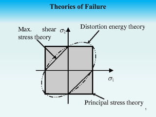
  • 8. A graph of these equation is given in the figure. Any given state of stress will be represented in this figure by a point of co-ordinate 1 and 2 where 1 and 2 are two principal stresses. If these point falls within the area shown, the member is safe and if outside then member fails as a result of yielding of material. The Hexagon associated with the initiation of yield in the member is known as “Tresca Hexagon”. (1814-1885). In the first and third quadrant 1 and 2 have the same signs and 8
  • 9. max is half of the numerically larger value of principal stress 1 or 2. In the second and fourth quad, where 1 and 2 are of opposite sign, max is half of arithmetical sum of the two 1 and 2. In fourth quadrant, the equation of the boundary or limit (yield/boundary stress) stress line is 1 - 2 = y And in the second quadrant the relation is 1 - 2 = -y 9
  • 10. y       2 1 y     1 y    1 y    2 y      2 1 y     2 10
  • 11. Problem 01 The solid circular shaft in Fig. (a) is subject to belt pulls at each end and is simply supported at the two bearings. The material has a yield point of 36,000 Ib/in2• Determine the required diameter of the shaft using the maximum shear stress theory together with a safety factor of 3. 11
  • 12. 400 + 200 lb 200 + 500 lb 12
  • 17. Problem 02 The state of plane stress shown occurs at a critical point of a steel machine component. As a result of several tensile tests, it has been found that the tensile yield strength is y = 250 MPa for the grade of steel used. Determine the factor of safety with respect to yield, using (a) the maximum-shearing-stress criterion, and (b) the maximum-distortion- energy criterion. 17
  • 18. 18
  • 19. SOLUTION Mohr's Circle. We construct Mohr's circle for the given state of stress and find MPa OC y x ave 20 ) 40 80 ( ) ( 2 1 2 1          MPa FX CF R m 65 ) 25 ( ) 60 ( ) ( ) ( 2 2 2 2        Principal Stresses MPa CA OC a 85 65 20        MPa CA OC b 45 65 20        a. Maximum-Shearing-Stress Criterion. Since for the grade of steel used the tensile strength is ay = 250 MPa, the corresponding shearing stress at yield is MPa MPa Y Y 125 ) 250 ( 2 1 2 1      19
  • 20. MPa For m 65    2 . 19 . 65 125 .    S F MPa MPa S F m Y   20
  • 21. b. Maximum-Distortion-Energy Criterion. Introducing a factor of safety into Eq. (7.26), we write 2 2 2 .          S F Y b b a a      For a = +85 MPa, b = -45 MPa, and y = 250 MPa, we have        2 2 2 . 250 45 45 85 85           S F  19 . 2 . . 250 3 . 114   S F S F 21
  • 22. Comment. For a ductile material with y = 250 MPa, we have drawn the hexagon associated with the maximum-shearing-stress criterion and the ellipse associated with the maximum-distortion-energy criterion. The given state of plane stress is represented by point H of coordinates a = 85 MPa and b = -45 MPa. We note that the straight line drawn through points O and H intersects the hexagon at point T and the ellipse at point M. For each criterion, the value obtained for F.S. can be verified by measuring the line segments indicated and computing their ratios:     19 . 2 . 2 . 19 .     OH OM S F b OH OT S F a 22
  • 23. 23
  • 24. The solid shaft shown in Fig. 10-41a has a radius of 0.5 in. and is made of steel having a yield stress of y = 36 ksi. Determine if the loadings cause the shaft to fail according to the maximum-shear-stress theory and the maximum-distortion-energy theory. Example 10-12 Solution The state of stress in the shaft is caused by both the axial force and the torque. Since maximum shear stress caused by the torque occurs in the material at the outer surface, we have 24
  • 25. ksi in in in kip J Tc ksi in kip A P xy x 55 . 16 2 / .) 5 . 0 ( .) 5 . 0 .( . 25 . 3 10 . 19 .) 5 . 0 ( 15 4 2           The stress components are shown acting on an element of material at point A in Fig. 10-41b. Rather than using Mohr's circle, the principal stresses can also be obtained using the stress-transformation equations, Eq.9-5. 2 2 2 , 1 2 2 2 , 1 ) 55 . 16 ( 2 0 10 . 19 2 0 10 . 19 2 2                                  xy y x y x 25
  • 26. = -9.55 ± 19.11 CTI = 9.56 ksi CT2 = -28.66 ksi Maximum-Shear-Stress Theory. Since the principal stresses have opposite signs, then from Sec. 9.5, the absolute maximum shear stress will occur in the plane, and therefore, applying the second of Eq. 10-27, we have   36 2 . 38 36 66 . 28 56 . 9 ? 2 1       Y    26
  • 27. Thus, shear failure of the material will occur according to this theory. Maximum-Distortion-Energy Theory. Applying Eq. 10-30, we have Using this theory, failure will not occur.          1296 1187 ) 36 ( 66 . 28 66 . 28 56 . 9 56 . 9 ) ( 2 ? 2 2 2 2 2 1 2 1          y      27
  • 28. Maximum Principal Stress theory or (Rankine Theory) According to this theory, it is assumed that when a member is subjected to any state of stress, fails (fracture of brittle material or yielding of ductile material) when the principal stress of largest magnitude. (1) in the member reaches to a limiting value that is equal to the ultimate normal stress, the material can sustain when subjected to simple tension or compression. The equations are shown graphically as ) 1 ( 1 ult    ) 2 ( 2 ult    28
  • 29. ult   These equations are shown graphically if the point obtained by plotting the values of 1 + 2 falls within the square area the member is safe. 29
  • 30. It can be seen that stress co-ordinate 1 and 2 at a point in the material falls on the boundary for outside the shaded area, the material is said to be fractured failed. Experimentally, it has been found to be in close agreement with the behavior of brittle material that have stress-strain diagram similar in both tension and compression. It cab be further noticed that in first and third quad, the boundary is the save as for maximum shear stress theory. Problem A thin-walled cylindrical pressure vessel is subject to an internal pressure of 600 lb/in2. the mean radius of the cylinder is 15in. If the material ha a yield point of 39,000lb/in2 and a safety of 3 is employed, 30
  • 31. determine the required wall thickness using (a) the maximum normal stress theory, and (b) the Huber-von Mises-Hencky theory. P = 600psi. r = 15" y = 39000psi F.O.S = 3 t = ? According to  c  Circumferential stress / girth stress where Pr t c   31
  • 32. By comparing 1 = c. Thus, According to the normal stress theory, maximum Principal stress should be equal to yield stress/FOS i.e. |1| ≤ ult |2| ≤ ult f = maximum (|1|, |2|, |3| - ult = 0) t t t stress al lengitudin For t t c l c 4500 2 " 15 600 2 Pr 9000 " 15 600           32
  • 33. As y = 39000psi . 69 . 0 9000 13000 9000 3 39000 Ans t t t     Problem 02:- The solid circular shaft in Fig. 18-12(a) is subject to belt pulls at each end and is simply supported at the two bearings. The material has a yield point of 36,000 Ib/in2• Determine the required diameter of the shaft using the maximum normal stress theory together with a safety factor of 3. 33
  • 34. 400 + 200 lb 200 + 500 lb 34
  • 35. 35
  • 38.    2 2 2 2 2 1 2 2 2 2 xy y x y x xy y x y x                                       2 3 2 3 3 1 20 . 24446 2 42800 2 42800                d d d  According to maximum normal stress theory . 2 3 2 3 3 1 20 . 24446 2 42800 2 42800 3 36000                 d d d ult   38
  • 40. Mohr’s Criterion:- In some material such as cast iron, have much greater strength in compression than tension so Mohr proposed that is 1st and third quadrant of a failure brokes, a maximum principal stress theory was appropriate based on the ultimate strength of materials in tension or compression. Therefore in 2nd and 4th quad, where the maximum shear stress theory should apply. Pure shear is one in which x and y are equal but of opposite sense. 40
  • 41.  c ult  Failure or strength envelope Pure shear Smaller tension strength Largest compressive strength 41
  • 43. Problem 3:- In a cast-iron component the maximum principal stress is to be limited to one-third of the tensile strength . Determine the maximum value of the minimum principal stresses ,using the Mohr theory. What would be the values of the principal stresses "associated with a maximum shear stress of 390 MN/m2? The tensile and compressive strengths of the cast iron are 360 MN/m2 and 1.41 GN/m2 respectively 43
  • 45. By using principal stress theory 2 2 2 1 / 414 / 360 ) ( ) ( m MN m MN As b a c ult t ult ult ult               2 1 / 120 m MN    Maximum principal stress = 360/3 = 120 MN/m2 (tension). According to Mohr's theory, in the second and fourth quadrant From (a) and (b) 45
  • 46. Therefore 2 2 2 / 940 1 1410 360 120 m MN and        The Mohr's stress circle construction for the second part of this problem is shown in Fig. 13.7. If the maximum shear stress is 390 MN/m2, a circle is drawn of radius 390 units to touch the two envelope lines. The principal stresses can then be read off as +200 MN/m2 and -580 MN/m2• 1 1 1 2 1 2 1     c ult t ult c ult t ult and         46
  • 49. Now from second state 2 1 2 1 max 2 1 2 1 2 1 c ult 2 1 t ult 2 max 2 2 1414 380 quad fourth in and theory stress shearing By / 390                               R Also Thus m MN 49
  • 50. Example 10-11 The solid cast-iron shaft shown in Fig. 10-40a is subjected to a torque of T = 400 Ib . ft. Determine its smallest radius so that it does not fail according to the maximum-normal-stress theory. A specimen of cast iron, tested in tension, has an ultimate stress of (σult)t = 20 ksi. Solution The maximum or critical stress occurs at a point located on the surface of the shaft. Assuming the shaft to have a radius r, the shear stress is 3 4 max . . 8 . 055 ) 2 / ( ) / . 12 )( . 400 ( r in lb r r ft in ft lb J Tc       50
  • 51. 51
  • 52. 52
  • 53. Mohr's circle for this state of stress (pure shear) is shown in Fig. 10- 40b. Since R = max, then The maximum-normal-stress theory, Eq. 10-31, requires |1| ≤ ult 3 max 2 1 . . 8 . 3055 r in lb        2 3 / 000 , 20 . . 8 . 3055 in lb r in lb  Thus, the smallest radius of the shaft is determined from . . 535 . 0 / 000 , 20 . . 8 . 3055 2 3 Ans in r in lb r in lb   53
  • 54. The solid shaft shown in Fig. 10-41a has a radius of 0.5 in. and is made of steel having a yield stress of y = 36 ksi. Determine if the loadings cause the shaft to fail according to the maximum-shear-stress theory and the maximum-distortion-energy theory. Example 10-12 Solution The state of stress in the shaft is caused by both the axial force and the torque. Since maximum shear stress caused by the torque occurs in the material at the outer surface, we have 54
  • 55. ksi in in in kip J Tc ksi in kip A P xy x 55 . 16 2 / .) 5 . 0 ( .) 5 . 0 .( . 25 . 3 10 . 19 .) 5 . 0 ( 15 4 2           The stress components are shown acting on an element of material at point A in Fig. 10-41b. Rather than using Mohr's circle, the principal stresses can also be obtained using the stress-transformation equations, Eq.9-5. 2 2 2 , 1 2 2 2 , 1 ) 55 . 16 ( 2 0 10 . 19 2 0 10 . 19 2 2                                  xy y x y x 55
  • 56. = -9.55 ± 19.11 CTI = 9.56 ksi CT2 = -28.66 ksi Maximum-Shear-Stress Theory. Since the principal stresses have opposite signs, then from Sec. 9.5, the absolute maximum shear stress will occur in the plane, and therefore, applying the second of Eq. 10-27, we have   36 2 . 38 36 66 . 28 56 . 9 ? 2 1       Y    56
  • 57. Thus, shear failure of the material will occur according to this theory. Maximum-Distortion-Energy Theory. Applying Eq. 10-30, we have Using this theory, failure will not occur.          1296 1187 ) 36 ( 66 . 28 66 . 28 56 . 9 56 . 9 ) ( 2 ? 2 2 2 2 2 1 2 1          y      57
  • 58. Maximum Normal Strain or Saint Venant’s Criterion In this theory, it is assumed that a member subjected to any state of stress fails (yields) when the maximum normal strain at any point equals, the yield point strain obtained from a simple tension or compression test (y = σy/). Principal strain of largest magnitude |max| could be one of two principal strain 1 and 2 depending upon the stress conditions acting in the member . Thus the maximum Principal strain theory may be represented by the following equation. 58
  • 59. ) 1 ( 2 max 1 max           y y       As stress in one direction produces the lateral deformation in the other two perpendicular directions and using law of superposition, we find three principal strains of the element. x= y= z= σx σx / E -μσx / E -μσx / E σy μσy / E σy / E -μσy / E σz –μσz / E -μσz / E σz / E x= y= z= x= y= z= 59
  • 60. x = σx / E -μσy / E -μσz / E = σx / E -μ / E (σy + σz) y = σy / E -μσx / E -μσz / E = σy / E -μ / E (σx + σz) z = σz / E -μσy / E -μσx / E = σz / E -μ / E (σx + σy) (2) Thus ) 3 ( ) ( ) ( ) ( 1 2 3 3 3 1 2 2 3 2 1 1                                     E E E E E E 60
  • 62. The yield surface ABCD is the straight under biaxial tension or biaxial compression Individual principal stresses greater than σy can occur without causing yielding. 62
  • 63. Maximum Shear Strain Energy (Distortion Energy Criterion (Von MISES Criterion) According to this theory when a member is subjected to any state of stress fails (yields) when the distortion energy per unit volume at a point becomes equal to the strain energy of distortion per unit volume at failure (yielding) in uniaxial tension (or compression). The distortion strain energy is that energy associated with a change in the shape of the body. The total strain energy per unit volume also called strain energy density is the energy in a body stored internally throughout its volume due to deformation produced by external loading. If the axial stress 63
  • 64. arising in a tension test is “” and the corresponding axial strain is ε then the work done or a unit volume of the test specimen is the product of mean value of the force per unit area (/2) times the displacement in the direction of the force, or ε. The work is thus ) 1 ( 2   U This work is stored as internal strain energy. When an elastic element subjected to triaxial loading as show in Fig the stresses can be resolves in to three principal stresses σ1,σ2 and σ3. where 1,2 and 3 are the principal axes. These three principal stresses will be accompanied by these principal strain related to the stresses by equations 3,4and 5 64
  • 65. If it is assumed that loads are applied gradually and simultaneous then stresses and strain will increase in the same manner. The total strain energy per unit volume in the sum of energies produced by each of the stresses (as energy is a scalar quantity ) E u E ) ( 3 2 1 1        E u E ) ( 3 1 2 2        E u E ) ( 2 1 3 3        (2) (3) (4) 65
  • 66. Where ε1, ε2, and ε3, are the normal strain in the direction of principal stresses respectively of strain are expressed in term of stresses than equation (5) taken the following form ) 5 ( , 2 1 , , 2 1 , , 2 1 3 3 2 2          U                                              E E E E E E E E E U 2 1 3 3 3 1 2 2 3 2 1 1 2 1 2 1 ) ( 2 1                Which can be reduced to   ) 6 ( ) ( 2 2 1 3 2 3 1 2 1 3 3 2 2 2 1                 E U 66
  • 67. As the deformation of a material can be separated in to two parts  (a) Change in volume, (b) change in shape or distortion. Similarly the total strain energy can be broken in to two parts. One part representing the energy needed to cause volume change of the element with no change in shape (Uv) and the other part representing the energy needed to distort the element (Ud). ) 7 ( d v U U U   67
  • 68. 1 3 1 (a)    (b) 1-  3-  2-  (c) 68 The principal stresses σ1,σ2 and σ3 of Fig. (01) can be resolved in to two states of stresses in Fig. (02) b & c. the state of stress shown in Fig. b represents a hydrostatic stress condition in which all these principal stress are equal to the quantity σ.
  • 69. Some materials were subjected to hydrostatic pressure resulting in appreciable changes in volume but no change in shape and no failure by yielding. Therefore the remaining portion of the stress (1 - ), (2 - ) and (3 - ) will result in distortion only (No volume change) and the algebraic sum of the three principal strains produced by the three principal stresses (1 - ave), (2 - ave) and (3 - ave) must be equal to zero. i.e (ε1+ε2+ε3)d=0 (9) Expressing strains in term of stresses. 69
  • 70.                           0 2 1 3 1 3 2 3 2 1 3 2 1                                              d E                                     2 2 2 2 1 3 1 3 2 3 2 1                               2 2 2 2 1 3 1 3 2 3 2 1                           6 3 3 3 3 2 2 2 1 1 1                    6 3 2 2 2 3 3 2 2 1 1         70
  • 71. a) One part that causes Volumetric (Uv) b) Change and one causes distortion an (Ud) ) 4 ( d v U U U   a) As according to theory of distortion only energy due to distortion is responsible for failure. Some experimental evidence supports this assumption some materials were subjected to hydrostatic pressure result in appreciable changes in volume but no change in shape and no failure by yielding. The hydrostatic pressure is the average of three principal stresses 1 2 and 3 known as average stress. ) 5 ( 3 3 2 1 max        71
  • 72. This principal strains ε in the material. Due to there Principal stresses (1, 2, 3) three principal strains ε1, ε2, and ε3, are produced. The state of stress in Fig below will result in distortion only (No volume change) if sum of three normal strains is zero. That is             ) 6 ( 0 2 2 2 1 ) ( 2 1 3 3 1 2 3 2 2 1 3 2 1                                             u E E Which eh reduces to   ) 5 ( 3 / 0 3 ) 2 1 ( 3 2 1 3 2 1                  72
  • 73. The normal strains corresponding to these stresses are found from three dimension from of Hook’s law given by the following equation. ) 7 ( ) 2 1 ( E      Strain energy resulting from these stresses or strains can be obtained by subject through these values is ) 8 ( . 2 3 . 2 1 . 2 1 . 2 1 , 3 2 1 3 2 1                           Uv 73
  • 74. (5) 3 ) ( ) 2 1 ( 3 ) ( . 2 3 3 2 1 3 2 1             E u Uv 2 3 2 1 ) ( 6 ) 2 1 (        E u Uv (9) Strain energy due to distortion U=Uy + Ud Ud = U- Uy                             2 3 2 1 3 2 3 1 2 1 2 3 2 2 2 1 6 2 1 2 2 1             E u u E Ud (10)      2 3 2 1 3 2 3 1 2 1 2 3 2 2 2 1 2 1 ) ( 6 ) ( 3 6 1                       u u E Ud 74
  • 75. When the third force in the         2 1 1 3 2 3 2 3 3 2 2 2 2 2 2 1 2 1 2 2 2 6 1                       E u Ud         2 1 3 2 3 2 2 2 1 6 1              E u Ud (12) (13) For biaxial stress system, σ3 = 0   2 2 2 1 2 1 2 3 1         E u Ud (14) For uniaxial stress system   2 1 3 1  E u Ud   (15) 75
  • 76. For Distortion theory the failure occurs when distortion energy of the member however equal to the strain energy of distortion at failure (yielding) in uniaxial torsion (or equilibrium). So substituting σ1=σy in equ (15)   2 2 6 1 y d E u U    (16) And equating it with (13)         2 1 3 2 3 2 2 2 1 2 6 1 ) 2 ( 6 1                E u E u y      2 1 3 2 3 2 2 2 1 2 2              y (17) 76
  • 77. For biaxial stress system 2 2 2 1 2 1 2 2         y (18) 77