Downloaded 275 times

![D-21
Design Examples V14.0
AMERICAN INSTITUTE OF STEEL CONSTRUCTION
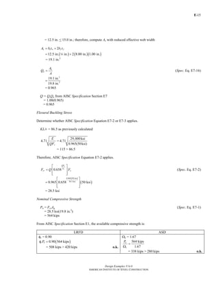
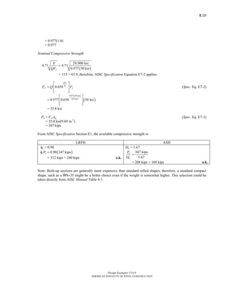
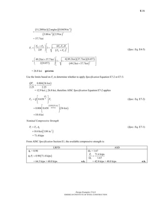
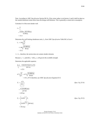
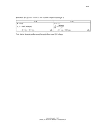
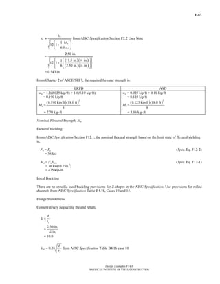
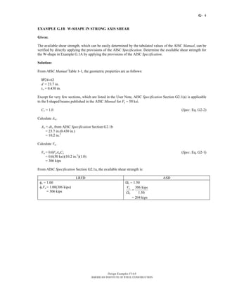
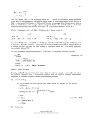
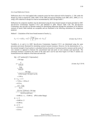
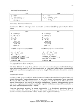
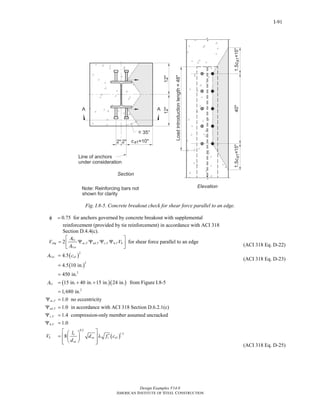
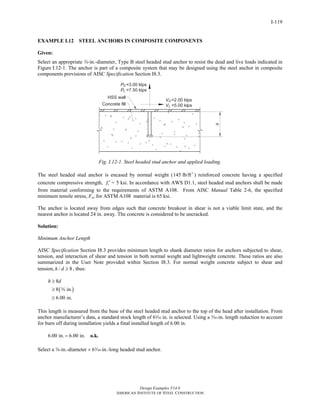
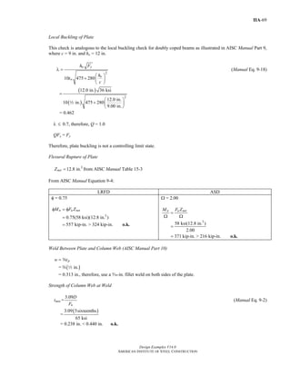
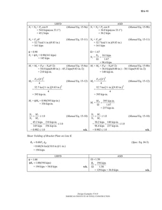
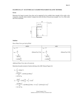
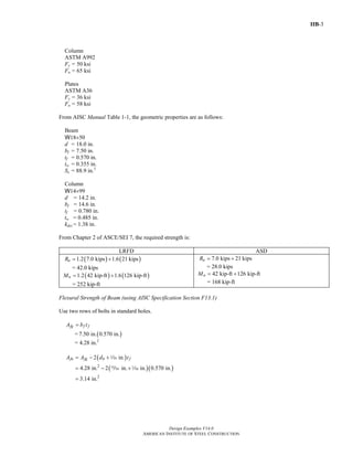
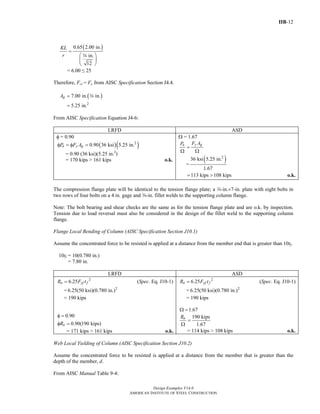
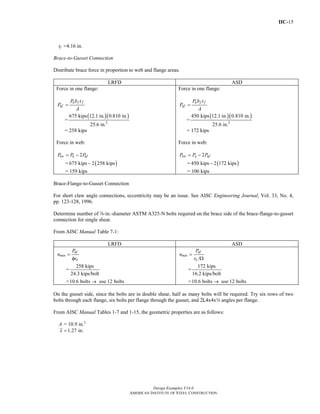
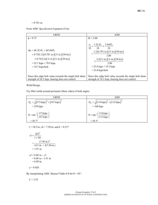
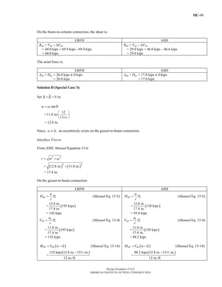
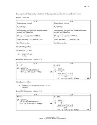
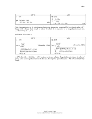
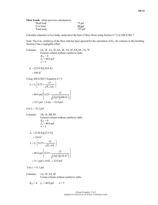
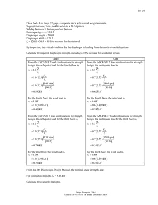
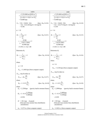
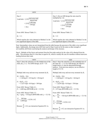
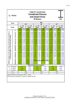
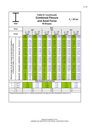
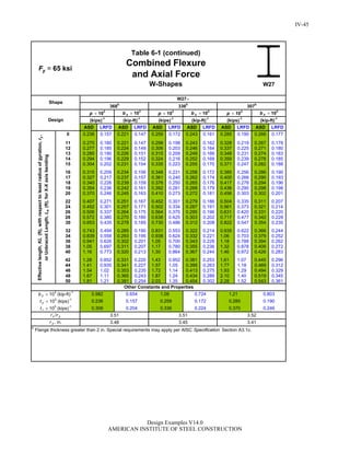
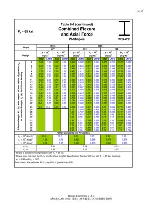
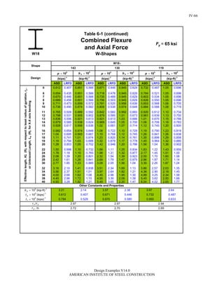
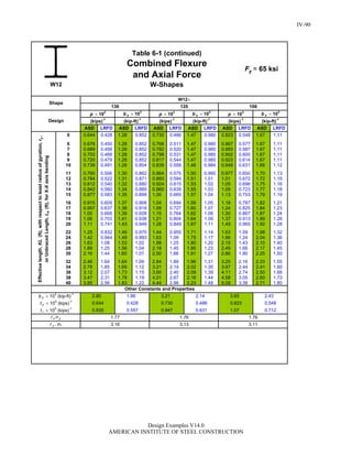
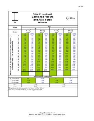
3. w > 2be + d
4.25 in. > 2(1.61 in.) + 1.00 in.
= 4.22 in. o.k.
4. c > a
2.50 in. > 2.25 in. o.k.
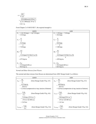
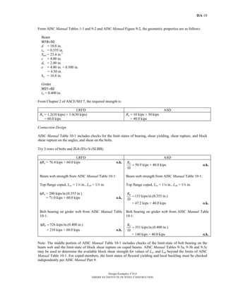
From Chapter 2 of ASCE/SEI 7, the required tensile strength is:
LRFD ASD
Pu = 1.2(4 kips) + 1.6(12 kips)
= 24.0 kips
Pa = 4 kips + 12 kips
= 16.0 kips
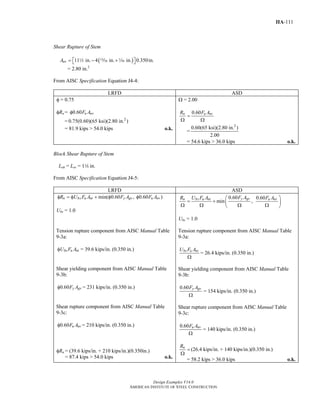
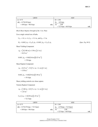
Tensile Rupture
Calculate the available tensile rupture strength on the effective net area.
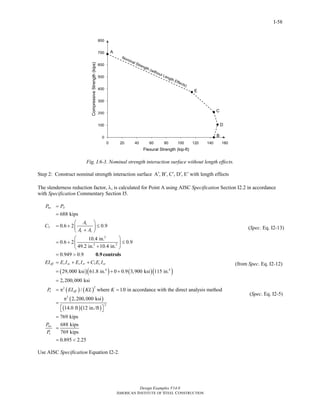
Pn = Fu(2tbe) (Spec. Eq. D5-1)
= 58 ksi (2)(0.500 in.)(1.61 in.)
= 93.4 kips
From AISC Specification Section D5.1, the available tensile rupture strength is:
LRFD ASD
φt = 0.75
φtPn = 0.75(93.4 kips)
= 70.1 kips
Ωt = 2.00
93.4 kips
2.00
n
t
P
=
Ω
= 46.7 kips
Shear Rupture
Asf = 2t(a + d/2)
= 2(0.500 in.)[2.25 in. + (1.00 in./2)]
= 2.75 in.2
Pn = 0.6FuAsf (Spec. Eq. D5-2)
= 0.6(58 ksi)(2.75 in.2
)
= 95.7 kips
From AISC Specification Section D5.1, the available shear rupture strength is:
LRFD ASD
φsf = 0.75
φsfPn = 0.75(95.7 kips)
= 71.8 kips
Ωsf = 2.00
95.7 kips
2.00
n
sf
P
=
Ω
= 47.9 kips
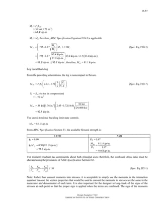
Bearing
Apb = 0.500 in.(1.00 in.)
= 0.500 in.2
Return to Table of Contents](https://image.slidesharecdn.com/steel-construction-manual-design-examples-v14-0-pdf-151204051221-lva1-app6892/85/Steel-Construction-Manual-Design-examples-48-320.jpg)
![E-
Design Examples V14.0
AMERICAN INSTITUTE OF STEEL CONSTRUCTION
13
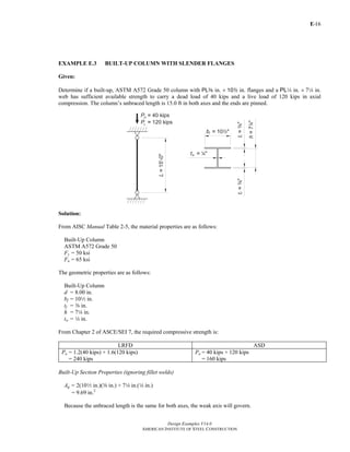
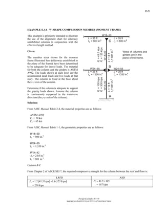
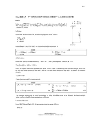
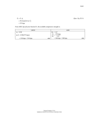
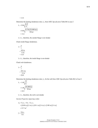
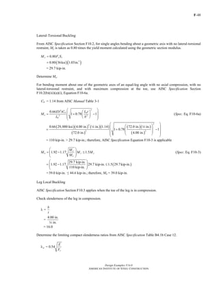
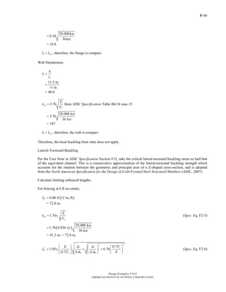
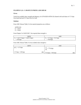
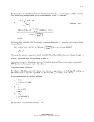
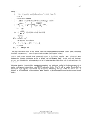
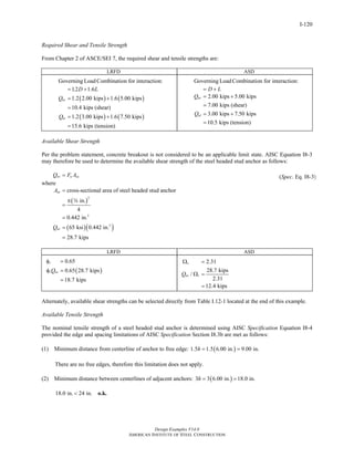
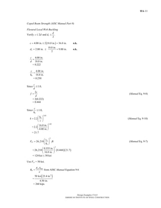
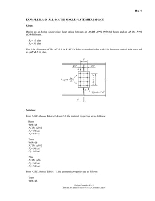
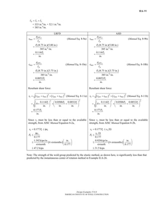
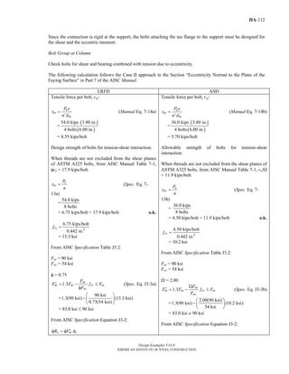
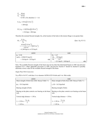
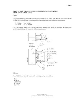
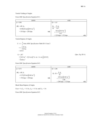
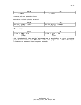
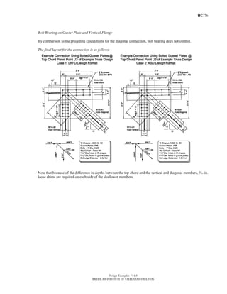
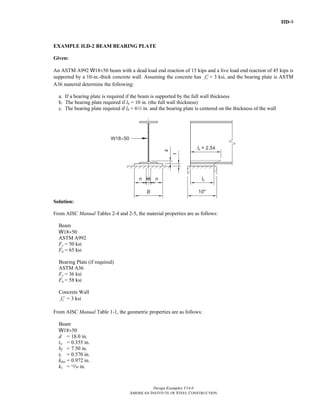
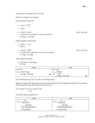
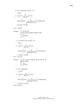
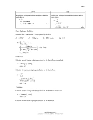
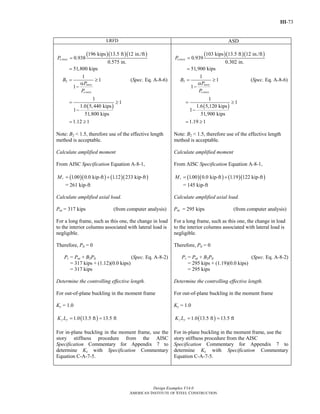
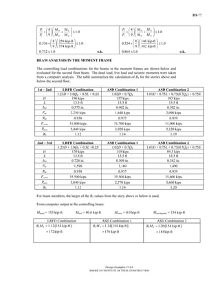
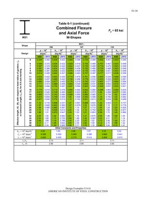
From AISC Design Guide 9, Equation 3.4,
J =
3
3
bt
∑
=
( )( ) ( )( )
3 3
2 8.00 in. 1.00 in. + 15.0 in. in.
3
4
= 5.41 in4
Fe =
( )
2
2
1
+
+
w
x yz
EC
GJ
I IK L
⎡ ⎤π
⎢ ⎥
⎢ ⎥⎣ ⎦
(Spec. Eq. E4-4)
=
( )( )
( )( )( )
( )( )
2 6
4
2 4 4
29,000ksi 5,470in. 1
+ 11,200ksi 5.41in.
1,100in. 85.4in.1.0 15ft 12
⎡ ⎤π ⎛ ⎞⎢ ⎥⎜ ⎟
+⎢ ⎥⎝ ⎠⎡ ⎤⎣ ⎦⎣ ⎦
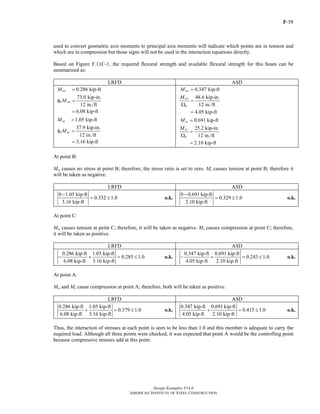
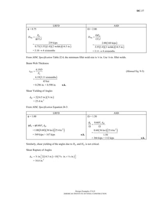
= 91.9 ksi > 38.3 ksi
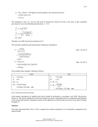
Therefore, the flexural buckling limit state controls.
Use Fe = 38.3 ksi.
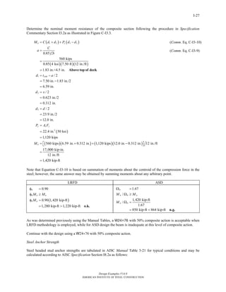
Slenderness
Check for slender flanges using AISC Specification Table B4.1a, then determine Qs, the unstiffened element
(flange) reduction factor using AISC Specification Section E7.1.
Calculate kc using AISC Specification Table B4.1b note [a].
kc =
4
wh t
=
4
15.0 in. in.4
= 0.516, which is between 0.35 and 0.76
For the flanges,
b
t
λ =
=
4.00in.
1.00in.
= 4.00
Determine the flange limiting slenderness ratio, λr, from AISC Specification Table B4.1a case 2
0.64
c
r
y
k E
F
λ =
=
( )0.516 29,000 ksi
0.64
50 ksi
= 11.1
rλ < λ ; therefore, the flange is not slender and Qs = 1.0.
Return to Table of Contents](https://image.slidesharecdn.com/steel-construction-manual-design-examples-v14-0-pdf-151204051221-lva1-app6892/85/Steel-Construction-Manual-Design-examples-66-320.jpg)
![E-
Design Examples V14.0
AMERICAN INSTITUTE OF STEEL CONSTRUCTION
17
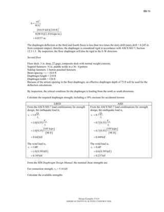
( )( ) ( )( )
3 3
in. 10 in. 7 in. in.
2
12 12
yI
⎡ ⎤
= +⎢ ⎥
⎢ ⎥⎣ ⎦
a 2 4 4
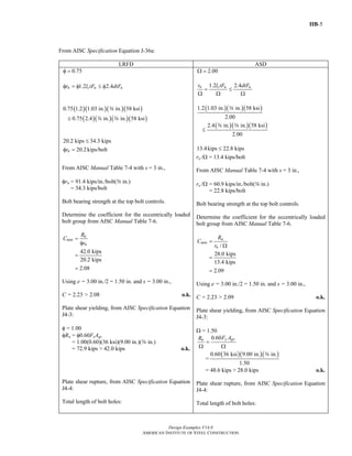
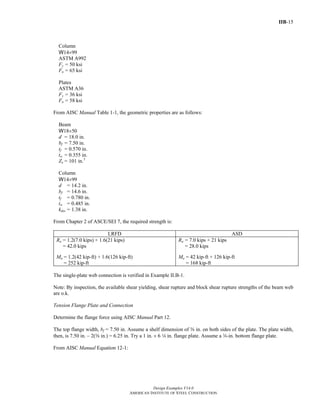
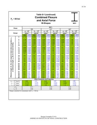
= 72.4 in.4
y
y
I
r
A
=
4
2
72.4 in.
9.69 in.
=
= 2.73 in.
Ix = ( )( )( )
( )( ) ( )( )
3 3
2 in. 7 in. 2 10 in. in.
2 10 in. in. 3.81 in. + +
12 12
4 4 2 a
2 a
= 122 in.4
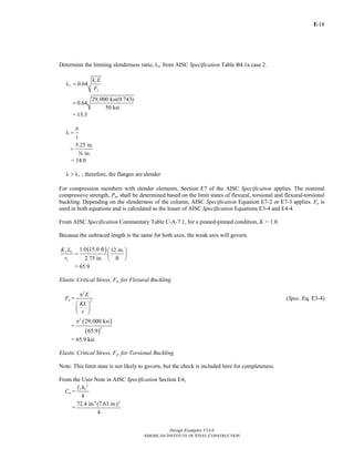
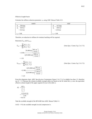
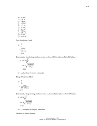
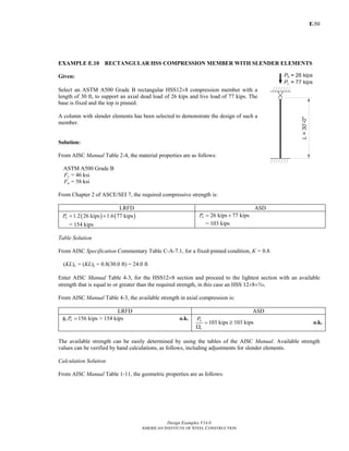
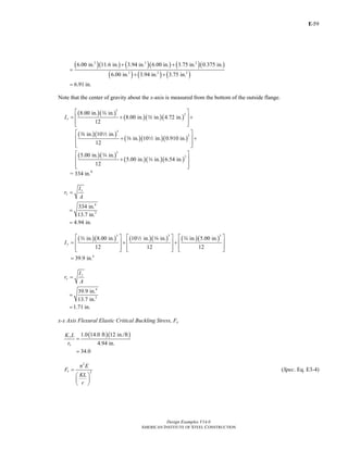
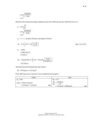
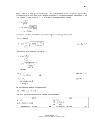
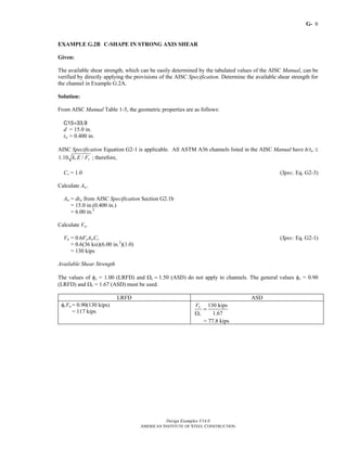
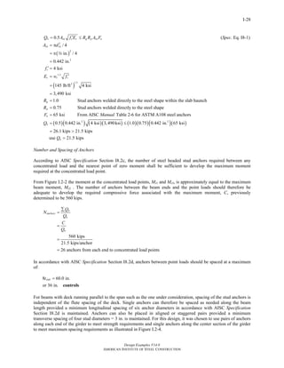
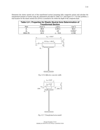
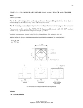
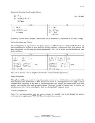
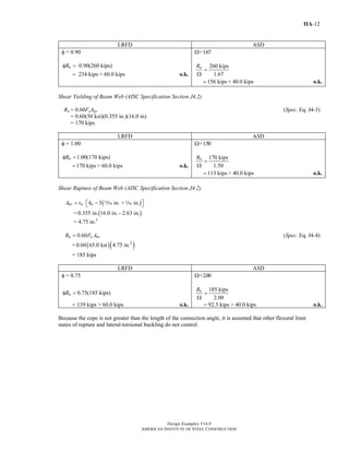
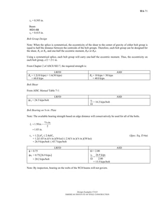
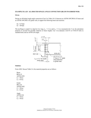
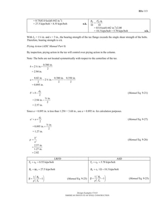
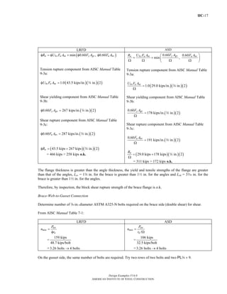
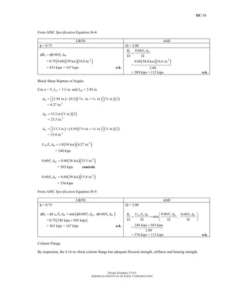
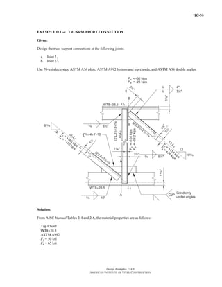
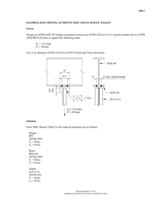
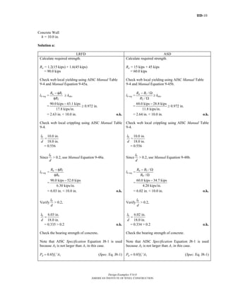
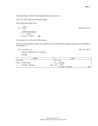
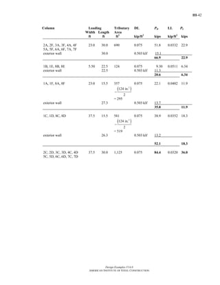
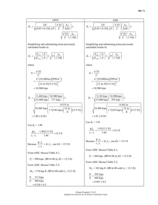
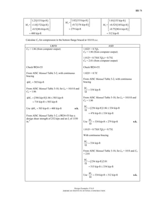
Web Slenderness
Determine the limiting slenderness ratio, λr, from AISC Specification Table B4.1a case 5:
1.49r
y
E
F
λ =
29,000 ksi
1.49
50 ksi
=
= 35.9
w
h
t
λ =
7 in.
in.
=
4
4
= 29.0
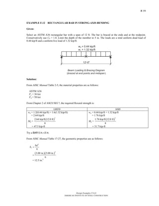
rλ < λ ; therefore, the web is not slender.
Note that the fillet welds are ignored in the calculation of h for built up sections.
Flange Slenderness
Calculate kc.
4
c
w
k
h t
= from AISC Specification Table B4.1b note [a]
4
7 in. in.
=
4 4
= 0.743, where 0.35 M kc M 0.76 o.k.
Use kc = 0.743
Return to Table of Contents](https://image.slidesharecdn.com/steel-construction-manual-design-examples-v14-0-pdf-151204051221-lva1-app6892/85/Steel-Construction-Manual-Design-examples-70-320.jpg)
![E-
Design Examples V14.0
AMERICAN INSTITUTE OF STEEL CONSTRUCTION
57
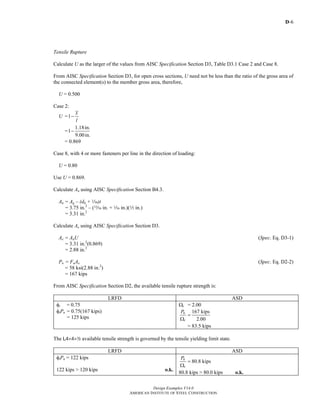
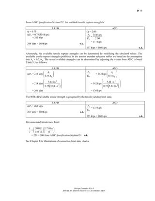
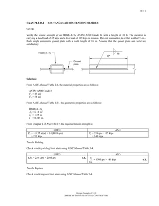
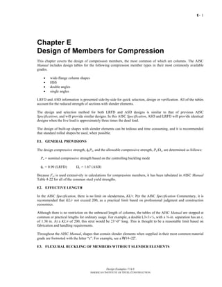
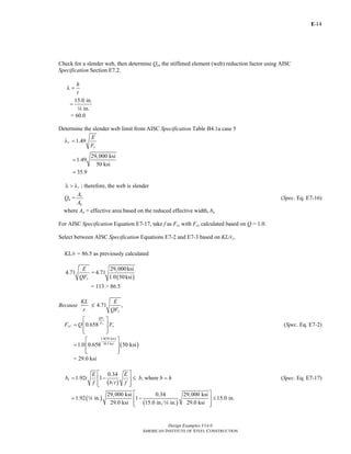
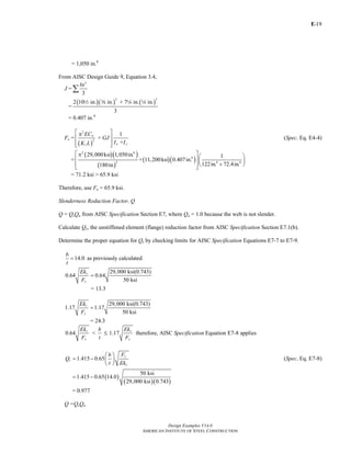
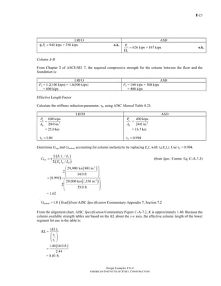
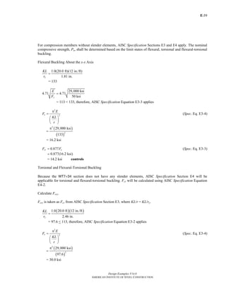
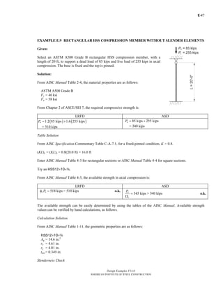
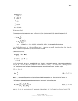
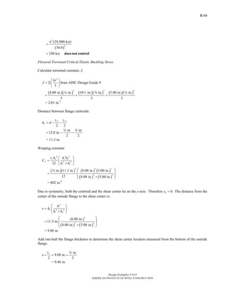
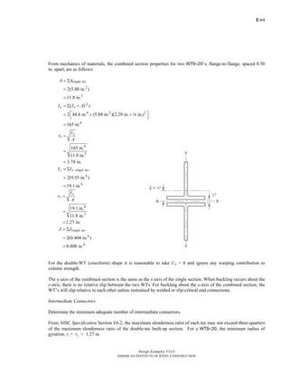
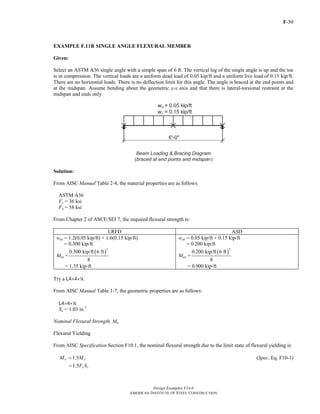
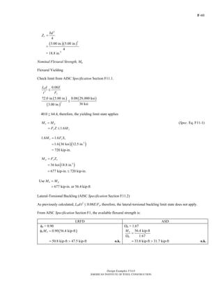
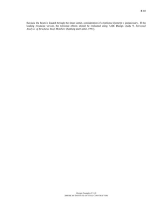
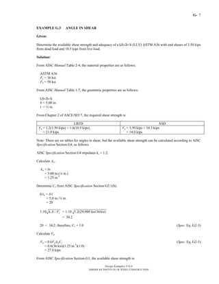
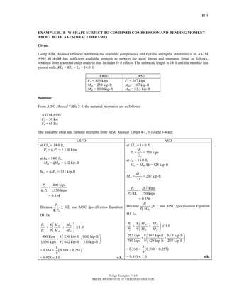
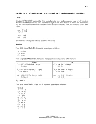
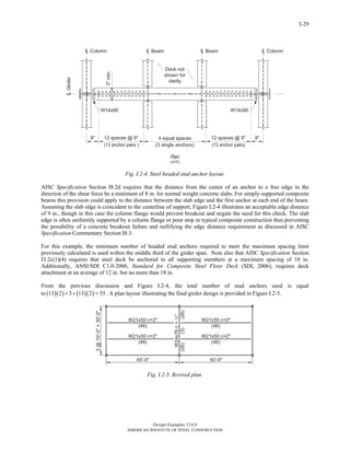
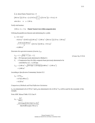
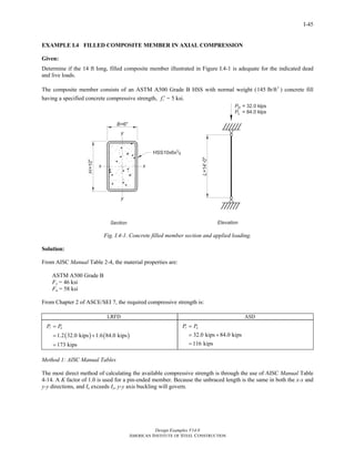
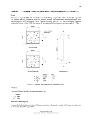
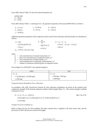
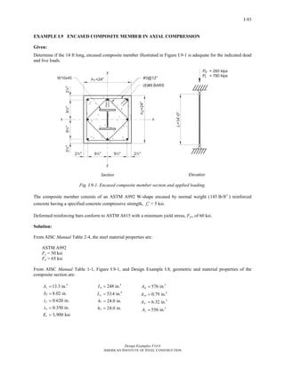
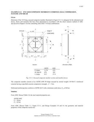
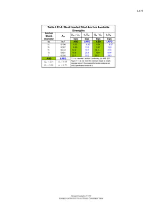
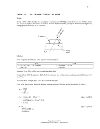
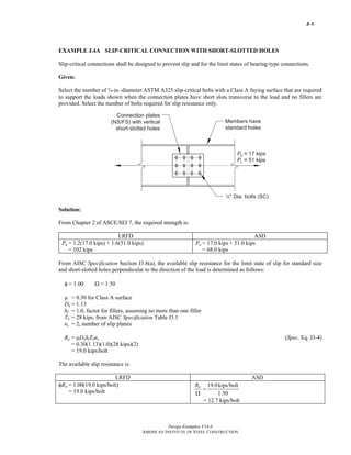
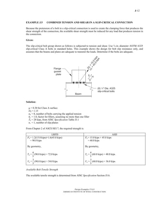
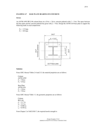
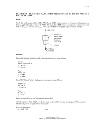
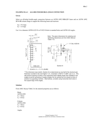
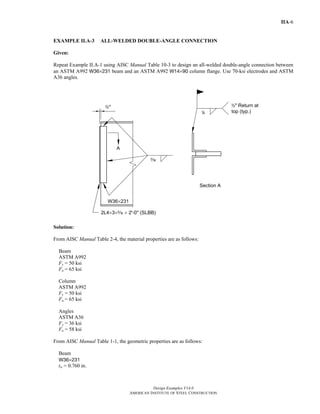
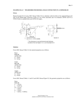
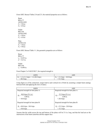
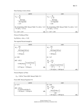
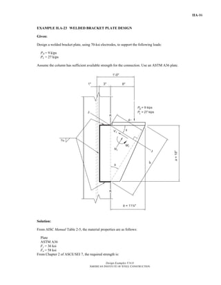
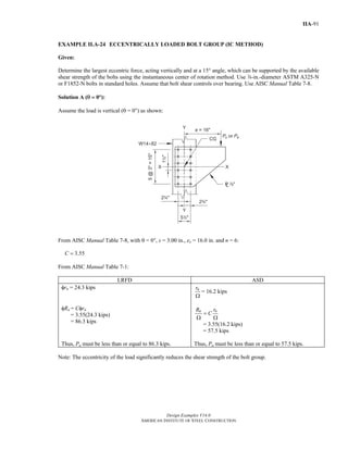
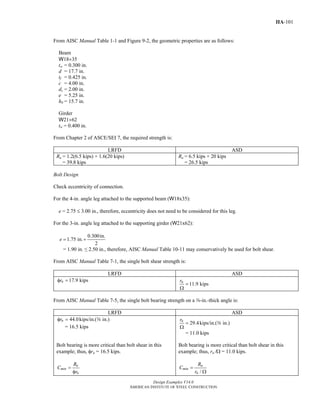
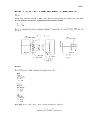
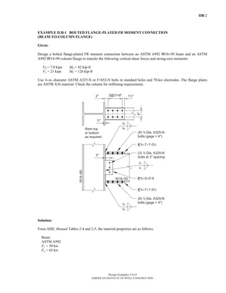
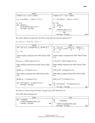
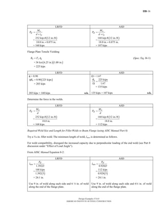
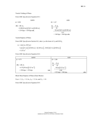
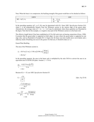
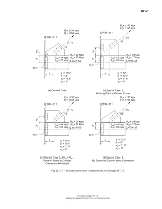
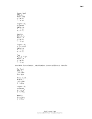
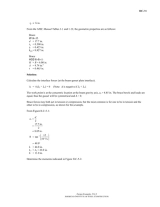
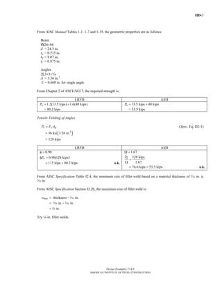
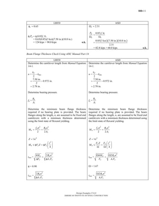
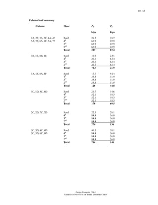
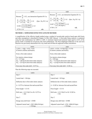
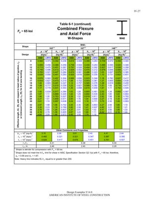
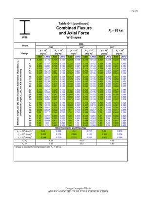
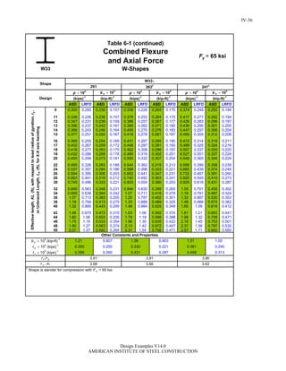
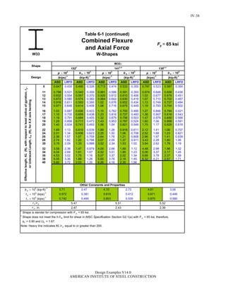
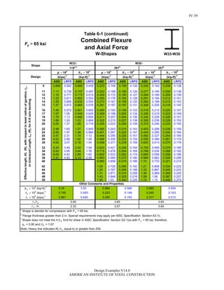
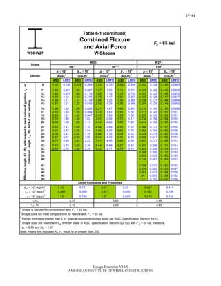
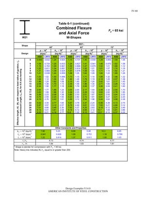
EXAMPLE E.12 BUILT-UP I-SHAPED MEMBER WITH DIFFERENT FLANGE SIZES
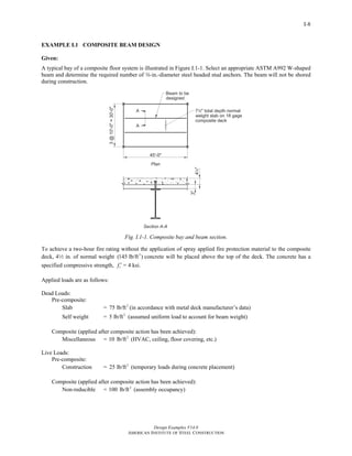
Given:
Compute the available strength of a built-up compression member with a length of 14 ft. The ends are pinned.
The outside flange is PLw-in.×5-in., the inside flange is PLw-in.×8-in., and the web is PLa-in.×102-in. Material
is ASTM A572 Grade 50.
Solution:
From AISC Manual Table 2-5, the material properties are as follows:
ASTM A572 Grade 50
Fy = 50 ksi
Fu = 65 ksi
There are no tables for special built-up shapes; therefore the available strength is calculated as follows.
Slenderness Check
Check outside flange slenderness.
Calculate kc.
4
c
w
k
h t
= from AISC Specification Table B4.1b note [a]
4
=
10 in. in.2 a
= 0.756, 0.35 0.76ck≤ ≤ o.k.
For the outside flange, the slenderness ratio is,
b
t
λ =
2.50 in.
in.
=
w
Return to Table of Contents](https://image.slidesharecdn.com/steel-construction-manual-design-examples-v14-0-pdf-151204051221-lva1-app6892/85/Steel-Construction-Manual-Design-examples-110-320.jpg)
![E-
Design Examples V14.0
AMERICAN INSTITUTE OF STEEL CONSTRUCTION
67
Thus,
( ) ( )2 2
28.9 36.6 46.6
⎛ ⎞
= + =⎜ ⎟
⎝ ⎠m
KL
r
and
2
2e
x m
E
F
KL
r
π
=
⎛ ⎞
⎜ ⎟
⎝ ⎠
(from Spec. Eq. E3-4)
2
2
(29,000 ksi)
(46.6)
132 ksi
π
=
=
Torsional buckling:
2
2
1
( )
w
e
x yz
EC
F GJ
I IK L
⎡ ⎤π
= +⎢ ⎥
+⎢ ⎥⎣ ⎦
(Spec. Eq. E4-4)
The cruciform section made up of two back-to-back WT's has virtually no warping resistance, thus the warping
contribution is ignored and Equation E4-4 becomes
4
4 4
(11,200 ksi)(0.808 in. )
(165 in. 19.1 in. )
49.2 ksi
e
x y
GJ
F
I I
=
+
=
+
=
Use the smallest elastic buckling stress, Fe, from the limit states considered above to determine Fcr by AISC
Specification Equation E7-2 or Equation E7-3, as follows:
Qs = 0.496
Fe = Fe(smallest)
= 39.6 ksi (y-axis flexural buckling)
( )0.496 50 ksi
0.626 2.25
39.6 ksi
= = <
y
e
QF
F
Therefore use Equation E7-2,
[ ]0.626
0.658
0.496 0.658 (50 ksi)
19.1 ksi
y
e
QF
F
cr yF Q F
⎡ ⎤
⎢ ⎥= ⎣ ⎦
=
=
Determine the nominal compressive strength, Pn:
Return to Table of Contents](https://image.slidesharecdn.com/steel-construction-manual-design-examples-v14-0-pdf-151204051221-lva1-app6892/85/Steel-Construction-Manual-Design-examples-120-320.jpg)
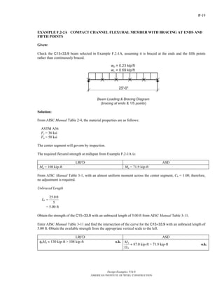
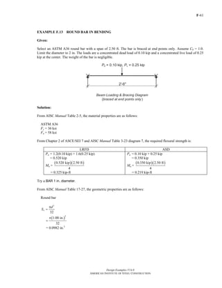
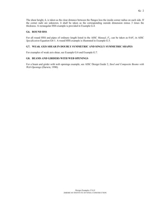
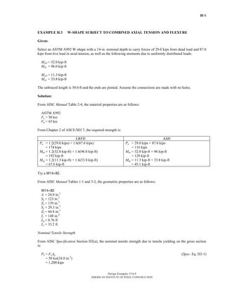
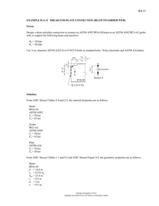
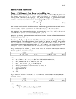
![F-3
Design Examples V14.0
AMERICAN INSTITUTE OF STEEL CONSTRUCTION
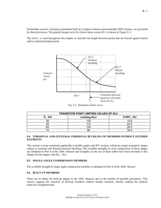
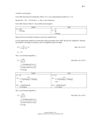
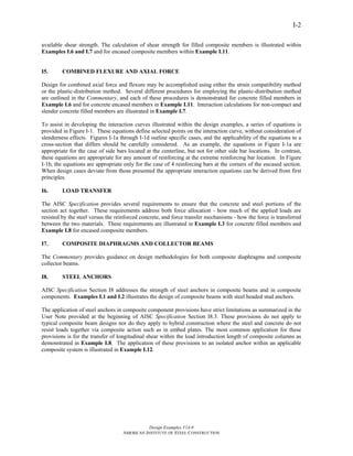
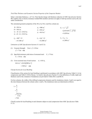
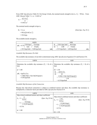
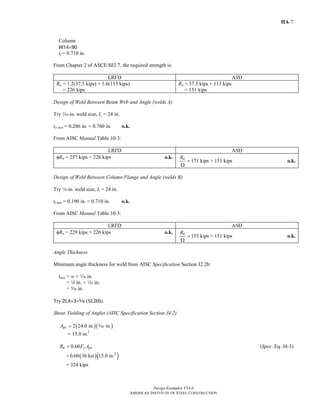
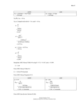
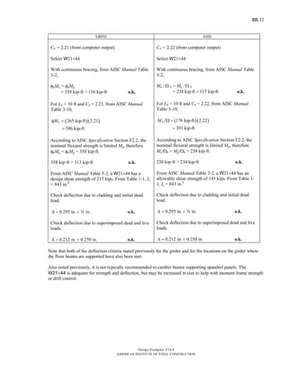
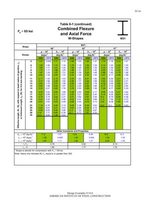
F3. DOUBLY SYMMETRIC I-SHAPED MEMBERS WITH COMPACT WEBS AND NONCOMPACT
OR SLENDER FLANGES BENT ABOUT THEIR MAJOR AXIS
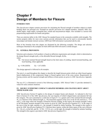
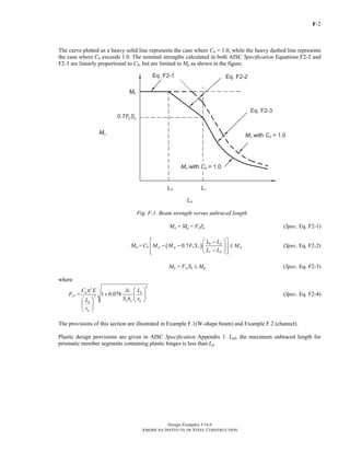
The strength of shapes designed according to this section is limited by local buckling of the compression flange.
Only a few standard wide flange shapes have noncompact flanges. For these sections, the strength reduction for Fy
= 50 ksi steel varies. The approximate percentages of Mp about the strong axis that can be developed by
noncompact members when braced such that Lb ≤ Lp are shown as follows:
W21×48 = 99% W14×99 = 99% W14×90 = 97% W12×65 = 98%
W10×12 = 99% W8×31 = 99% W8×10 = 99% W6×15 = 94%
W6×8.5 = 97%
The strength curve for the flange local buckling limit state, shown in Figure F-2, is similar in nature to that of the
lateral-torsional buckling curve. The horizontal axis parameter is λ=bf /2tf. The flat portion of the curve to the left
of λpf is the plastic yielding strength, Mp. The curved portion to the right of λrf is the strength limited by elastic
buckling of the flange. The linear transition between these two regions is the strength limited by inelastic flange
buckling.
Fig, F-2. Flange local buckling strength.
Mn = Mp = FyZx (Spec. Eq. F2-1)
Mn = ( )0.7
pf
p p y x
rf pf
M M F S
⎡ ⎤⎛ ⎞λ − λ
− −⎢ ⎥⎜ ⎟
λ − λ⎢ ⎥⎝ ⎠⎣ ⎦
(Spec. Eq. F3-1)
Mn = 2
0.9 c xEk S
λ
(Spec. Eq. F3-2)
where
kc =
4
wh t
from AISC Specification Table B4.1b footnote [a], where 0.35 ≤ kc ≤ 0.76
The strength reductions due to flange local buckling of the few standard rolled shapes with noncompact flanges
are incorporated into the design tables in Chapter 3 of the AISC Manual.
Return to Table of Contents](https://image.slidesharecdn.com/steel-construction-manual-design-examples-v14-0-pdf-151204051221-lva1-app6892/85/Steel-Construction-Manual-Design-examples-124-320.jpg)
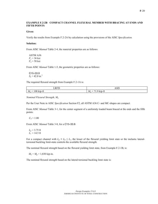
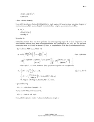

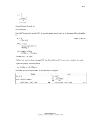
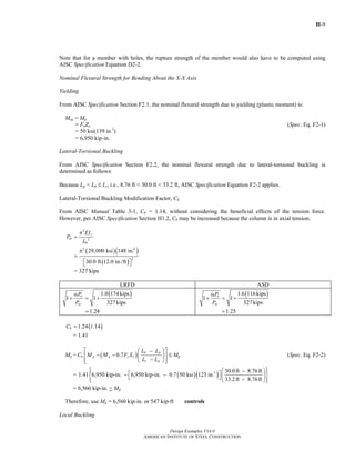
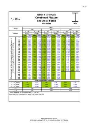
![F-53
Design Examples V14.0
AMERICAN INSTITUTE OF STEEL CONSTRUCTION
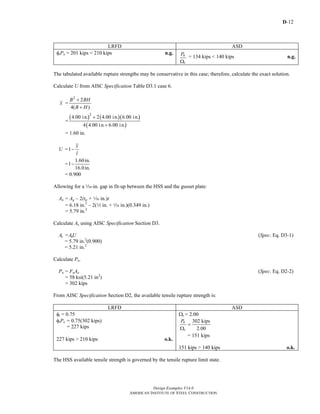
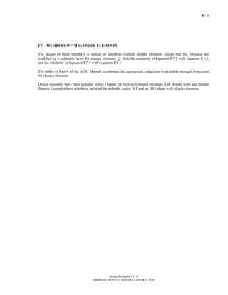
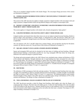
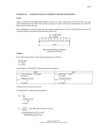
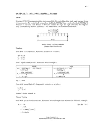
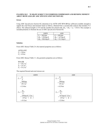
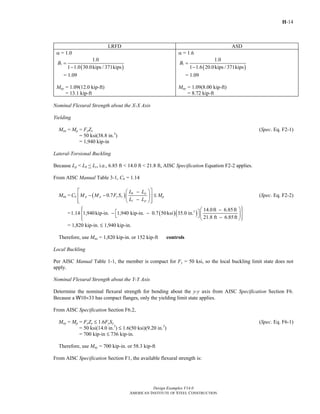
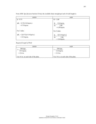
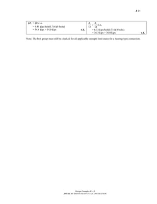
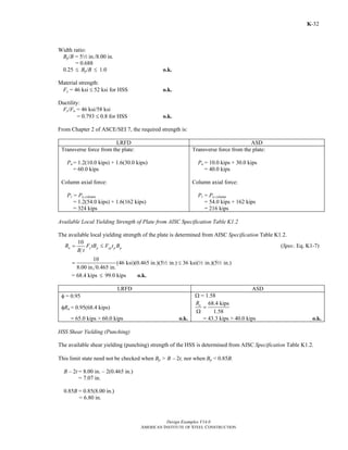
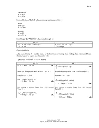
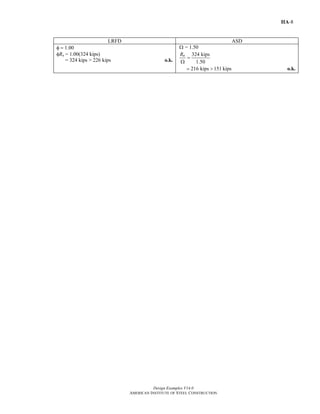
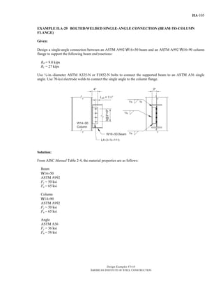
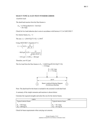
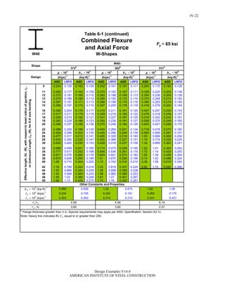
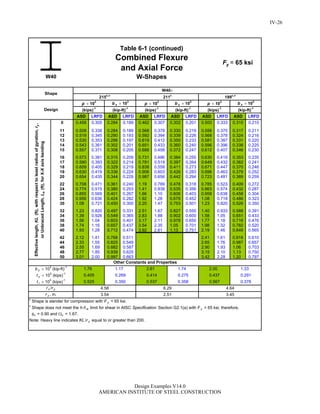
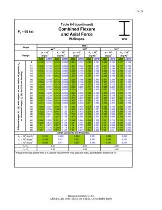
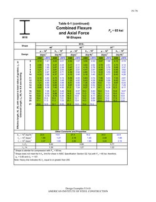
EXAMPLE F.11C SINGLE ANGLE FLEXURAL MEMBER
Given:
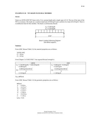
Select an ASTM A36 single angle with a simple span of 6 ft. The vertical loads are a uniform dead load of 0.05
kip/ft and a uniform live load of 0.15 kip/ft. The horizontal load is a uniform wind load of 0.12 kip/ft. There is no
deflection limit for this angle. The angle is braced at the end points only and there is no lateral-torsional restraint.
Use load combination 4 from Section 2.3.2 of ASCE/SEI 7 for LRFD and load combination 6a from Section 2.4.1
of ASCE/SEI 7 for ASD.
Solution:
From AISC Manual Table 2-4, the material properties are as follows:
ASTM A36
Fy = 36 ksi
Fu = 58 ksi
From Chapter 2 of ASCE/SEI 7, the required flexural strength is:
LRFD ASD
wux = 1.2(0.05 kip/ft) + 0.15 kip/ft
= 0.210 kip/ft
wuy = 1.0(0.12 kip/ft)
= 0.12 kip/ft
Mux =
( )
2
0.210 kip/ft 6 ft
8
= 0.945 kip-ft
Muy =
( )
2
0.12 kip/ft 6 ft
8
= 0.540 kip-ft
wax = 0.05 kip/ft + 0.75(0.15 kip/ft)
= 0.163 kip/ft
way = 0.75[(0.6)(0.12 kip/ft)]
= 0.054 kip/ft
Max =
( )
2
0.163 kip/ft 6 ft
8
= 0.734 kip-ft
May =
( )
2
0.054 kip/ft 6 ft
8
= 0.243 kip-ft
Try a L4×4×4.
Return to Table of Contents](https://image.slidesharecdn.com/steel-construction-manual-design-examples-v14-0-pdf-151204051221-lva1-app6892/85/Steel-Construction-Manual-Design-examples-174-320.jpg)


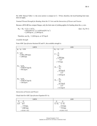
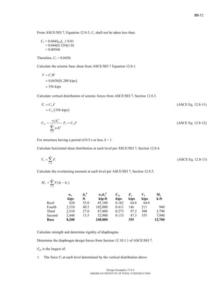
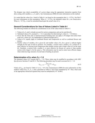
= 154 kips
Ra = wl/2
= (0.920 klf + 2.74 klf)(56.0 ft/2)
= 102 kips
Stiffener Requirement Check
Aw = dtw from AISC Specification Section G2.1(b)
= 36.0 in.(c in.)
= 11.3 in.2
Return to Table of Contents](https://image.slidesharecdn.com/steel-construction-manual-design-examples-v14-0-pdf-151204051221-lva1-app6892/85/Steel-Construction-Manual-Design-examples-207-320.jpg)
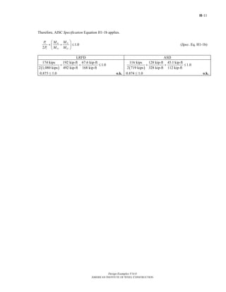
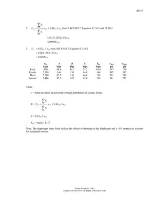
![G-
Design Examples V14.0
AMERICAN INSTITUTE OF STEEL CONSTRUCTION
18
33.0 in.
in.w
h
t
=
c
= 106
106 < 260; therefore kv = 5 for webs without transverse stiffeners from AISC Specification Section G2.1(b)
1.37 /vk E Fy = 1.37 ( )5 29,000 ksi / 36 ksi
= 86.9
106 > 86.9; therefore, use AISC Specification Equation G2-5 to calculate Cv
Cv = 2
1.51
( / )
v
w y
k E
h t F
(Spec. Eq. G2-5)
= 2
1.51(5)(29,000 ksi)
(106) (36 ksi)
= 0.541
Calculate Vn.
Vn = 0.6FyAwCv (Spec. Eq. G2-1)
= 0.6(36 ksi)(11.3 in.2
)(0.541)
= 132 kips
From AISC Specification Section G1, the available shear strength without stiffeners is:
LRFD ASD
φv = 0.90
φvVn = 0.90(132 kips)
= 119 kips
119 kips < 154 kips n.g.
Therefore, stiffeners are required.
Ωv = 1.67
132 kips
1.67
n
v
V
=
Ω
= 79.0 kips
79.0 kips < 102 kips n.g.
Therefore, stiffeners are required.
Limits on the Use of Tension Field
AISC Manual Tables 3-16a and 3-16b can be used to select stiffener spacings needed to develop the required
stress in the web.
From AISC Specification Section G3.1, consideration of tension field action is not permitted for any of the
following conditions:
(a) end panels in all members with transverse stiffeners
(b) members when a/h exceeds 3.0 or [260/(h/tw)]2
(c) 2Aw /(Afc + Aft) > 2.5; 2(11.3)/[2(12 in.)(12 in.)] = 0.628 < 2.5
(d) h/bfc or h/bft > 6.0; 33 in./12 in. = 2.75 < 6.0
Items (c) and (d) are satisfied by the configuration provided. Item (b) is accounted for in AISC Manual Tables 3-
16a and 3-16b.
Stiffener Spacing for End Panel
Tension field action is not permitted for end panels, therefore use AISC Manual Table 3-16a.
Return to Table of Contents](https://image.slidesharecdn.com/steel-construction-manual-design-examples-v14-0-pdf-151204051221-lva1-app6892/85/Steel-Construction-Manual-Design-examples-208-320.jpg)
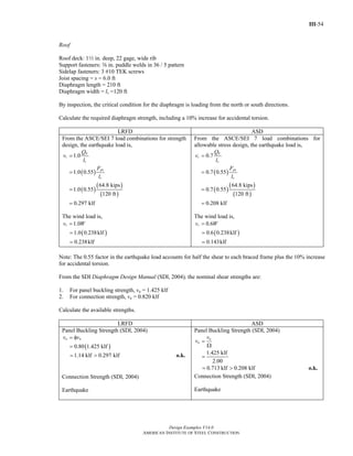
![G-
Design Examples V14.0
AMERICAN INSTITUTE OF STEEL CONSTRUCTION
19
LRFD ASD
Use Vu = φvVn to determine the required stress in the
web by dividing by the web area.
v n
w
V
A
φ
= u
w
V
A
= 2
154 kips
11.3in.
= 13.6 ksi
Use Va = Vn /Ωv to determine the required stress in the
web by dividing by the web area.
n
v w
V
AΩ
= a
w
V
A
= 2
102 kips
11.3 in.
= 9.03 ksi
Use Table 3-16a from the AISC Manual to select the required stiffener ratio a/h based on the h/tw ratio of the
girder and the required stress. Interpolate and follow an available stress curve, φvVn/Aw= 13.6 ksi for LRFD,
Vn/ΩvAw = 9.03 ksi for ASD, until it intersects the horizontal line for a h/tw value of 106. Project down from this
intersection and take the maximum a/h value of 2.00 from the axis across the bottom. Because h = 33.0 in.,
stiffeners are required at (2.00)(33.0 in.) = 66.0 in. maximum. Conservatively, use 60.0 in. spacing.
Stiffener Spacing for the Second Panel
From AISC Specification Section G3.1, tension field action is allowed because the second panel is not an end
panel.
The required shear strength at the start of the second panel, 60 in. from the end is:
LRFD ASD
[ ]
60.0in.
154 kips 1.2(0.920 klf) 1.6(2.74 klf)
12in./ft
uV
⎛ ⎞
= − + ⎜ ⎟
⎝ ⎠
= 127 kips
60.0 in
102 kips (0.920 klf + 2.74 klf)
12 in./ft
a
.
V
⎛ ⎞
= − ⎜ ⎟
⎝ ⎠
= 83.7 kips
From AISC Specification Section G1, the available shear strength without stiffeners is:
LRFD ASD
φv = 0.90
From previous calculations,
φvVn= 119 kips
119 kips < 127 kips n.g.
Therefore additional stiffeners are required.
Use Vu = φvVn to determine the required stress in the
web by dividing by the web area.
v n
w
V
A
φ
= u
w
V
A
= 2
127 kips
11.3in.
= 11.2 ksi
Ωv = 1.67
From previous calculations,
n
v
V
=
Ω
79.0 kips
79.0 kips < 83.7 kips n.g.
Therefore additional stiffeners are required.
Use Va = Vn /Ωv to determine the required stress in the
web by dividing by the web area.
n
v w
V
AΩ
= a
w
V
A
= 2
83.7 kips
11.3 in.
= 7.41 ksi
Return to Table of Contents](https://image.slidesharecdn.com/steel-construction-manual-design-examples-v14-0-pdf-151204051221-lva1-app6892/85/Steel-Construction-Manual-Design-examples-209-320.jpg)
![G-
Design Examples V14.0
AMERICAN INSTITUTE OF STEEL CONSTRUCTION
20
Use Table 3-16b from the AISC Manual, including tension field action, to select the required stiffener ratio a/h
based on the h/tw ratio of the girder and the required stress. Interpolate and follow an available stress curve,
φvVn/Aw = 11.2 ksi for LRFD, Vn/ΩvAw = 7.41 ksi for ASD, until it intersects the horizontal line for a h/tw value of
106. Because the available stress does not intersect the h/tw value of 106, the maximum value of 3.0 for a/h may
be used. Because h = 33.0 in., an additional stiffener is required at (3.0)(33.0 in.) = 99.0 in. maximum from the
previous one.
Stiffener Spacing for the Third Panel
From AISC Specification Section G3.1, tension field action is allowed because the next panel is not an end panel.
The required shear strength at the start of the third panel, 159 in. from the end is:
LRFD ASD
Vu = 154 kips − [1.2(0.920 klf) + 1.6(2.74 klf)]
×
159 in.
12 in./ft
⎛ ⎞
⎜ ⎟
⎝ ⎠
= 81.3 kips
Va = 102 kips − (0.920 klf + 2.74 klf)
159 in.
12 in./ft
⎛ ⎞
⎜ ⎟
⎝ ⎠
= 53.5 kips
From AISC Specification Section G1, the available shear strength without stiffeners is:
LRFD ASD
φv = 0.90
From previous calculations,
φvVn = 119 kips
119 kips > 81.3 kips o.k.
Therefore additional stiffeners are not required.
Ωv = 1.67
From previous calculations,
n
v
V
=
Ω
79.0 kips
79.0 kips > 53.5 kips o.k.
Therefore additional stiffeners are not required.
The four Available Shear Stress tables, AISC Manual Tables 3-16a, 3-16b, 3-17a and 3-17b, are useful because
they permit a direct solution for the required stiffener spacing. Alternatively, you can select a stiffener spacing and
check the resulting strength, although this process is likely to be iterative. In Example G.8B, the stiffener spacings
used are taken from this example.
Return to Table of Contents](https://image.slidesharecdn.com/steel-construction-manual-design-examples-v14-0-pdf-151204051221-lva1-app6892/85/Steel-Construction-Manual-Design-examples-210-320.jpg)
![G-
Design Examples V14.0
AMERICAN INSTITUTE OF STEEL CONSTRUCTION
23
Check the additional limits from AISC Specification Section G3.1 for the use of tension field action:
Note the limits of a/h ≤ 3.0 and a/h ≤ [260/(h/tw)]2
have already been calculated.
( )
( )
( )( )
2
2 11.3 in.2
2 12.0 in. 1 in.
w
fc ft
A
A A
=
+ 2
= 0.628 ≤ 2.5
33.0 in.
12.0 in.
fc ft
h h
b b
=
=
= 2.75 ≤ 6.0
Tension field action is permitted because the panel under consideration is not an end panel and the other limits
indicated in AISC Specification Section G3.1 have been met.
From AISC Specification Section G3.2,
1.10 /v yk E F =1.10 5.56(29,000 ksi / 36 ksi)
= 73.6
because / wh t > 73.6, use AISC Specification Equation G3-2
2
1
0.6
1.15 1 ( / )
v
n y w v
C
V F A C
a h
⎡ ⎤−
= +⎢ ⎥
+⎣ ⎦
(Spec. Eq. G3-2)
= ( )( )
( )
2
2
1 0.602
0.6 36 ksi 11.3 in. 0.602
1.15 1 3.00
⎡ ⎤−
⎢ ⎥+
⎢ ⎥+⎣ ⎦
= 174 kips
From AISC Specification Section G1, the available shear strength is:
LRFD ASD
φv= 0.90
φvVn = 0.90(174 kips)
= 157 kips
157 kips > 127 kips o.k.
Ωv = 1.67
174 kips
1.67
n
v
V
=
Ω
= 104 kips
104 kips > 83.7 kips o.k.
Return to Table of Contents](https://image.slidesharecdn.com/steel-construction-manual-design-examples-v14-0-pdf-151204051221-lva1-app6892/85/Steel-Construction-Manual-Design-examples-213-320.jpg)
![Design Examples V14.0
AMERICAN INSTITUTE OF STEEL CONSTRUCTION
I-13
Available Flexural Strength
According to AISC Specification Section I3.2a, the nominal flexural strength shall be determined from the plastic
stress distribution on the composite section when / 3.76 /w yh t E F≤ .
From AISC Manual Table 1-1, h/tw for a W21×50 = 49.4.
49.4 3.76 29,000 ksi / 50 ksi
90.6
≤
≤
Therefore, use the plastic stress distribution to determine the nominal flexural strength.
According to the User Note in AISC Specification Section I3.2a, this check is generally unnecessary as all current
W-shapes satisfy this limit for 50 ksi.yF ≤
Flexural strength can be determined using AISC Manual Table 3-19 or calculated directly using the provisions of
AISC Specification Chapter I. This design example illustrates the use of the Manual table only. For an illustration of
the direct calculation procedure, refer to Design Example I.2.
To utilize AISC Manual Table 3-19, the distance from the compressive concrete flange force to beam top flange, Y2,
must first be determined as illustrated by Manual Figure 3-3. Fifty percent composite action [ΣQn ≈ 0.50(AsFy)] is
used to calculate a trial value of the compression block depth, atrial, for determining Y2 as follows:
0.85
n
trial
c
Q
a
f b
∑
=
′
(from Manual. Eq. 3-7)
( )
( )( )
( )( )( )
2
0.50
0.85
0.50 14.7 in. 50 ksi
0.85 4 ksi 10.0 ft 12 in./ft
0.90 in. say 1.0 in.
s y
c
A F
f b
=
′
=
= →
Note that a trial value of 1.0 in.a = is a common starting point in many design problems.
2
2
trial
con
a
Y Y= − (from Manual. Eq. 3-6)
where
distance from top of steel beam to top of slab, in.
7.50 in.
conY =
=
1.0 in.
2 7.50 in.
2
7.00 in.
Y = −
=
Enter AISC Manual Table 3-19 with the required strength and Y2 = 7.00 in. to select a plastic neutral axis location for
the W21×50 that provides sufficient available strength.
Selecting PNA location 5 (BFL) with 386 kipsnQ∑ = provides a flexural strength of:
Return to Table of Contents](https://image.slidesharecdn.com/steel-construction-manual-design-examples-v14-0-pdf-151204051221-lva1-app6892/85/Steel-Construction-Manual-Design-examples-257-320.jpg)

1.0[750 kip-ft 22.6 kips(10.0 ft 6.78 ft)
677 kip-ft 750 kip-ft
677 kip-ft 624 kip-ft
]
b n b b px b b p b px
b n u
M C M BF L L M
M M
φ = φ − φ − ≤ φ
= − −
= ≤
φ ≥
> o.k.
( )
( )
1.0[499 kip-ft 15.1 kips 10.0 ft 6.78 ft
450 kip-ft 499 kip-ft
450 kip-ft 482 kip-ft
]
px pxn
b b p
b b b b
n
a
b
M MM BF
C L L
M
M
⎡ ⎤
= − − ≤⎢ ⎥Ω Ω Ω Ω⎣ ⎦
= − −
= ≤
≥
Ω
< n.g.
For this example, the relatively low live load to dead load ratio results in a lighter member when LRFD methodology
is employed. When ASD methodology is employed, a heavier member is required, and it can be shown that a W24×84
is adequate for pre-composite flexural strength. This example uses a W24×76 member to illustrate the determination
of flexural strength of the composite section using both LRFD and ASD methodologies; however, this is done for
comparison purposes only, and calculations for a W24×84 would be required to provide a satisfactory ASD design.
Calculations for the heavier section are not shown as they would essentially be a duplication of the calculations
provided for the W24×76 member.
Note that for the member size chosen, 76 lb/ft 80 lb/ft,≤ thus the initial weight assumption is adequate.
From AISC Manual Table 1-1, the geometric properties are as follows:
W24×76
A = 22.4 in.2
Ix = 2,100 in.4
bf = 8.99 in.
tf = 0.680 in.
d = 23.9 in.
Return to Table of Contents](https://image.slidesharecdn.com/steel-construction-manual-design-examples-v14-0-pdf-151204051221-lva1-app6892/85/Steel-Construction-Manual-Design-examples-265-320.jpg)
![Design Examples V14.0
AMERICAN INSTITUTE OF STEEL CONSTRUCTION
I-24
(2) one-half the distance to the centerline of the adjacent girder
( )
45 ft
2 sides 45.0 ft
2
=
(3) distance to the edge of the slab
not applicable for an interior member
Available Flexural Strength
According to AISC Specification Section I3.2a, the nominal flexural strength shall be determined from the plastic
stress distribution on the composite section when / 3.76 /w yh t E F≤ .
From AISC Manual Table 1-1, h/tw for a W24×76 = 49.0.
49.0 3.76 29,000 ksi / 50 ksi
90.6
≤
≤
Therefore, use the plastic stress distribution to determine the nominal flexural strength.
According to the User Note in AISC Specification Section I3.2a, this check is generally unnecessary as all current
W-shapes satisfy this limit for 50 ksi.yF ≤
AISC Manual Table 3-19 can be used to facilitate the calculation of flexural strength for composite beams.
Alternately, the available flexural strength can be determined directly using the provisions of AISC Specification
Chapter I. Both methods will be illustrated for comparison in the following calculations.
Method 1: AISC Manual
To utilize AISC Manual Table 3-19, the distance from the compressive concrete flange force to beam top flange, Y2,
must first be determined as illustrated by Manual Figure 3-3. Fifty percent composite action [ΣQn ≈ 0.50(AsFy)] is
used to calculate a trial value of the compression block depth, atrial, for determining Y2 as follows:
0.85
n
trial
c
Q
a
f b
∑
=
′
(from Manual. Eq. 3-7)
( )
( )( )
( )( )( )
2
0.50
0.85
0.50 22.4 in. 50 ksi
0.85 4 ksi 7.50 ft 12 in./ft
1.83 in.
s y
c
A F
f b
=
′
=
=
2
2
trial
con
a
Y Y= − (from Manual. Eq. 3-6)
where
distance from top of steel beam to top of slab
7.50 in.
conY =
=
Return to Table of Contents](https://image.slidesharecdn.com/steel-construction-manual-design-examples-v14-0-pdf-151204051221-lva1-app6892/85/Steel-Construction-Manual-Design-examples-268-320.jpg)

![Design Examples V14.0
AMERICAN INSTITUTE OF STEEL CONSTRUCTION
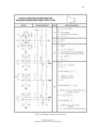
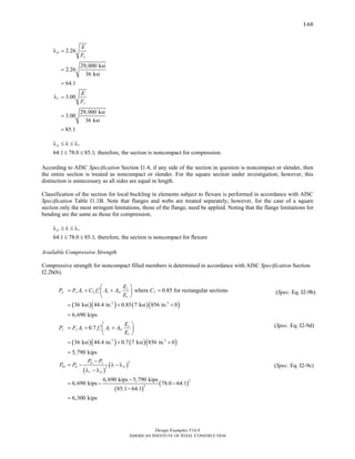
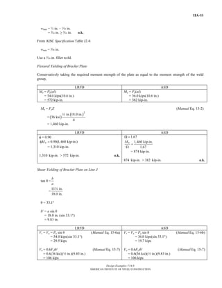
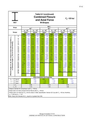
I-86
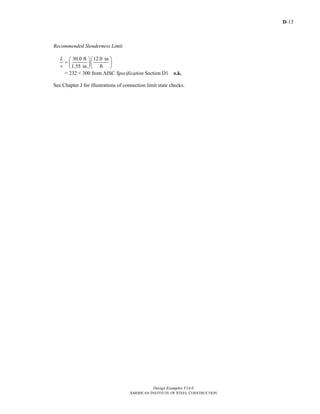
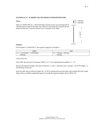
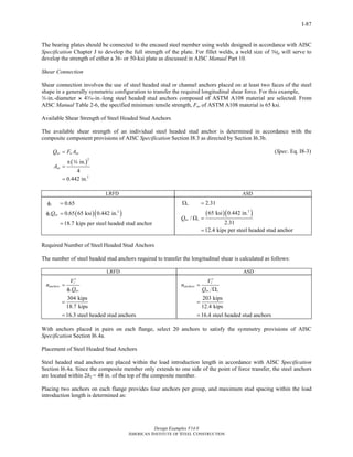
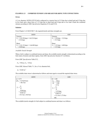
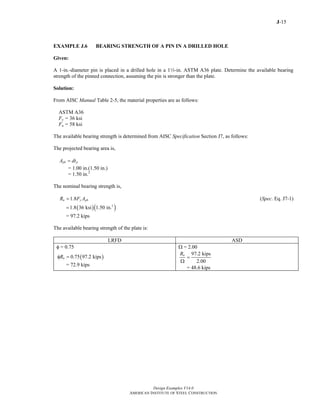
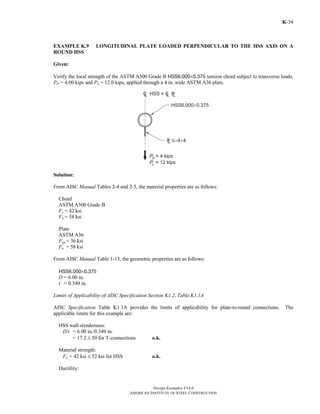
Fig. I.8-3. Internal bearing plate yield line pattern (fixed condition).
The plate thickness using 36 ksiyF = material may be determined as:
LRFD ASD
( )
( )
( )
( )
2
2
0.90
If :
2 3 2
4
If :
2 3 2
6
p f
u
p
y
p f
u
p
y
t t
a w b a
t
F a b
t t
a w b a
t
F a b
φ =
≥
−
=
3φ +
<
−
=
3φ +
where
1
2
bearing pressure on plate determined
using LRFD load combinations
304 kips
134 in.
2.27 ksi
u
r
w
V
A
=
′
=
=
=
Assuming tp ≥ tf
( ) ( ) ( ) ( )[ ]
( )( ) ( )[ ]
2
2 3.84 in. 2.27 ksi 3 8.86 in. 2 3.84 in.
36ksi 4 3.84 in. 8.86 in.
0.733 in.
pt
−
=
3 0.90 +
=
Select w-in. plate.
in. 0.620 in.p ft t= > = assumption o.k.w
( )
( )
( )
( )
2
2
1.67
If :
3 2
3 4
If :
3 2
3 6
p f
u
p
y
p f
u
p
y
t t
a w b a
t
F a b
t t
a w b a
t
F a b
Ω =
≥
⎡ ⎤−⎛ ⎞2Ω
= ⎢ ⎥⎜ ⎟
+⎢ ⎥⎝ ⎠ ⎣ ⎦
<
⎡ ⎤−⎛ ⎞2Ω
= ⎢ ⎥⎜ ⎟
+⎢ ⎥⎝ ⎠ ⎣ ⎦
where
1
2
bearing pressure on plate determined
using ASD load combinations
203 kips
134 in.
1.51 ksi
u
r
w
V
A
=
′
=
=
=
Assuming tp ≥ tf
( )( ) ( ) ( ) ( )[ ]
( ) ( )[ ]
2
2 1.67 3.84 in. 1.51ksi 3 8.86 in. 2 3.84 in.
3 36 ksi 4 3.84 in. 8.86 in.
0.733 in.
pt
−
=
+
=
Select w-in. plate
in. 0.620 in.p ft t= > = assumption o.k.w
Thus, select w-in.-thick bearing plates.
Bearing Plate to Encased Steel Member Weld
Return to Table of Contents](https://image.slidesharecdn.com/steel-construction-manual-design-examples-v14-0-pdf-151204051221-lva1-app6892/85/Steel-Construction-Manual-Design-examples-330-320.jpg)
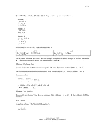
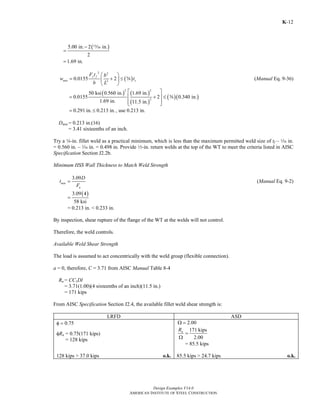
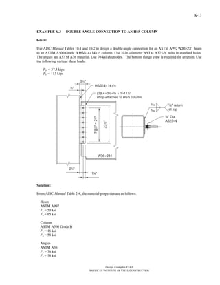
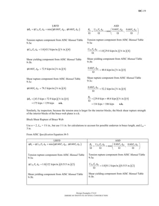
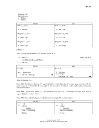
0.6 ( in.)u h sF L n d t= − +z
= 0.6(65 ksi)[11.5 in. – 4(m in. + z in.)](0.340 in.)
= 106 kips
LRFD ASD
φRn = 0.75(106 kips)
= 79.5 kips
106 kips
2.00
nR
=
Ω
= 53.0 kips
79.5 kips > 37.0 kips o.k. 53.0 kips > 24.7 kips o.k.
Stem Block Shear Rupture Strength
Determine the available strength for the limit state of block shear rupture from AISC Specification Section J4.3.
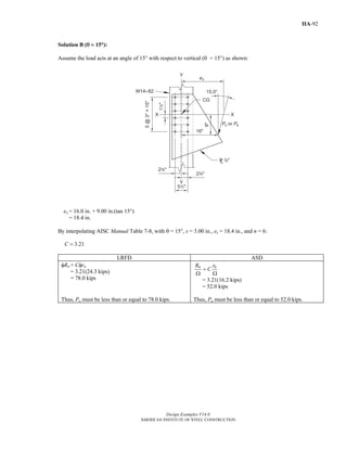
For this case Ubs = 1.0.
Use AISC Manual Tables 9-3a, 9-3b and 9-3c. Assume Leh = 1.99 in. ≈ 2.00 in.
Return to Table of Contents](https://image.slidesharecdn.com/steel-construction-manual-design-examples-v14-0-pdf-151204051221-lva1-app6892/85/Steel-Construction-Manual-Design-examples-391-320.jpg)
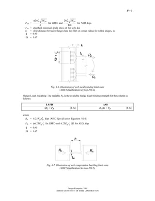
![Design Examples V14.0
AMERICAN INSTITUTE OF STEEL CONSTRUCTION
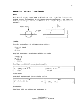
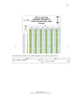
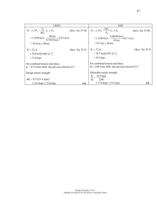
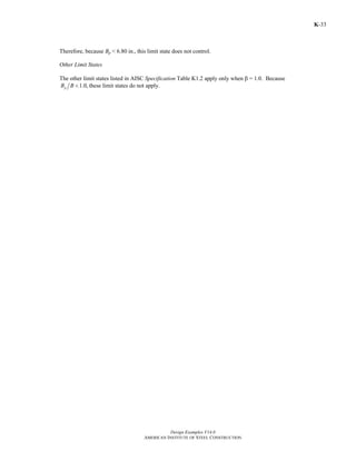
K-25
HSS6×6×a
B = H = 6.00 in.
t = 0.349 in.
b/t = 14.2
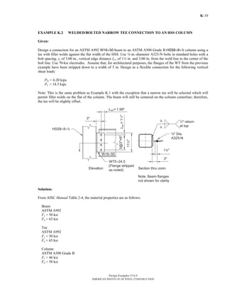
From Chapter 2 of ASCE/SEI 7, the required strength is:
LRFD ASD
( ) ( )1.2 6.50 kips 1.6 19.5 kipsuR = +
= 39.0 kips
6.50 kips 19.5 kipsaR = +
26.0 kips=
Limits of Applicability of AISC Specification Section K1.3
AISC Specification Table K1.2A gives the following limits of applicability for plate-to-rectangular HSS
connections. The limits applicable here are:
HSS wall slenderness:
( 3 )
1.40
[6.00 in. 3(0.349in.)] 29,000 ksi
1.40
0.349in. 46 ksi
y
B t E
t F
−
≤
−
≤
14.2 < 35.2 o.k.
Material Strength:
46 ksi 52 ksiyF = ≤ o.k.
Ductility:
46 ksi
58 ksi
y
u
F
F
=
= 0.793 ≤ 0.8 o.k.
Using AISC Manual Part 10, determine if a single-plate connection is suitable (the HSS wall is not slender).
Maximum Single-Plate Thickness
From AISC Specification Table K1.2, the maximum single-plate thickness is:
u
p
yp
F
t t
F
≤ (Spec. Eq. K1-3)
58 ksi
(0.349 in.)
36 ksi
=
= 0.562 in.
Note: Limiting the single-plate thickness precludes a shear yielding failure of the HSS wall.
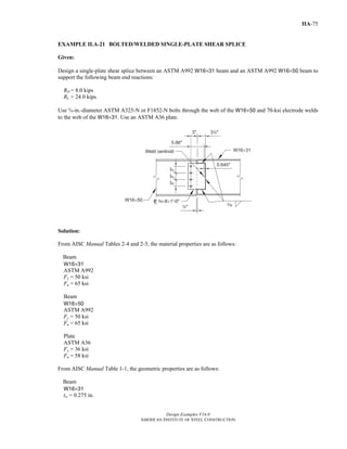
Single-Plate Connection
Try 3 bolts and a c-in. plate thickness with 4-in. fillet welds.
in. 0.562 in.pt = <c o.k.
Return to Table of Contents](https://image.slidesharecdn.com/steel-construction-manual-design-examples-v14-0-pdf-151204051221-lva1-app6892/85/Steel-Construction-Manual-Design-examples-411-320.jpg)
![Design Examples V14.0
AMERICAN INSTITUTE OF STEEL CONSTRUCTION
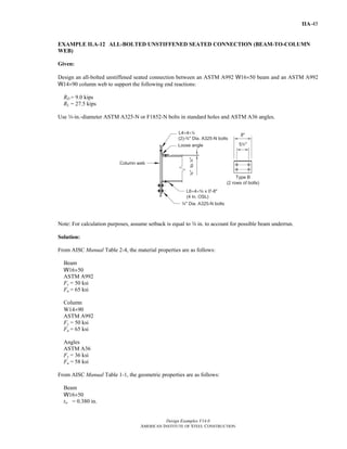
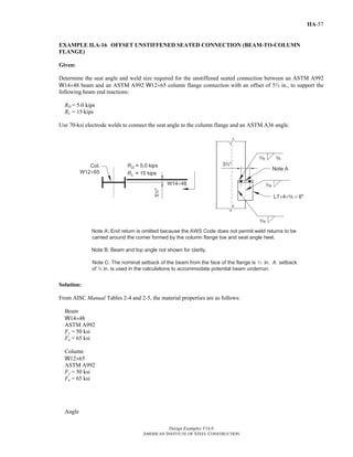
IIA-29
1.65
2.2
oh
k
c
⎛ ⎞
= ⎜ ⎟
⎝ ⎠
(Manual Eq. 9-10)
=
1.65
9.90 in.
2.2
5.00 in.
⎛ ⎞
⎜ ⎟
⎝ ⎠
= 6.79
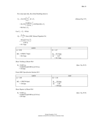
For top cope only, the critical buckling stress is:
2
26,210 w
cr
o
t
F f k
h
⎛ ⎞
= ⎜ ⎟
⎝ ⎠
yF≤ (Manual Eq. 9-7)
( )( )
2
0.295 in.
26,210 0.840 6.79
9.90 in.
⎛ ⎞
= ⎜ ⎟
⎝ ⎠
133 ksi yF= ≤
Use Fcr = Fy = 50 ksi.
From AISC Manual Equation 9-6:
LRFD ASD
φ = 0.90
cr net
n
F S
R
e
φ
φ =
=
( )( )3
0.90 50 ksi 8.03 in.
5.50 in.
= 65.7 kips > 25.0 kips o.k.
Ω = 1.67
n cr netR F S
e
=
Ω Ω
=
( )
( )
3
50 ksi 8.03 in.
1.67 5.50 in.
= 43.7 kips > 16.7 kips o.k.
Shear Yielding of Beam Web
Rn = 0.60FyAgv (Spec. Eq. J4-3)
= 0.60(50 ksi)(0.295 in.)(9.90 in.)
= 87.6 kips
From AISC Specification Section J4.2:
LRFD ASD
φ = 1.00
1.00(87.6 kips)nRφ =
87.6 kips > 25.0 kips= o.k.
Ω = 1.50
87.6 kips
1.50
nR
=
Ω
58.4kips > 16.7 kips= o.k.
Shear Rupture of Beam Web
Anv = tw[ho – 2(m in.+ z in.)]
= 0.295 in.(9.90 in. – 1.75 in.)
= 2.40 in.2
Rn = 0.60FuAnv (Spec. Eq. J4-4)
= 0.60(65 ksi)(2.40 in.2
)
Return to Table of Contents](https://image.slidesharecdn.com/steel-construction-manual-design-examples-v14-0-pdf-151204051221-lva1-app6892/85/Steel-Construction-Manual-Design-examples-464-320.jpg)
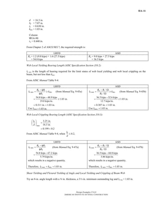
![Design Examples V14.0
AMERICAN INSTITUTE OF STEEL CONSTRUCTION
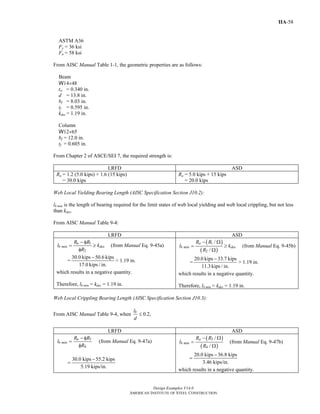
IIA-32
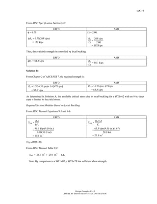
Rn = 0.60FyAgv (Spec. Eq. J4-3)
= 0.60(50 ksi)(0.380 in.)(18.8 in.)
= 214 kips
From AISC Specification Section J4.2:
LRFD ASD
φ = 1.00
( )1.00 214 kips
214 kips > 110 kips
nRφ =
= o.k.
Ω = 1.50
214 kips
1.50
143 kips > 73.3 kips
nR
=
Ω
= o.k.
Shear Rupture of Beam Web
Anv = tw[ho – (5)(m in. + z in.)]
= 0.380 in.(18.8 in. – 4.38 in.)
= 5.48 in.2
Rn = 0.60FuAnv (Spec. Eq. J4-4)
= 0.60(65 ksi)(5.48 in.2
)
= 214 kips
From AISC Specification Section J4.2:
LRFD ASD
φ = 0.75
( )0.75 214 kips
161 kips > 110 kips
nRφ =
= o.k.
Ω = 2.00
214 kips
2.00
107 kips > 73.3 kips
nR
=
Ω
= o.k.
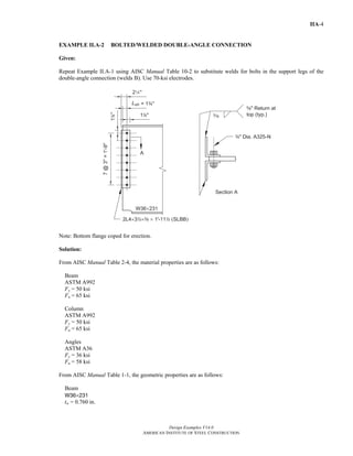
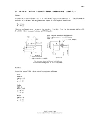
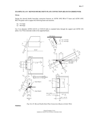
Supporting Girder
Supporting Girder Web
The required bearing strength per bolt is greatest for the bolts that are loaded by both connections. Thus, for the
design of these four critical bolts, the required strength is determined as follows:
LRFD ASD
From Beam A, each bolt must support one-fourth of
25.0 kips or 6.25 kips/bolt.
From Beam B, each bolt must support one-tenth of 110
kips or 11.0 kips/bolt.
Thus,
Ru = 6.25 kips/bolt + 11.0 kips/bolt
= 17.3 kips/bolt
From AISC Manual Table 7-4, the allowable bearing
strength per bolt is:
From Beam A, each bolt must support one-fourth of
16.7 kips or 4.18 kips/bolt.
From Beam B, each bolt must support one-tenth of 73.3
kips or 7.33 kips/bolt.
Thus,
Ra = 4.18 kips/bolt + 7.33 kips/bolt
= 11.5 kips/bolt
From AISC Manual Table 7-4, the allowable bearing
strength per bolt is:
Return to Table of Contents](https://image.slidesharecdn.com/steel-construction-manual-design-examples-v14-0-pdf-151204051221-lva1-app6892/85/Steel-Construction-Manual-Design-examples-467-320.jpg)

![Design Examples V14.0
AMERICAN INSTITUTE OF STEEL CONSTRUCTION
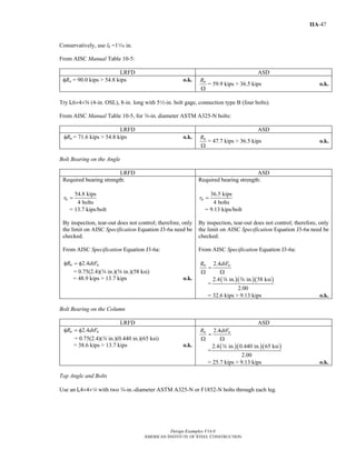
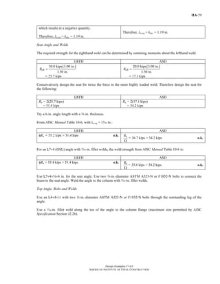
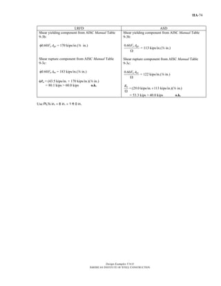
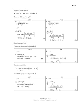
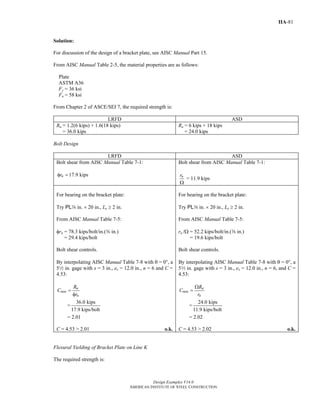
IIA-73
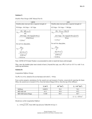
Shear Yielding of Plate
From AISC Specification Equation J4-3:
LRFD ASD
φ = 1.00
0.60
1.00(0.60)(36 ksi)(12.0 in.)( in.)
97.2 kips > 60.0 kips
n y gvR F Aφ = φ
=
= o.k.
a
Ω = 1.50
0.60
0.60(36 ksi)(12.0 in.)( in.)
1.50
64.8 kips > 40.0 kips
y gvn F AR
=
Ω Ω
=
= o.k.
a
Shear Rupture of Plate
Anv = a in.[12.0 in. – 4(, in. + z in.)]
= 3.00 in.2
From AISC Specification Equation J4-4:
LRFD ASD
φ = 0.75
0.60n u nvR F Aφ = φ
= ( )( )( )2
0.75 0.60 58 ksi 3.00in.
= 78.3 kips > 60.0 kips o.k.
Ω = 2.00
0.60n u nvR F A
=
Ω Ω
=
( )( )2
0.60 58 ksi 3.00 in.
2.00
= 52.2 kips > 40.0 kips o.k.
Block Shear Rupture of Plate
Leh = Lev = 12 in.
From AISC Specification Equation J4-5:
LRFD ASD
min( 0.60 , 0.60 )n bs u nt y gv u nvR U F A F A F Aφ = φ + φ φ
Ubs = 1.0
0.60 0.60
min ,
y gvn bs u nt u nvF AR U F A F A⎛ ⎞
= + ⎜ ⎟Ω Ω Ω Ω⎝ ⎠
Ubs = 1.0
Tension rupture component from AISC Manual Table
9-3a:
bs u ntU F Aφ = 1.0(43.5 kips/in.)(a in.)
Tension rupture component from AISC Manual Table
9-3a:
bs u ntU F A
Ω
= 1.0(29.0 kips/in.)(a in.)
Return to Table of Contents](https://image.slidesharecdn.com/steel-construction-manual-design-examples-v14-0-pdf-151204051221-lva1-app6892/85/Steel-Construction-Manual-Design-examples-508-320.jpg)
![Design Examples V14.0
AMERICAN INSTITUTE OF STEEL CONSTRUCTION
IIA-102
LRFD ASD
=
39.8 kips
16.5 kips/bolt
= 2.41
Try a four-bolt connection.
From AISC Manual Table 10-11:
C = 3.07 > 2.41 o.k.
=
26.5 kips
11.0 kips/bolt
= 2.41
Try a four-bolt connection.
From AISC Manual Table 10-11:
C = 3.07 > 2.41 o.k.
The 3-in. leg will be shop bolted to the girder web and the 4-in. leg will be field bolted to the beam web.
Shear Yielding of Angle
Rn = 0.60FyAgv (Spec. Eq. J4-3)
= 0.60(36 ksi)(112 in.)(a in.)
= 93.2 kips
From AISC Specification Section J4.2:
LRFD ASD
φ = 1.00
φRn = 1.00(93.2 kips)
= 93.2 kips > 39.8 kips o.k.
Ω = 1.50
93.2 kips
1.50
62.1 kips > 26.5
nR
=
Ω
= o.k.
Shear Rupture of Angle
Anv = a in.[112 in. − 4(m in. + z in.)]
= 3.00 in.2
Rn = 0.60FuAnv (Spec. Eq. J4-4)
= 0.60(58 ksi)(3.00 in.2
)
= 104 kips
From AISC Specification Section J4.2:
LRFD ASD
φ = 0.75
φRn = 0.75(104 kisp)
= 78.0 kips > 39.8 kips o.k.
Ω = 2.00
104 kips
2.00
nR
=
Ω
= 52.0 kips > 26.5 kips o.k.
Block Shear Rupture of Angle
n = 4
Lev = Leh = 14 in.
From AISC Specification Equation J4-5:
Return to Table of Contents](https://image.slidesharecdn.com/steel-construction-manual-design-examples-v14-0-pdf-151204051221-lva1-app6892/85/Steel-Construction-Manual-Design-examples-537-320.jpg)
![Design Examples V14.0
AMERICAN INSTITUTE OF STEEL CONSTRUCTION
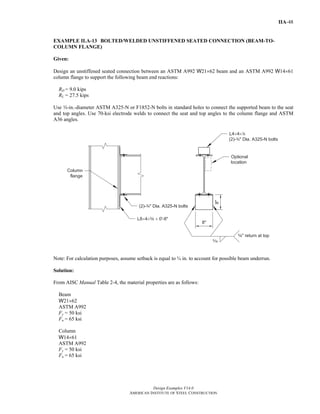
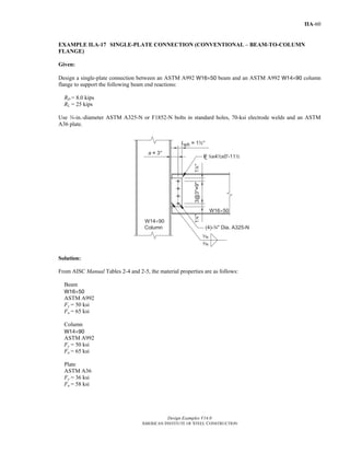
IIA-114
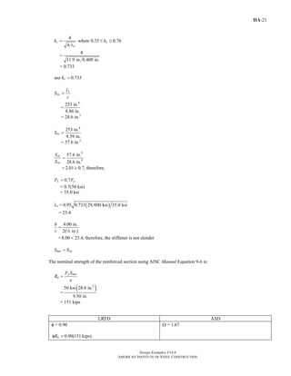
=
1 27.5 kips/bolt
1
2.02 8.55 kips/bolt
⎛ ⎞
−⎜ ⎟
⎝ ⎠
= 1.10
=
1 18.3 kips/bolt
1
2.02 5.70 kips/bolt
⎛ ⎞
−⎜ ⎟
⎝ ⎠
= 1.09
Since 1β ≥ , set α′ = 1.0
p = 14 in. +
3.00 in.
2
= 2.75 in.
≤ s = 3.00 in.
'
1
d
p
δ = − (Manual Eq. 9-24)
=
in.
1
2.75 in.
−
m
= 0.705
LRFD ASD
φ = 0.90
( )
4 '
1 '
u
min
u
T b
t
pF
=
φ + δα
(Manual Eq. 9-23a)
=
[ ]
4(8.55 kips)(2.57 in.)
0.90(2.75 in.)(65 ksi) 1 (0.705)(1.0)+
= 0.566 in. < 0.620 in. o.k.
Ω = 1.67
( )
4 '
1 '
a
min
u
T b
t
pF
Ω
=
+ δα
(Manual Eq. 9-23b)
=
[ ]
1.67(4)(5.70 kips)(2.57 in.)
2.75 in.(65 ksi) 1 (0.705)(1.0)+
= 0.567 in. < 0.620 in. o.k.
Similarly, checks of the tee flange for shear yielding, shear rupture, and block shear rupture will show that the tee
flange is o.k.
Bolt Bearing on Beam Web
From AISC Manual Table 10-1, for four rows of w-in.-diameter bolts and an uncoped beam:
LRFD ASD
φRn = 351 kips/in.(0.380 in.)
= 133 kips > 54.0 kips o.k.
nR
Ω
= 234 kips/in.(0.380 in.)
= 88.9 kips > 36.0 kips o.k.
Bolt Bearing on Column Flange
From AISC Manual Table 10-1, for four rows of w-in.-diameter bolts:
LRFD ASD
φRn = 702 kips/in.(0.710 in.)
= 498 kips > 54.0 kips o.k.
nR
Ω
= 468 kips/in.(0.710 in.)
= 332 kips > 36.0 kips o.k.
Note: Although the edge distance (a = 0.895 in.) for one row of bolts in the tee flange does not meet the minimum
value indicated in AISC Specification Table J3.4, based on footnote [a], the edge distance provided is acceptable
because the provisions of AISC Specification Section J3.10 and J4.4 have been met in this case.
Return to Table of Contents](https://image.slidesharecdn.com/steel-construction-manual-design-examples-v14-0-pdf-151204051221-lva1-app6892/85/Steel-Construction-Manual-Design-examples-549-320.jpg)
![Design Examples V14.0
AMERICAN INSTITUTE OF STEEL CONSTRUCTION
IIA-119
Shear Rupture of Tee Stem
[ ]11 in. 4( in. in.) (0.350 in.)nvA = − +2 m z
= 2.80 in.2
From AISC Specification Equation J4-4:
LRFD ASD
φ = 0.75
φRn = 0.60 u nvF Aφ
= 2
0.75(0.60)(65 ksi)(2.80in. )
= 81.9 kips > 36.0 kips o.k.
Ω = 2.00
0.60n u nvR F A
=
Ω Ω
=
2
0.60(65 ksi)(2.80in. )
2.00
= 54.6 kips > 24.0 kips o.k.
Block Shear Rupture of Tee Stem
Leh = Lev = 14 in.
From AISC Specification Equation J4-5:
LRFD ASD
min( 0.60 , 0.60 )n bs u nt y gv u nvR U F A F A F Aφ = φ + φ φ
Ubs = 1.0
0.60 0.60
min ,
y gvn bs u nt u nvF AR U F A F A⎛ ⎞
= + ⎜ ⎟
Ω Ω Ω Ω⎝ ⎠
Ubs = 1.0
Tension rupture component from AISC Manual Table
9-3a:
bs u ntU F Aφ = 1.0(39.6 kips/in.)(0.350 in.)
Shear yielding component from AISC Manual Table
9-3b:
0.60 y gvF Aφ = 231 kips/in.(0.350 in.)
Shear rupture component from AISC Manual Table
9-3c:
0.60 u nvF Aφ = 210 kips/in.(0.350 in.)
φRn = (39.6 kips/in + 210 kips/in.)(0.350in.)
= 87.4 kips > 36.0 kips o.k.
Tension rupture component from AISC Manual Table
9-3a:
bs u ntU F A
Ω
= 1.0(26.4 kips/in.)(0.350 in.)
Shear yielding component from AISC Manual Table
9-3b:
0.60 y gvF A
Ω
= 154 kips/in.(0.350 in.)
Shear rupture component from AISC Manual Table
9-3c:
0.60 u nvF A
Ω
= 140 kips/in.(0.350 in.)
nR
=
Ω
(26.4 kips/in. + 140 kips/in.)(0.350 in.)
= 58.2 kips > 24.0 kips o.k.
Return to Table of Contents](https://image.slidesharecdn.com/steel-construction-manual-design-examples-v14-0-pdf-151204051221-lva1-app6892/85/Steel-Construction-Manual-Design-examples-554-320.jpg)


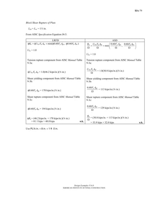
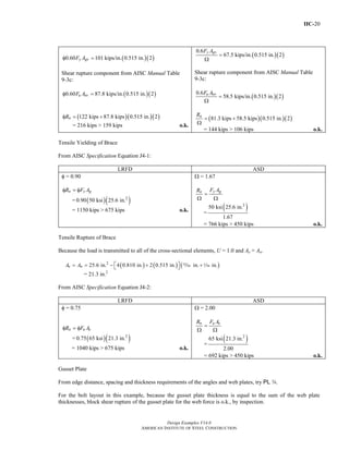
= 3.00 in.2
( )( )( )2
0.75 1.0 58 ksi 3.00 in.bs u ntU F Aφ =
= 131 kips
Shear yielding component from AISC Manual Table
9-3b with Lev = 12 in.:
0.60 y gvF Aφ = 170 kips/in.(w in.)
Shear rupture component from AISC Manual Table
9-3c with Lev = 12 in.:
0.60 u nvF Aφ = 183 kips/in.(w in.)
Shear yielding controls, thus,
131 kips 170 kips/in.( in.)nRφ = + w
= 259 kips > 161 kips o.k.
Case 3:
From AISC Specification Equation J4-5:
0.60 0.60
min ,
y gvn bs u nt u nvF AR U F A F A⎛ ⎞
= + ⎜ ⎟
Ω Ω Ω Ω⎝ ⎠
Ubs = 1.0
Tension component:
Ant = [5.50 in. – 1.5(, in. + z in.)](w in.)
= 3.00 in.2
( )( )2
1.0 58 ksi 3.00 in.
2.00
bs u ntU F A
=
Ω
= 87.0 kips
Shear yielding component from AISC Manual Table
9-3b with Lev = 12 in.:
0.60 /y gvF A Ω = 113 kips/in.(w in.)
Shear rupture component from AISC Manual Table
9-3c with Lev = 12 in.:
0.60 /u nvF A Ω = 122 kips/in.(w in.)
Shear yielding controls, thus,
( )87.0 kips 113 kips/in. in.nR
= +
Ω
w
= 172 kips > 108 kips o.k.
Block Shear Rupture of the Beam Flange
This case involves the tearout of the two blocks outside the two rows of bolt holes in the flanges; for this case Leh
= 1w in. and Lev = 12 in. (Use 14 in. to account for possible underrun in beam length.)
LRFD ASD
From AISC Specification Equation J4-5:
( )min 0.60 , 0.60n bs u nt y gv u nvR U F A F A F Aφ = φ + φ φ
Ubs = 1.0
Tension component from AISC Manual Table 9-3a:
bs u ntU F Aφ = 1.0(60.9 kips/in.)(0.570 in.)(2)
From AISC Specification Equation J4-5:
0.60 0.60
min ,
y gvn bs u nt u nvF AR U F A F A⎛ ⎞
= + ⎜ ⎟
Ω Ω Ω Ω⎝ ⎠
Ubs = 1.0
Tension component from AISC Manual Table 9-3a:
/bs u ntU F A Ω = 1.0(40.6 kips/in.)(0.570 in.)(2)
Return to Table of Contents](https://image.slidesharecdn.com/steel-construction-manual-design-examples-v14-0-pdf-151204051221-lva1-app6892/85/Steel-Construction-Manual-Design-examples-564-320.jpg)
![IIB-13
Design Examples V14.0
AMERICAN INSTITUTE OF STEEL CONSTRUCTION
LRFD ASD
1 22( ) ( )n bR R l Rφ = φ + φ (Manual Eq. 9-46a)
2(83.7 kips) + 0.750 in.(24.3 kips/in.)=
186 kips > 161 kips= o.k.
1 2
2
n
b
R R R
l
⎛ ⎞ ⎛ ⎞
= +⎜ ⎟ ⎜ ⎟Ω Ω Ω⎝ ⎠ ⎝ ⎠
(Manual Eq. 9-46b)
2(55.8 kips) 0.750 in.(16.2 kips/in.)= +
124 kips 108 kips= > o.k.
Web Crippling (AISC Specification Section J10.3)
Assume the concentrated force to be resisted is applied at a distance from the member end that is greater than or
equal to d/2.
From AISC Manual Table 9-4:
LRFD ASD
[ ]3 42 ( ) ( )n bR R l Rφ = φ + φ (Manual Eq. 9-49a)
[ ]2 (108 kips) 0.750 in.(11.2 kips/in.)= +
233 kips > 161 kips= o.k.
3 4
2
n
b
R R R
l
⎡ ⎤⎛ ⎞ ⎛ ⎞
= +⎢ ⎥⎜ ⎟ ⎜ ⎟Ω Ω Ω⎝ ⎠ ⎝ ⎠⎣ ⎦
(Manual Eq. 9-49b)
[ ]2 (71.8 kips) 0.750 in.(7.44 kips/in.)= +
155 kips 108 kips= > o.k.
Note: Web compression buckling (AISC Specification Section J10.5) must be checked if another beam is framed
into the opposite side of the column at this location.
Web panel zone shear (AISC Specification Section J10.6) should also be checked for this column.
For further information, see AISC Design Guide 13 Stiffening of Wide-Flange Columns at Moment Connections:
Wind and Seismic Applications (Carter, 1999).
Return to Table of Contents](https://image.slidesharecdn.com/steel-construction-manual-design-examples-v14-0-pdf-151204051221-lva1-app6892/85/Steel-Construction-Manual-Design-examples-567-320.jpg)

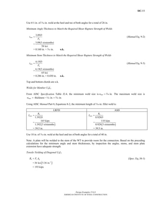
= 5.25 in.2
LRFD ASD
φ = 0.75
φRn = φ0.6FupAn >
2
fuF
(from Design Guide 4 Eq. 3.13)
= 0.75(0.6)(58 ksi)(5.25 in.2
) >
173 kips
2
= 137 kips > 86.5 kips o.k.
Ω = 2.00
0.6
2
up n fan F A FR
= >
Ω Ω
(from Design Guide 4 Eq. 3.13)
=
( )( )2
0.6 58 ksi 5.25 in. 116 kips
2.00 2
>
= 91.4 kips > 58.0 kips o.k.
Note: For the vertical shear forces, the shear yielding strength, shear rupture strength, and flexural yielding
strength of the end-plate are all adequate by inspection.
Bolt Shear and Bearing
Try the minimum of four bolts at the tension flange and two bolts at the compression flange.
Note: Based on common practice, the compression bolts are assumed to resist all of the shear force.
Return to Table of Contents](https://image.slidesharecdn.com/steel-construction-manual-design-examples-v14-0-pdf-151204051221-lva1-app6892/85/Steel-Construction-Manual-Design-examples-580-320.jpg)
![IIB-30
Design Examples V14.0
AMERICAN INSTITUTE OF STEEL CONSTRUCTION
Trial Bolt Diameter and Maximum Prying Forces
Try 1-in.-diameter bolts.
( )' in.
2
p
b
b
w d= − +z (Design Guide 16 Eq. 2-12)
= ( )
7.50 in.
1.00 in. + in.
2
− z
= 2.69 in.
3
3.62 0.085
p
i
b
t
a
d
⎛ ⎞
= −⎜ ⎟
⎝ ⎠
(Design Guide 16 Eq. 2-13)
=
3
in.
3.62 0.085
1.00 in.
⎛ ⎞
−⎜ ⎟
⎝ ⎠
d
= 2.34 in.
3
2
,
0.85 0.80 '
2 8
'
4
p b nt
p py
i
f i
b d F
t F w
F
p
⎡ ⎤ π⎛ ⎞
+ +⎢ ⎥⎜ ⎟
⎝ ⎠⎣ ⎦= (Design Guide 16 Eq. 2-14)
=
( ) ( ) ( )
( ) ( )
( )
3
2 1.00 in. 90 ksi7.50 in.
in. 36ksi 0.85 0.80 2.69 in.
2 8
4 1 in.
π⎡ ⎤⎛ ⎞
+ +⎜ ⎟⎢ ⎥
⎝ ⎠⎣ ⎦
d
2
= 30.4 kips
22
2' '
3
4 '
p i
max,i py
i p
w t F
Q F
a w t
⎛ ⎞
= − ⎜ ⎟⎜ ⎟
⎝ ⎠
(Design Guide 16 Eq. 2-11)
=
( )
( )
( )
( )
22
22.69in. in. 30.4 kips
36 ksi 3
4 2.38 in. 2.69 in. in.
⎛ ⎞
− ⎜ ⎟⎜ ⎟
⎝ ⎠
d
d
= 6.10 kips
,min ,o i ext f oa a p p= −⎡ ⎤⎣ ⎦ (Design Guide 16 Eq. 2-16)
= [ ]min 2.34 in., (3.00 in. 1 in.)− 2
= 1.50 in.
From AISC Design Guide 16 Equation 2-17:
,
,
' '
f i
o i
f o
p
F F
p
⎛ ⎞
= ⎜ ⎟⎜ ⎟
⎝ ⎠
=
1 in.
30.4 kips
1 in.
⎛ ⎞
⎜ ⎟
⎝ ⎠
2
2
= 30.4 kips
Return to Table of Contents](https://image.slidesharecdn.com/steel-construction-manual-design-examples-v14-0-pdf-151204051221-lva1-app6892/85/Steel-Construction-Manual-Design-examples-584-320.jpg)

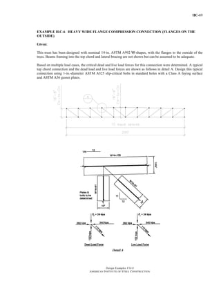
![IIC-29
Design Examples V14.0
AMERICAN INSTITUTE OF STEEL CONSTRUCTION
2
bd
b b′ = − (Manual Eq. 9-21)
=
in.
2.69 in.
2
−
d
= 2.25 in.
' 1.25 in.
2 2
b bd d
a a b
⎛ ⎞
= + ≤ +⎜ ⎟
⎝ ⎠
(Manual Eq. 9-27)
=
in. in.
2.00 in. + 1.25(2.69 in.)+
2 2
≤
d d
= 2.44 in. 3.80 in.≤
b
a
′
ρ =
′
(Manual Eq. 9-26)
=
2.25 in.
2.44 in.
= 0.922
LRFD ASD
1
1u
u
B
T
⎛ ⎞
β = −⎜ ⎟ρ ⎝ ⎠
(Manual Eq. 9-25)
=
1 30.2 kips/bolt
1
0.922 8.55 kips/bolt
⎛ ⎞
−⎜ ⎟
⎝ ⎠
= 2.75
1
1a
a
B
T
⎛ ⎞
β = −⎜ ⎟ρ ⎝ ⎠
(Manual Eq. 9-25)
=
1 20.2 kips/bolt
1
0.922 5.70 kips/bolt
⎛ ⎞
−⎜ ⎟
⎝ ⎠
= 2.76
Because 1, set ' = 1.0.β > α
'
1
d
p
δ = − (Manual Eq. 9-24)
=
in.
1
3.00 in.
−
,
= 0.688
LRFD ASD
φ = 0.90
4
(1 )
u
req
u
T b
t
pF
′
=
′φ + δα
(Manual Eq. 9-23a)
=
[ ]
4(8.55 kips/bolt)(2.25 in.)
0.90(3.00 in.)(58 ksi) 1 0.688(1.0)+
= 0.540 in. < 0.625 in. o.k.
Ω = 1.67
4
(1 ')
a
req
u
T b
t
pF
′Ω
=
+ δα
(Manual Eq. 9-23b)
=
[ ]
1.67(4)(5.70 kips/bolt)(2.25 in.)
3.00 in.(58 ksi) 1 0.688(1.0)+
= 0.540 in. < 0.625 in. o.k.
Use the 2L5x32xs for the gusset plate-to-column connection.
Weld Design
Try fillet welds around the perimeter (three sides) of both angles.
Return to Table of Contents](https://image.slidesharecdn.com/steel-construction-manual-design-examples-v14-0-pdf-151204051221-lva1-app6892/85/Steel-Construction-Manual-Design-examples-616-320.jpg)
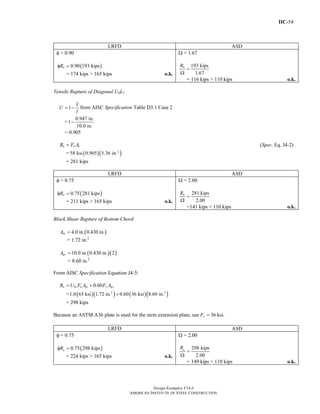


= 19.4 in.
Try a-in.-thick plate
Ag = a in.(19.4 in.)
= 7.28 in.2
Tensile Yielding of Gusset Plate
Return to Table of Contents](https://image.slidesharecdn.com/steel-construction-manual-design-examples-v14-0-pdf-151204051221-lva1-app6892/85/Steel-Construction-Manual-Design-examples-658-320.jpg)
![IIC-72
Design Examples V14.0
AMERICAN INSTITUTE OF STEEL CONSTRUCTION
From AISC Specification Equation J4-1:
LRFD ASD
φ = 0.90
φRn = φFyAg
= 0.90(36 ksi)(7.28 in.2
)(2)
= 472 kips > 316 kips o.k.
Ω = 1.67
=
Ω Ω
y gn F AR
=
( )( )2
36 ksi 7.28 in. 2
1.67
= 314 kips > 226 kips o.k.
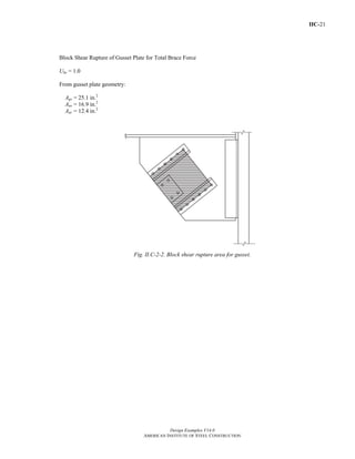
Block Shear Rupture of Gusset Plate
Tension stress is uniform, therefore, Ubs = 1.0. Assume a 2-in. edge distance on the diagonal gusset plate
connection.
tp = a in.
Agv = a in.{2 lines[(4 spaces)(3 in.) + 2 in.]}
= 10.5 in.2
Anv = 10.5 in.2
− (a in.)(2 lines)(4.5 bolts)(1z in. + z in.)
= 6.70 in.2
Ant = a in.[5.50 in. - (1z in. + z in)]
= 1.64 in.2
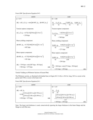
From AISC Specification Equation J4-5:
LRFD ASD
φ = 0.75
φRn = φUbsFuAnt + min(φ0.60FyAgv, φ0.6FuAnv)
Tension rupture component:
φUbsFuAnt = 0.75(1.0)(58 ksi)(1.64 in.2
)
= 71.3 kips
Shear yielding component:
φ0.60FyAgv = 0.75(0.6)(36 ksi)(10.5 in.2
)
= 170 kips
Shear rupture component:
φ0.6FuAnv = 0.75(0.6)(58 ksi)(6.70 in.2
)
= 175 kips
Ω = 2.00
0.60 0.60
min ,
Ω Ω Ω Ω
⎛ ⎞⎟⎜= + ⎟⎜ ⎟⎟⎜⎝ ⎠
y gvn bs u nt u nvF AR U F A F A
Tension rupture component:
( )( )2
1.0 58 ksi 1.64 in.
2.00
47.6 kips
Ω
=
=
bs u ntU F A
Shear yielding component:
( )( )2
0.6 36 ksi 10.5 in.0.6
2.00
113 kips
Ω
=
=
y gvF A
Shear rupture component:
( )( )2
0.6 58 ksi 6.70 in.0.6
2.00
117 kips
u nvF A
Ω
=
=
Return to Table of Contents](https://image.slidesharecdn.com/steel-construction-manual-design-examples-v14-0-pdf-151204051221-lva1-app6892/85/Steel-Construction-Manual-Design-examples-659-320.jpg)


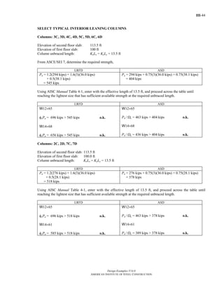
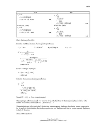
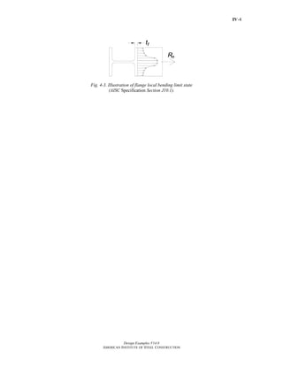
![III-8
Design Examples V14.0
AMERICAN INSTITUTE OF STEEL CONSTRUCTION
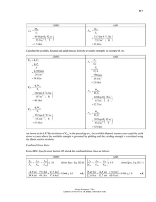
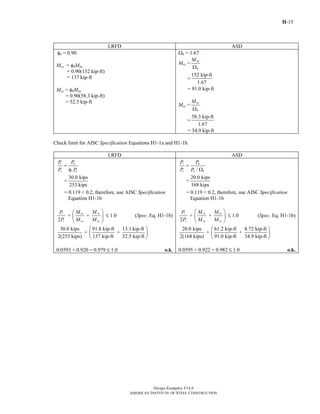
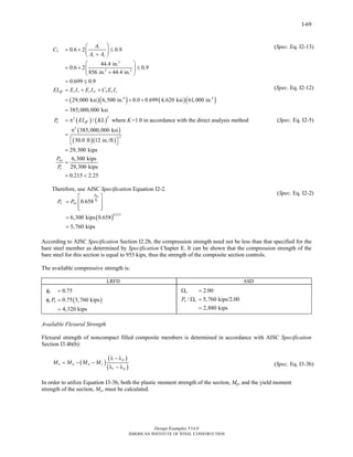
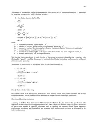
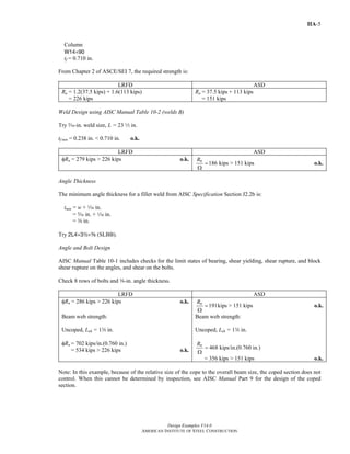
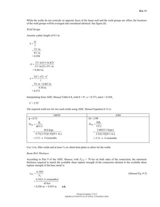
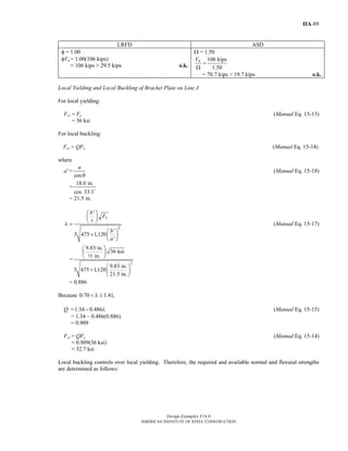
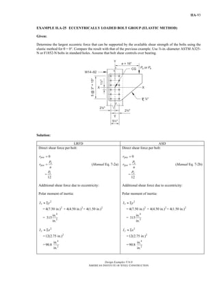
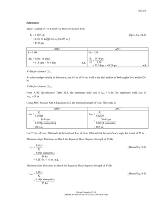
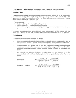
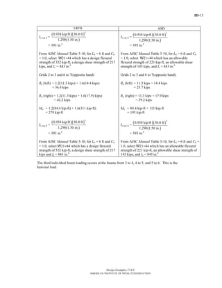
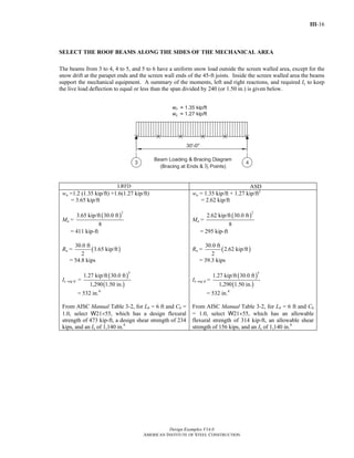
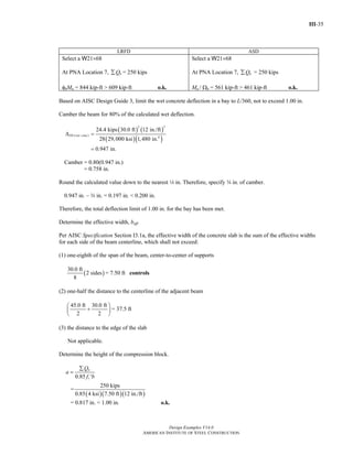
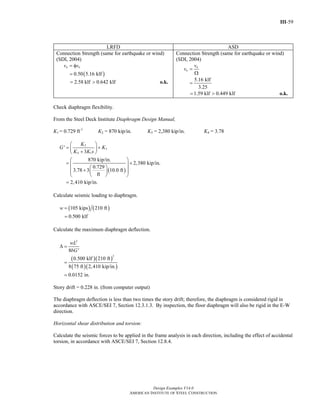
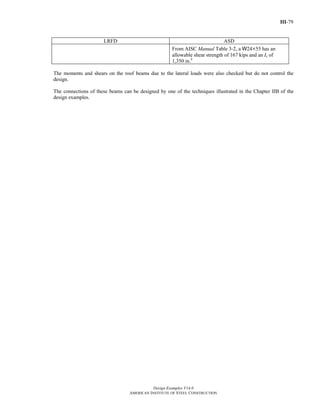
SELECT ROOF BEAMS
Calculate loads and select beams in the mechanical area.
For the beams in the mechanical area, the mechanical units could weigh as much as 60 psf. Use 40 psf additional
dead load, which will account for the mechanical units and the screen wall around the mechanical area. Use 15
psf additional snow load, which will account for any snow drift which could occur in the mechanical area. The
beams in the mechanical area are spaced at 6 ft on center.
Per AISC Design Guide 3 (West et al., 2003), calculate the minimum Ix to limit deflection to l/360 = 1.00 in.
because a plaster ceiling will be used in the lobby area. Use 40 psf as an estimate of the snow load, including
some drifting that could occur in this area, for deflection calculations.
Note: The beams and supporting girders in this area should be rechecked when the final weights and locations for
the mechanical units have been determined.
Ireq (Live Load) =
( )
( )
4
0.240 kip/ft 30.0 ft
1,290 1.00 in.
= 151 in.4
Calculate the required strengths from Chapter 2 of ASCE/SEI 7 and select the beams in the mechanical area.
LRFD ASD
wu = 6.00 ft[1.2 (0.020 kip/ft2
+ 0.040 kip/ft2
)
+1.6(0.025 kip/ft2
+ 0.015 kip/ft2
)]
= 0.816 kip/ft
Ru = ( )
30.0 ft
0.816 kip/ft
2
= 12.2 kips
Mu =
( )
2
0.816 kip/ft 30.0 ft
8
= 91.8 kip-ft
Assuming the beam has full lateral support, use
Manual Table 3-2, select an ASTM A992 W14×22,
which has a design flexural strength of 125 kip-ft, a
design shear strength of 94.5 kips, and an Ix of 199
in.4
wa = 6.00 ft[0.020 kip/ft2
+ 0.040 kip/ft2
+ 0.025 kip/ft2
+ 0.015 kip/ft2
]
= 0.600 kip/ft
Ra = ( )
30.0 ft
0.600 kip/ft
2
= 9.00 kips
Ma =
( )
2
0.600 kip/ft 30.0 ft
8
= 67.5 kip-ft
Assuming the beam has full lateral support, use
Manual Table 3-2, select an ASTM A992 W14×22,
which has an allowable flexural strength of 82.8 kip-
ft, an allowable shear strength of 63.0 kips and
an Ix of 199 in.4
Return to Table of Contents](https://image.slidesharecdn.com/steel-construction-manual-design-examples-v14-0-pdf-151204051221-lva1-app6892/85/Steel-Construction-Manual-Design-examples-693-320.jpg)


This document provides design examples for structural steel design using the 2010 AISC Specification for Structural Steel Buildings and the 14th Edition AISC Steel Construction Manual. The examples cover a range of structural members and connections, including tension members, compression members, flexural members, members under combined forces, composite members, and hollow structural section connections. The examples demonstrate both Load and Resistance Factor Design and Allowable Stress Design approaches.


