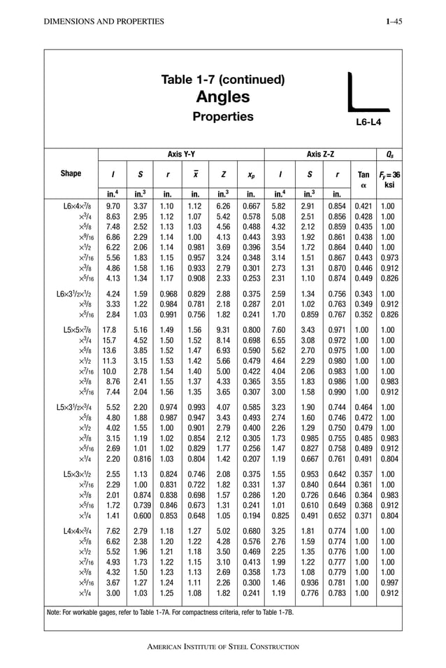
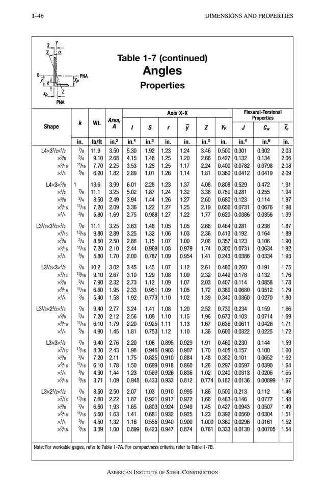
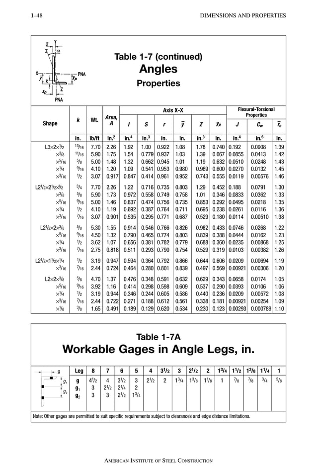
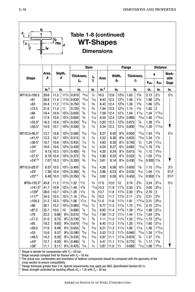
This document provides a summary of the chapters included in the 14th edition of the Steel Construction Manual published by the American Institute of Steel Construction. The manual covers topics related to the design of structural steel buildings and bridges including dimensions and properties of sections, design of flexural, compression, tension and combined force members, and design of connections including bolted, welded and bearing type connections. It also includes specifications, codes and supplementary reference materials.


![x
AMERICAN INSTITUTE OF STEEL CONSTRUCTION
SCOPE
The specification requirements and other design recommendations and considerations sum-
marized in this Manual apply in general to the design and construction of steel buildings and
other structures.
The design of seismic force resisting systems also must meet the requirements in the
AISC Seismic Provisions for Structural Steel Buildings, except in the following cases for
which use of the AISC Seismic Provisions is not required:
• Buildings and other structures in seismic design category (SDC) A
• Buildings and other structures in SDC B or C with R = 3 systems [steel systems not
specifically detailed for seismic resistance per ASCE/SEI 7 Table 12.2-1 (ASCE, 2010)]
• Nonbuilding structures similar to buildings with R = 11
/2 braced-frame systems or
R = 1 moment-frame systems; see ASCE/SEI 7 Table 15.4-1
• Nonbuilding structures not similar to buildings (see ASCE/SEI 7 Table 15.4-2), which
are designed to meet the requirements in other standards entirely
Conversely, use of the AISC Seismic Provisions is required in the following cases:
• Buildings and other structures in SDC B or C when one of the exemptions for steel
seismic force resisting systems above does not apply
• Buildings and other structures in SDC B or C that use composite seismic force resist-
ing systems (those containing composite steel-and-concrete members and those
composed of steel members in combination with reinforced concrete members)
• Buildings in SDC D, E or F
• Nonbuilding structures in SDC D, E or F when the exemption above does not apply
The AISC Seismic Design Manual provides guidance on the use of the AISC Seismic
Provisions.
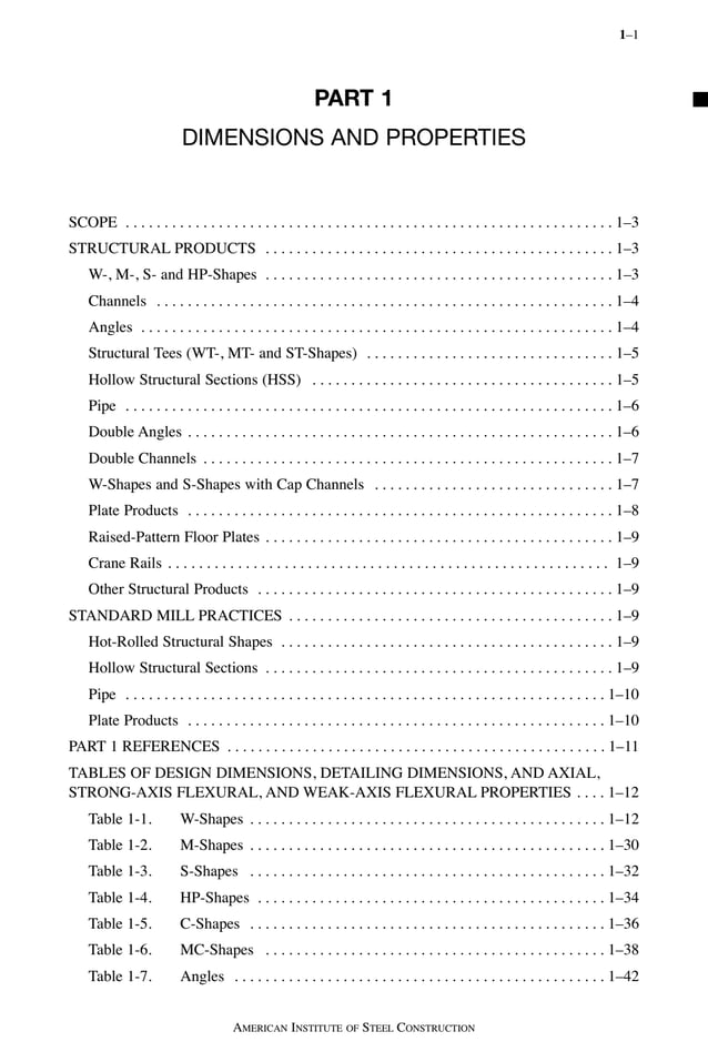
The Manual consists of seventeen parts addressing various topics related to steel build-
ing design and construction. Part 1 provides the dimensions and properties for structural
products commonly used. For proper material specifications for these products, as well as
general specification requirements and other design considerations, see Part 2. For the
design of members, see Parts 3 through 6. For the design of connections, see Parts 7 through
15. For AISC Specifications and Codes, see Part 16. For other miscellaneous information,
see Part 17.
REFERENCE
ASCE (2010), Minimum Design Loads for Buildings and Other Structures, ASCE/SEI 7-10,
American Society of Civil Engineers, Reston, VA.
AISC_Prelims:14th Ed. 1/20/11 7:23 AM Page x](https://image.slidesharecdn.com/steelconstructionmanualfourteenthedi-240120180500-549893fc/85/Steel_construction_manual_fourteenth_edi-pdf-11-638.jpg)


![Permissible Cross-Sectional Variations
Over Under Over Under
To 12, incl. 1/8
1/8
1/4
3/16
1/4
3/16
1/4
Over 12 1/8
1/8
1/4
3/16
5/16
3/16
1/4
Permissible Variations in Length
Variations from Specified Length for Lengths Given, in.
Nominal Depthb
, in. 30 ft and Under Over 30 ft
Over Under Over Under
Beams 24 in. and under 3
/8
3
/8
3/8 plus 1/16 for each additional 3
/8
5 ft or fraction thereof
Beams over 24 in. 1
/2
1
/2
1/2 plus 1/16 for each additional 5 ft or 1
/2
All columns fraction thereof
Mill Straightness Tolerancesc
Sizes Length
Permissible Variation in Straightness, in.
Camber Sweep
Flange width equal to
or greater than 6 in.
All
Flange width less
than 6 in.
All
Certain sections with a
flange width approx. 45 ft and under
equal to depth &
specified on order Over 45 ft
as columnsd
Other Permissible Rolling Variations
Area and Weight −2.5 to +3.0% from the theoretical cross-sectional area or the specified nominal weighte
Ends Out of Square 1/64 in., per in. of depth, or of flange width if it is greater than the depth
a Variation of 5/16 in. max. for sections over 426 lb/ft.
b For shapes specified in the order for use as bearing piles, the permitted variations are plus 5 in. and minus 0 in.
c The tolerances herein are taken from ASTM A6 and apply to the straightness of members received from the rolling mill, measured
as illustrated in Figure 1-1.
d Applies only to W8×31and heavier, W10×49 and heavier, W12×65 and heavier, W14×90 and heavier, HP8×36, HP10×57, HP12×74
and heavier, and HP14×102 and heavier. If other sections are specified on the order as columns, the tolerance will be subject to
negotiation with the manufacturer.
e For shapes with a nominal weight ≥ 100 lb/ft, the permitted variation is ±2.5% from the theoretical or specified amount.
DIMENSIONS AND PROPERTIES 1–119
AMERICAN INSTITUTE OF STEEL CONSTRUCTION
Table 1-22
ASTM A6 Tolerances for W-Shapes
and HP-Shapes
Nominal
Depth, in.
A
Depth at Web Centerline, in.
B
Flange Width, in.
T + T′
Flanges Out
of Square,
Max. in.
Ea
Web Off
Center, in.
C, Max.
Depth at any
Cross-Section
over Theoretical
Depth, in.
3/8 in. +
[1/8 in. ×
]
1/8 in. × with 3/8 in. max.
1/8 in. ×
(total length, ft)
10
(total length, ft)
10
(total length, ft – 45)
10
1/8 in. ×
(total length, ft)
10
1/8 in. ×
(total length, ft)
5
AISC_PART 01B:14th Ed._ 1/20/11 7:34 AM Page 119](https://image.slidesharecdn.com/steelconstructionmanualfourteenthedi-240120180500-549893fc/85/Steel_construction_manual_fourteenth_edi-pdf-130-638.jpg)


![DESIGN TABLE DISCUSSION 3–9
AMERICAN INSTITUTE OF STEEL CONSTRUCTION
DESIGN TABLE DISCUSSION
Flexural Design Tables
Table 3-1. Values of Cb for Simply Supported Beams
Values of the LTB modification factor, Cb, are given for various loading conditions on sim-
ple-span beams in Table 3-1.
W-Shape Selection Tables
Table 3-2. W-Shapes—Selection by Zx
W-shapes are sorted in descending order by strong-axis flexural strength and then grouped
in ascending order by weight with the lightest W-shape in each range in bold. Strong-axis
available strengths in flexure and shear are given for W-shapes with Fy = 50 ksi (ASTM
A992). Cb is taken as unity.
For compact W-shapes, when Lb ≤ Lp, the strong-axis available flexural strength, φbMpx
or Mpx/Ωb, can be determined using the tabulated strength values. When Lp < Lb ≤ Lr,
linearly interpolate between the available strength at Lp and the available strength at Lr
as follows:
Fig. 3-2. Loading constants for use in determining simple beam deflections.
LRFD ASD
φbMn = Cb [φbMpx ⫺ φbBF(Lb − Lp)]
≤ φbMpx (3-4a)
M
C
M BF
L L
M
n
b
px
b
b p
px
= – ( )
b b
b
Ω Ω Ω
Ω
–
⎡
⎣
⎢
⎤
⎦
⎥
≤
(3-4b)
AISC_Part 3A:14th Ed. 2/24/11 8:39 AM Page 9](https://image.slidesharecdn.com/steelconstructionmanualfourteenthedi-240120180500-549893fc/85/Steel_construction_manual_fourteenth_edi-pdf-200-638.jpg)