This document discusses centralized substation protection and control (CPC) systems. It provides a brief history of power system protection and control and how CPC has evolved. It describes the impact of changing grid topology that is driving more advanced protection and control solutions. It then examines CPC architectures within a substation and the technologies that enable CPC like merging units and communication networks. It also discusses reliability, cost, testing and advanced applications of CPC. Finally, it reviews demonstration projects of CPC and emerging applications like dynamic state estimation based protection and wide area protection.


![2015 – December WG K15 Report - Centralized Substation Protection and Control 2
2. BRIEF HISTORY OF POWER SYSTEM PROTECTION AND CONTROL
The history of protection goes back to the end of the nineteenth century. The first protection device
invented and used was the fuse. Fuses were originally introduced in the North American and European
markets almost simultaneously in mid-1880 [1]. The objective was to protect lamps because, at that time,
the cost of a lamp was approximately equal to two weeks’ gross earnings of an average worker. Only
about three years after their introduction in the market, fuses were applied to protect circuits.
The first protection relay was developed in the early 1900s and the first installation was made in 1905
[2].The first Supervisory Control and Data Acquisition (SCADA) systems, although not called SCADA at
the time, likely developed in the power industry with remote sensing of operation status in Chicago
around 1912. Westinghouse Electric Corporation prepared a System Requirements Specification for a
“Substation Control and Protection System” for EPRI Research Project RP-1359-1 in April 1980 [3] and
developed the WESPAC system based on this specification in 1980s. The 'Integrated Protection System
for Rural Substations' or ‘Sistema Integrado de Protección para Subestaciones Rurales’ (SIPSUR) was
developed by GE and the North West Utility in Spain, Union Electrica Fenosa in 1990 [4]. Ontario Hydro
developed the Integrated Protection and Control System (IPACS), with the first system installed in 1992.
A more recent example is the centralized protection and control system for the island of Gotland installed
in 2000 by Vattenfalls Eldistribution of Sweden [5].
2.1 Protection (Relaying)
The evolution can be divided into three main stages; the first stage was the era of electromechanical
relays, which started over 100 years ago. The next era was characterized by static or solid state relays,
which were introduced in the 1960s. The present era with microprocessor based relays started in the
beginning of the 1980s, where microprocessor performed the logics, but the filtering was analog.
Although earlier prototype systems had been implemented, the first commercially available fully
numerical relay was introduced in 1984.
In the history of electrical protection, the basic function of protection has not changed: to properly detect
a disturbance in the system and to clear the faulted area. Different technologies have been applied to
change the form of a protective relay as most of the relaying fundamentals are inherited from previous
technologies [6, 7, 8, 9].
The original protection relay, the electromechanical relay, still has a large installed base. It is not
uncommon to hear of electromechanical relays that have been in service for 50-60 years. In the early
1960s, advances in large-scale integration technology enabled the use of electronics in relays. Before
solid state relays were largely accepted as an industry standard, research in applying computer technology
to protective relaying had already begun by the late 1960s. Initial experiments were performed using
computer-based systems. It was suggested in mid-1960’s that computers could be used to protect
components of power systems [10]. During the 1970s, great advances were made in hardware technology
as well as in software techniques. These advances led to the first commercially available microprocessor-
based relay in 1984. Continuous advances in electronics combined with extensive research in
microprocessor-based systems reached a point where few applications could not be covered by a
numerical/digital relay by the late 1980s.](https://image.slidesharecdn.com/ieee1-160309075548/85/slide-6-320.jpg)

![2015 – December WG K15 Report - Centralized Substation Protection and Control 4
2.2 Control
While protection is associated with protecting the power system from abnormal operation, the control
system is primarily concerned with supporting the operation of the substation equipment. Because the
control system provides access to changing the state of substation equipment, it is leveraged by protection
devices to remediate any abnormal operating conditions detected by the protection system. While the
control system typically acts slowly, perhaps on the scale of seconds, the protection system typically acts
at a much higher speed, i.e. ¼ -1cycle (~ 4 to 16 ms for 60 Hz).
There are two basic types of control operation, manual and automatic control. Manual control is
performed by personnel using control switches to change the operating state of electrical equipment for
some reason, such as equipment maintenance, load transfer, change transformer tap position, override
automatic control, etc. Automatic control is used when the control system performs some task
automatically, without human intervention, by measuring the parameter being controlled and all of the
inputs and outputs that change the measured parameter. Automatic controls are most commonly found in
transformer automatic load tap changers and capacitor bank controls.
Both automatic and manual control can be performed locally at the equipment level, at a control house,
remotely from a centralized location such as a control center, or any combination of the three. Local
control is typically performed at the control house or at the equipment, where all control circuits are
actually hardwired from the switches to the equipment. Remote manual control is typically performed
from a location considered remote, or far away, from the equipment’s location, where today there is no
hardwired connection all the way from the operator in the control center to the equipment being operated.
Automated control can also take place locally at the substation (in the control house or at equipment) or
remotely at the control center. This centralized automatic control is actually one approach to distribution
automation, where automatic control is maximizing the performance of the distribution grid through
reactive power and circuit configuration optimization using real-time load flow analysis based upon data
being automatically reported from equipment on the distribution circuits and in distribution substations.
Just as the application of advanced control technology to distribution system is called distribution
automation, similarly its application in substations is typically called substation automation. Both are
somewhat ironic because the amount of actual automatic control being performed, ignoring protection as
a form of automatic control that it is, may actually be quite small. Interestingly, the amount of automated
data collection is quite high, which reflects the roots of substation automation in the first forms of
SCADA technology.
The first SCADA systems, although not called SCADA at the time, likely started in the power industry
with remote sensing of operation status in Chicago around 1912. At that time, telephone lines were used
to transmit data from a number of electric power plants to a central office. It is likely this “supervisory”
control was done to avoid having personnel stationed at the remote site to continuously monitor the
equipment. By 1937, supervisory control, supervisory indication, and telemetering were defined in IEEE
C37.2. By 1955, the term telemetering was officially defined by the AIEE as measuring with the aid of
intermediate means which permit the measurement to be interpreted at a distance from the primary
detector [11]. By the 1960s, the expression “Supervisory Control and Data Acquisition” was being used
by the Bonneville Power Administration in planning studies [12]. In 1984, ISA-RP60.6 defines the
SCADA acronym. In 1987, IEEE C37.1 contained the term “scada” for the first time, but interestingly it](https://image.slidesharecdn.com/ieee1-160309075548/85/slide-8-320.jpg)

![2015 – December WG K15 Report - Centralized Substation Protection and Control 6
Accordingly, electric utilities typically buy versions of telecommunications industry products with
modifications made for this industry, such as surge withstand capability, wide temperature variations,
abnormal vibrations, and immunity to electromagnetic, electrostatic and radio interference. This is the
case for the digital communications systems applied in the typical environments found in power system
substations.
In the new era of protection and control, it is very important that protection and control engineers
understand digital telecommunication system architecture [13, 14]. However, as mentioned before, the
environmental requirements for the application of digital communications for substation automation are
more stringent to ensure an acceptable and reliable performance.
2.4 Centralized Protection and Control
There is no formal centralized protection and control (CPC) definition in the IEEE based upon the
working group’s survey of IEEE publications. This report defines a CPC system as a system comprised of
a high-performance computing platform capable of providing protection, control, monitoring,
communication and asset management functions by collecting the data those functions require using high-
speed, time synchronized measurements within a substation.
The concept of CPC dates back almost to the beginning of the wide adoption of computers for business,
starting with a first proposal published in 1969 [15], and a first installation as a field proof of concept in
1971 [16, 17]. The early experimental systems focused on computer relaying in general, and were limited
by the technology available at the time. Projects in the late 1980s and early 1990s began to experiment
with centralized protection and control specifically. This section is an overview of some of the projects
and systems that have been installed.
2.4.1 Westinghouse Electric Corporation Project - USA
Westinghouse Electric Corporation prepared a System Requirements Specification for a “Substation
Control and Protection System” for EPRI Research Project RP-1359-1 in April 1980 [3]. This
specification is considered to be one of the earlier attempts to provide protection and control in an
integrated system. The report includes Line, Transformer, Bus, Shunt Reactor, Out-of-step and Breaker
Failure protections. The specification also includes control features such as local control of voltage, VAR
flow, load shedding and automated switching sequence. Monitoring features including sequence of events
records and oscillography are also considered in the specification. System restoration aid such as fault
location estimation is also included in the specification. Revenue metering and SCADA interface were
also considered. Based on this specification, WESPAC system shown in Figure 2, was developed and
deployed in several substations starting in early 1980s [18,19]. American Electric Power (AEP)
developed an Integrated Modular Protection and Control system (IMPACS) during this period while
ASEA had developed a hybrid system in conjunction with the Swedish State Power Board [20].
2.4.2 SIPSUR – Spain
The SIPSUR system was developed by GE and the North West Utility in Spain, Union Electrica Fenosa
in 1990 [4]. SIPSUR was a project to integrate in a single hardware package a complete protection system
for a medium voltage (MV) distribution substation. The system comprised two incoming feeders, one](https://image.slidesharecdn.com/ieee1-160309075548/85/slide-10-320.jpg)
![2015 – December WG K15 Report - Centralized Substation Protection and Control 7
transformer and five distribution feeders. The specialty of this system was the concept of “Back-up CPU ”
as shown in Figure 3.
Figure 2. WESPAC integrated system [21].
Figure 3. Back-up CPU concept in SIPUR – Spain [4].](https://image.slidesharecdn.com/ieee1-160309075548/85/slide-11-320.jpg)
![2015 – December WG K15 Report - Centralized Substation Protection and Control 8
2.4.3 Ontario Hydro IPACS System – Canada
Ontario Hydro developed the IPACS (Integrated Protection and Control System), shown in Figure 4, with
the first system installed in 1992. IPACS was a computer system designed in one box panel by Ontario
Hydro to do all the protection, control, monitoring, and recording for a Dual Element Spot Network
(DESN) station. A DESN station is a transformer station that steps voltage down from transmission to
distribution levels. Every element (transformer, bus, etc.) are duplicated and configured so that individual
elements may be taken out of service without interrupting supply to loads. Ontario Hydro (now Hydro
One) has about 300 DESN stations, and IPACS was developed to be a cost effective method to refurbish
these stations. 56 IPACS systems were built and installed before the project was abandoned in 1998.
IPACS was an all-in-one solution for DESN substations, and included protection for feeders, capacitors,
buses, transformers, etc.; full metering including tapchanger position and DC battery voltage; SCADA
RTU functionality for up to 2 masters; local control and HMI; and other functions such as voltage
regulation, reclosing, capacitor auto switching, underfrequency load shedding, digital fault recording,
sequence of events recording, power quality monitoring, and breaker wear monitoring.
The IPACS system uses a single CPU to implement all functions. Reliability of protection and control is
provided by having a second IPACS system, or by other types of redundancy. This can be a completely
identical IPACS system, or using a full function conventional protection/metering/SCADA backup, or
limited function conventional backup.
2.4.4 Vattenfalls Project - Sweden
Vattenfalls Eldistribution developed a centralized protection and control system, shown in Figure 5, for
the island of Gotland in 2000 [5]. The system was developed in collaboration with ABB, with all
protection and control algorithms operating on a standard industrial computer. The system was developed
starting with technology used for protection and control of HVDC substations, adding AC protection
algorithms to the existing control system.
Each protection and control system uses an industrial computer and I/O devices connected to the primary
processor. Each computer connects up to 5 I/O racks, with processor cards for analog and digital inputs
and outputs. The I/O signals are connected to the computers via a separate cabinet with terminal blocks
for each computer. The operating system in the computers is a real time kernel in combination with
Embedded Windows operating system. System software and the application programs for the different
protection and control functions are run on top of this operating system. The first of these systems were
installed in 2000, with 5 different systems in service.
The concept behind developing this solution with standard computers is to support simplified handling of
installation and testing, and the future ability to add other novel station functionality, such as internal self-
control of the station. The system as designed by Vattenfalls has the ability to implement any protection
algorithm, from any vendor. New algorithms can be chosen, and rolled out to all installations
simultaneously, providing rapid, system-wide upgrades for protection and control.](https://image.slidesharecdn.com/ieee1-160309075548/85/slide-12-320.jpg)
![2015 – December WG K15 Report - Centralized Substation Protection and Control 9
Figure 4. Ontario Hydro IPACS System – Canada.
Figure 5. Gotland –Sweden, Centralized protection and control system by Vattenfalls Eldistribution [5].](https://image.slidesharecdn.com/ieee1-160309075548/85/slide-13-320.jpg)

![2015 – December WG K15 Report - Centralized Substation Protection and Control 11
3. IMPACT OF CHANGING GRID TOPOLOGY
Smart grid development is changing power system characteristics, at a time when utilities are also
focusing on improving customer service and resiliency of the grid. Wide Area Situation Awareness
(WASA) and System Integrity Protection Schemes (SIPS) are gaining more momentum for safe, reliable
and stable operation and control of a power grid. The power system changes are more apparent in
distribution systems due to the integration of renewable energy resources, energy storage and electric
vehicles [22]. The use of power electronics-based equipment for lighting, drives and distributed
generation sources are also impacting power quality as well as system operation and control [23].
Figure 7 illustrates the vastness and scale of the North American electric grid with respect to geographical
area with diverse natural calamity, public policies and varying power system patterns which are common
to other parts of the world. Figure 8 illustrates the evolution of a typical electric power system. The
evolving system introduces many new challenges in policies, operation, maintenance, protection and
control from inception to life-cycle support.
Figure 7. North American Electric Power Grid [22].](https://image.slidesharecdn.com/ieee1-160309075548/85/slide-15-320.jpg)
![2015 – December WG K15 Report - Centralized Substation Protection and Control 12
Figure 8. An evolving electric power system [22].
The development of microgrids provides new opportunities in managing the grid - contributions to
capacity, reliability/resiliency, and power quality improvement. The evolution of dynamic microgrid will
further alter system characteristics. One such scenario is described in Figure 9, which takes a holistic view
of a power system from the balancing authority (BA) to the customer loads at distribution level. In this
scenario, conventional substations are complemented by microgrids under the control of a DMS as in
Figure 9 (b). These microgrids can be dynamic and substations can be used as dynamic control centers of
these microgrids in some scenarios. This feature complements the dedicated control centers of some
microgrids and offers maximum flexibility from the operation perspective. There is also a possibility for
asynchronous connection of microgrids with the main AC grid using medium voltage and low voltage DC
links. Applications that typically run today and are expected to run in future at different layers of a power
grid are also identified in Figure 9 [24].
Future protection and control systems should adapt to the architecture of the power system shown in
Figure 9. Control of active and reactive power at the distribution level while maintaining the regulation
voltage profile and frequency across the network will offer opportunities for greater innovation for
network owners and managers – utilities, distribution agencies, state or governmental agencies, and
reliability coordinators. Greater integration of the control system with the network protection devices will
assist in addressing these challenges and reduce the overall ownership cost of a more reliable and robust
system protection and control. This integrated approach will also assist in managing assets with
performance and retrofit/replacement requirement information for maintaining system reliability [24].
The CPC will play a very important role by combining various protection and control functions required
for the evolving grid. One of the benefits of having a high-performance computing platform like CPC at
the substation is the possibility of bringing intelligence to the substation. The CPC can act as a node for
distributed control architecture.](https://image.slidesharecdn.com/ieee1-160309075548/85/slide-16-320.jpg)
![2015 – December WG K15 Report - Centralized Substation Protection and Control 13
CPC will also address the hardware replacement requirement and software upgrade of the protection and
control system due to various reasons as discussed in [25], while minimizing system downtime.
(a)
(b)
(c)
Figure 9. Possible architecture of a distribution system connected to a larger grid, (a) from transmission system to DMS,
(b) from DMS to primary and secondary substations and (c) from substations to customer loads [24].](https://image.slidesharecdn.com/ieee1-160309075548/85/slide-17-320.jpg)
![2015 – December WG K15 Report - Centralized Substation Protection and Control 14
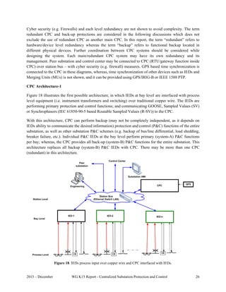
4. CENTRALIZED PROTECTION AND CONTROL WITHIN A SUBSTATION
The idea of IEDs sharing information opened up many possibilities with the clear potential of better
detection of fault conditions and improvements in protection security and dependability. These
possibilities can be implemented in a variety of architectures that may eventually include a central
computing platform in a substation to concentrate the information and perform protection using
centralized data. A centralized substation protection and control system is comprised of a high-
performance computing platform capable of providing protection, control, monitoring, communication
and asset management functions by collecting the data those functions require using high-speed, time
synchronized measurements. Figure 10, an extension of Figure 1 with the addition of Block 5, illustrates
the evolution of the protection, control, monitoring, and communication system leading to CPC [24].
Block 5 shows the transfer of sampled analog values from Intelligent Merging Units (IMUs) to CPCs as
well as GOOSE messages from CPCs to IMUs, and MMS messages transferred from IMUs to the CPC
using fiber optical communication. It is important to note that CPC technology should be able to co-exist
with all technologies in a substation, shown in Figure 10, to be able to attract retrofit application which is
often the case in a matured market.
Figure 10. Evolution of protection and control system leading to CPC, adapted from [24].
The report compares the traditional approach with CPC in section 4.1.The section 4.2 discusses the
existing technologies that are the backbone of various CPC architectures described in section 4.3 and
supported by advancement in communication technologies discussed in section 4.4. Reliability and cost
analysis of various CPC architectures are discussed in section 4.5 while testing of CPC systems are
covered in section 4.6. Section 4.7 discusses some of the advanced applications possible today with the
application of CPC.](https://image.slidesharecdn.com/ieee1-160309075548/85/slide-18-320.jpg)

![2015 – December WG K15 Report - Centralized Substation Protection and Control 16
One of the challenges of CPC approach is the aggregation of functionality which can reduce flexibility
for operation and maintenance of the equipment based on present practices as discussed in [26]. The
implementation of CPC approach will require a paradigm shift in the way we design, manufacture, install,
test, operate and maintain a protection and control system.
4.2 Existing Technologies Supporting CPC
Sensors are the front-end interface of CPC with the process, the power system. Recent advancements in
sensor technology make a CPC solution more attractive with the use of appropriate merging units.
Advancement in low-cost high-performance computing platforms makes them very attractive for the
application of CPCs. Standardized high reliability communication technology can help the
implementation of CPC architecture which will be driven by many factors: reduction in Capital
Expenditure (CapEx) including the wiring, Operation Expenditure (OpEx) including easy replacement of
hardware at the end-of-useful life [25] and seamless upgrade of firmware without any downtime to name
a few.
4.2.1 Optical Current and Voltage Sensors
Modern developments in fiber-optics technology and advancements in the associated electronic devices
have resulted in the development of non-conventional instrument transformers. One of the non-
conventional current transformer designs takes advantage of the Faraday Effect [27]. The basic approach
is that two linearly polarized beams are generated and are applied to a fiber optic that takes them to the
conductor level. The linearly polarized beams are converted to circular polarized beams, one to a left
circular polarization beam and the other to a right polarized beam. The fiber optic takes the circular
polarized beams around the conductor several times. As the beams travel through the magnetic field
produced by the current, one of the beams is accelerated and other is decelerated; the acceleration and
deceleration depend on the intensity of the magnetic field. The circular polarized beams are converted
back to linear polarized beams and are sent back to the sensing equipment at the ground level. The
change of phase between the beams are measured and then translated to the level of current in the
conductor.
One of the non-conventional electro-optic voltage transformer uses the Pockels cells. The basic principle
is that when a circular polarized beam passes through the cell, the polarization changes to elliptical
polarization. The change of polarization depends on the intensity of the electric field in which the
Pockels cell is placed.
4.2.2 Rogowski Coils as Current Sensor
Rogowski coils operate on the same magnetic-field principles as conventional iron-core current
transformers (CTs). The main difference between Rogowski coils and CTs is that in the Rogowski coil-
based solutions secondary equipment measures output voltages that are scaled time derivative di(t)/dt of
the primary current, while in the CT-based solutions, secondary equipment measures secondary currents
that are proportional to the primary current. The phase angle between the secondary voltage and primary
current is 90°. The reason why the secondary voltage is measured is because Rogowski coils are wound
using air-core material (relative permeability is equal one, µr = 1), the result being that the mutual
coupling between the primary conductor and the secondary winding is much smaller than in CTs. The
Rogowski coil output voltage is small (mV range during normal operation and several volts during](https://image.slidesharecdn.com/ieee1-160309075548/85/slide-20-320.jpg)
![2015 – December WG K15 Report - Centralized Substation Protection and Control 17
faults), so they cannot drive current through low-resistance burden like CTs are able to drive. Rogowski
coils can provide input signals for microprocessor-based devices that possess a high input resistance. The
Rogowski coil low-output signal is safer for people and secondary equipment, even when high currents
and voltages exist on the primary side. An open circuit or short-circuit in the signal cable will cause no
hazards or damage. Signal processing is required to extract the power frequency signal for phasor-based
protective devices and microprocessor-based equipment must be designed to accept these types of signals.
An important advantage over CTs is the Rogowski coil linear performance characteristic since the air-
core material cannot saturate.
Rogowski coils may achieve high accuracy (up to 0.1%). The same sensor can be used for both protection
and metering [28, 29]. Rogowski coils are classified as low-power current sensors and requirements are
specified by Standards [30, 31, 32]. IEC 61869-10 standard, “Specific requirements for low-power
passive current transformers,” is under development. IEEE Std. C37.235™-2007 [33] provides
guidelines for the application of Rogowski coils used for protective relaying purposes.
4.2.3 Merging Unit
The development of centralized substation protection and control systems is possible today based on the
developments of the object models and interfaces defined in the IEC 61850 standard. A function in an
IEC 61850 based protection and control system can be local to a specific primary device (distribution
feeder, transformer, etc.) or distributed and based on communications between two or more devices over
the substation local area network.
IEC 61850 defines several ways for data exchange between IEDs that can be used for different forms of
distributed protection and other applications. They introduce a new concept that requires a different
approach and technology in order to define the individual components of the system, as well as the overall
distributed applications. IEC 61850 defines several different interfaces that can be used for various
substation applications. They may use dedicated or shared physical connections - the communications
links between the physical devices. The allocation of functions between different physical devices defines
the requirements for the physical interfaces, and in some cases may be implemented into more than one
physical LANs. The functions in the substation can be distributed between IEDs on the same, or on
different levels of the substation functional hierarchy – Station, Bay or Process. They can also be
implemented in a central substation computer.
These levels and the logical interfaces are shown by the logical interpretation of Figure 11.](https://image.slidesharecdn.com/ieee1-160309075548/85/slide-21-320.jpg)
![2015 – December WG K15 Report - Centralized Substation Protection and Control 18
Figure 11. Logical interfaces in IEC 61850.
The logical interfaces (IFs) of specific interest to protection applications shown above are defined [34] as:
IF4: CT and VT instantaneous data exchange (especially samples) between process and bay level
IF8: direct data exchange between the bays especially for fast functions like interlocking
The first one is used typically for the so called process bus applications, while the second defines the
substation bus communications.
A significant improvement in functionality and reduction of the cost of centralized substation protection
and control systems can be achieved based on the IEC 61850 based communications as described below.
Non-conventional instrument transformers with digital interface based on IEC 61850-9-2 [35] (Process
Bus) result in further improvements and can help eliminate some of the issues related to the conflicting
requirements of protection and metering IEDs.
The interface of the instrument transformers (both conventional and non-conventional) with different
types of substation protection, control, monitoring and recording equipment is through a device called
Merging Unit. This is defined in IEC 61850-9-1 as:
“Merging unit: interface unit that accepts multiple analogue CT/VT and binary inputs and produces
multiple time synchronized serial unidirectional multi-drop digital point to point outputs to provide data
communication via the logical interfaces 4 and 5”.
Existing Merging Units have the following functionalities:](https://image.slidesharecdn.com/ieee1-160309075548/85/slide-22-320.jpg)

![2015 – December WG K15 Report - Centralized Substation Protection and Control 20
4.2.4 Remote I/O and Process Interface Unit/Device
The remote I/O module (RIO) is intended to be the status and control interface for primary system
equipment such as circuit breakers, transformers, and isolators. RIOs under IEC 61850 may support only
GOOSE publish and subscribe communications, or may also support MMS client and server
communications.
The process interface unit/device (PIU/PID) combines a MU and a RIO into one device. The PIU/PID
can publish analog values and equipment status, and accept control commands for equipment
operation. From an installation standpoint, a PIU/PID can make more sense in many applications than
separate MUs and RIOs.
4.2.5 Intelligent Merging Unit
The intelligent merging unit (IMU), shown in Figure 10, adds RMS-based (simple to derive from sampled
values) overcurrent and overvoltage back-up protection functions in a PIU/PID to prevent damage to the
related primary equipment in the event of total communication failure between the IMU and CPC during
abnormal system conditions. This type of device is not yet available and it is expected to evolve with MU
and PIU/PID technology irrespective of CPC application.
4.2.6 High-Performance Computing Platform
The optical isolation between IMUs and the CPC, shown in Figure 10, enables off-the-shelf hardware use
for the CPC, which is very important for the deployment of the CPC. Most protection functions from
distributed IEDs within a substation are integrated into the CPC. Advancement in low-cost, high-
performance rugged computing platforms combined with the availability of standardized high-reliability
communication technologies make them very attractive for the CPC applications. A high-performance
computing platform based on server technologies for the CPC is shown in Figure 13 [24]. Time
synchronization between the CPC (servers in Figure 13) and IMUs is achieved using precision time
protocol (PTP) as per IEEE 1588-2008 (v2).
One of the main advantages of using a high-performance computing platform like servers is the efficient
management of end-of-life of hardware. Server technology is used by many industries across various
technology areas, so the wide availability of next generation of hardware would appear to be guaranteed
at a competitive price and users would have much wider choices for hardware supplier.
Use of off-the-shelf hardware for CPC like that used in energy management system will also be very
helpful to the IED suppliers. They can focus on developing specialized CPC application software that can
run on commercially available standard platforms. In addition, availability of standardized high-
performance computing platform opens the opportunity for development of complex protection and
control algorithms necessary for the future grid, to accommodate the changing power system
characteristics.](https://image.slidesharecdn.com/ieee1-160309075548/85/slide-24-320.jpg)
![2015 – December WG K15 Report - Centralized Substation Protection and Control 21
Figure 13. Server based CPC system [24].
CPC has to meet applicable standards for substation environment, such as IEEE 1613 and IEC 61850-
3:2013. Electrical isolation of the CPC via optical fiber cables for communications is beneficial in this
respect. However, a CPC’s power supply and other peripheral connections have to withstand the
substation environment.
4.2.7 Advancements in Communication Technology
Substation protection and control systems require reliable, secure communications infrastructure which is
also true for CPC architectures. These are mission-critical systems that have to process real time events
on a millisecond level for protections and control operations. Many of these modern communications
networks rely on packet based Ethernet messaging. Applications using digital messages to exchange
binary protection signals require that networks never drop more than four consecutive packets or take
longer than 15 milliseconds to reconfigure. Applications using digital messages to exchange analog
protection signals require that networks never drop more than three consecutive packets to bump-less
calculation of mission critical algorithms.
There are a number of existing standard redundant protocols used in substation Ethernet LANs that
provide network fault detection, isolation, and restoration for resiliency including IEC 62439-1 Spanning
Tree Algorithm (STA) using Spanning Tree Protocol (STP), Rapid Spanning Tree Protocol (RSTP), and
Media Redundancy Protocol (MRP) to name a few. Other emerging redundancy protocols without fault
detection but that help provide zero (0) second recovery time and zero-packet loss include IEC 62439-3
protocols called High-availability Seamless Redundancy (HSR) and Parallel Redundancy Protocol (PRP)
[36]. According to the IEC 61850 Ed 2, the applications using the process bus Sampled Value (SV) and
GOOSE messaging require bump-less calculations and low loss communication that can be achieved in
HSR/PRP networks. Other examples of future potential technologies/protocols are Time Sensitive
Networks (TSN) based on IEEE 802.1 series with Deterministic Ethernet (DE); Software Defined
Network (SDN) based on IEEE projects P1903 and 802.1CF; etc.](https://image.slidesharecdn.com/ieee1-160309075548/85/slide-25-320.jpg)
![2015 – December WG K15 Report - Centralized Substation Protection and Control 22
One of the main criteria for selecting CPC communication architecture is the level of redundancy, overall
cost (Capital Expenditures (CapEx), Operation Expenditures (OpEx)) and performance such as
switchover time, latency, bandwidth and processing power.
HSR/PRP networks provide:
Reliability in critical applications
Seamless switchover, zero-frame loss
Zero-Loss redundancy
o No single point of failure
o Zero-time recovery
o No packets loss (minimum latency)
Zero down time
o devices can be removed from network without traffic loss
Support for IEEE 1588 clock synchronization
The basic principle of HSR/PRP protocol is that the source node duplicates packets and sends them in
redundant directions - across the ring in case of HSR or to both LANs in case of PRP, as in Figure 14.
The first packet that reaches the destination will be accepted and the duplicate packet will be rejected.
Detailed description of the protocol can be found in [36].
Figure 14. Conceptual diagrams of PRP and HSR networks.
4.2.8 Advancements in Time Synchronization Technology
Time synchronization service is required for various existing and emerging protection and control
applications. Two types of time synchronization can be used: synchronization to a relative time and
synchronization to an absolute time. Synchronization to a relative time implies synchronization of two or
more devices, possibly in a centralized architecture, to a common time that can be different from the
absolute time.](https://image.slidesharecdn.com/ieee1-160309075548/85/slide-26-320.jpg)
![2015 – December WG K15 Report - Centralized Substation Protection and Control 23
Synchronization to an absolute time implies synchronization of two or more devices to a reference of the
absolute time, most commonly to a reference of Coordinated Universal Time (UTC). Synchronization to
UTC in turn is often achieved using clocks with Global Positioning System (GPS) receivers and time
distribution interfaces such as IRIG-B and Precision Time Protocol (PTP). Recently, the US government
discussed a proposal to use Enhanced Loran (eLoran) system as a backup to GPS for navigation and time
distribution services [37, 38].
Most communication-assisted protection and control systems also require time synchronization to relate
and align data from various locations. Communication and time synchronization architectures can be the
same, partially overlapping or completely different and independent. Various time synchronization
methods and technologies can be used as well. For relative time synchronization various proprietary
methods have been used. These are commonly based on exchanging messages with time information
between devices, and measuring propagation delay. These methods assume delay symmetry in transmit
and receive direction. Terms like “ping pong” or “echo”/ “echo timing” are used for these methods.
It should be noted that methods used for synchronization to an absolute time fulfill requirements for
synchronization to a local time as well. For synchronization to an absolute time, GPS has been commonly
used to acquire UTC time. To distribute time from GPS receiver to other devices in a substation, Inter-
range instrumentation group time codes, commonly known as IRIG time codes are often used [39]. This
method requires dedicated cabling, time code signals can be sent over copper coaxial cabling with BNC
connectors or over fiber optics that offers advantages of immunity to electromagnetic interferences.
Physically signals can be transferred as DC level shift or amplitude modulation at 1 kHz carrier. Other
time distribution methods include Network Time Protocol (NTP), Simple Network Time Protocol
(SNTP), DNP 3.0, etc. These methods, however, do not provide high time accuracy of 1 microsecond,
required for some protection and control applications.
IEEE 1588 Standard for a Precision Clock Synchronization Protocol for Networked Measurement and
Control Systems specifies Precision Time Protocol (PTP) for time distribution over Ethernet with sub
microsecond time accuracy. The second version of this standard published in 2008, specifies multiple
ways of achieving the above goal [40]. It introduced the concept of a profile, a subset of available
variants, that industries are required to generate to meet requirements of their applications.
IEEE C37.238-2011 Standard Profile for Use of IEEE 1588™ Precision Time Protocol in Power System
Applications specifies a PTP profile for power industry [41]. Using Ethernet-based synchronization
permits reduction in the number of GPS receivers required and eliminates the need for architecture and
cabling dedicated only to time synchronization, such as IRIG-B cabling. In addition to protocol details
such as Layer 2 communication, multicast messaging, IEEE C37.238-2011 also specifies performance
requirements. 1 microsecond time accuracy is expected at the input of the end device located 16
communication hops away from the time source, connected to GPS, shown in Figure 15.](https://image.slidesharecdn.com/ieee1-160309075548/85/slide-27-320.jpg)
![2015 – December WG K15 Report - Centralized Substation Protection and Control 24
Figure 15. Time synchronization performance requirements specified by IEEE C37.238-2011.
The ongoing IEEE C37.238-2011 revision project led to joint work with IEC TC57 WG10 which resulted
in generation of a common Level 1 profile – IEC PAS 61850-9-3: Precision time protocol profile for
power utility automation. Once it is approved, it will provide a single common base profile for the power
industry; benefiting users, implementers and the industry [42].
Various synchronization methods could be used in the same system simultaneously. Figure 16 provides
an example of time distribution architecture with the use of multiple time synchronization technologies.
Communication and time synchronization architectures can be the same, partially overlapping or
completely different and independent. Figure 17 provides an example of synchrophasor-based application
where communications and synchronization are different: GPS receivers are installed in each end device.
Figure 16. Example of time distribution architectures with the use of various technologies.](https://image.slidesharecdn.com/ieee1-160309075548/85/slide-28-320.jpg)


![2015 – December WG K15 Report - Centralized Substation Protection and Control 33
4.4 Communication Architecture for CPC
As described in 4.2.7, Parallel Redundancy Protocol (PRP) and High-availability Seamless Redundancy
(HSR) networks [36] are considered to be the best standardized option available for substation CPC
communications architectures.
Key elements of HSR/PRP networks are:
SAN Singly Attached Node
DAN{H,P} Doubly Attached Node using HSR or PRP
RedBox Device attaching single attached nodes to a redundant network
QuadBox Quadruple port device connecting two peer HSR rings, which behaves as an HSR
node in each ring and is able to filter the traffic and forward it from ring to ring.
The CPC communications infrastructure can be implemented using different HSR/PRP topologies. Each
process and station bus can be implemented as PRP, HSR or a combination of both as mentioned in Table
8 of [43] and is influenced by many factors:
Data Bandwidth, network throughput and the CPC computational performance
o The process bus data bandwidth requirement can be quite high when carrying SV data.
For example, SV traffic at 4.8MHz transmission rate limits the number of devices on one
100Mb/s Ethernet segment to 6 as shown in Annex A of [35]. The obvious choice to
remove this bottleneck is to increase line rate to 1 GB/s.
Level of redundancy
o For example, segmenting HSR networks into multiple rings increases overall network
resiliency.
Latency
o It’s always better to use hardware implementation of HSR/PRP to keep latencies low.
Latencies also can be reduced by splitting HSR rings to minimize the number of devices
in one ring and use QuadBoxes to interconnect the rings.
o CapEx saving can be achieved by simplifying network topologies and use lower bit rates
and higher device count in one HSR ring if latency requirements are relaxed.
Greenfield or retrofit installation
o To preserve investment in case of retrofit, less optimum solution that still complies with
performance criteria may be implemented. For example, if switches are already used at
the bay level then it makes sense to duplicate LANs and use PRP for process bus
(Figure 26).
Segregation requirement of station and process buses
o One redundant PRP network between IMUs and CPC [Figure 27] if segregation is not
required.
o If segregation is required then topologies shown in Figure 26, Figure 28 and Figure 29 or
some variation of them should be considered.
These principles are demonstrated in a few possible CPC network architectures presented in Figure 26 to
Figure 29. Process bus is implemented as PRP network and station bus as a regular LAN (or HSR/PRP
for better performance) in Figure 26. In this figure, there are two PRP LANs, A & B - same applies to
other figures. The single PRP network for both process and station buses is shown in Figure 27. The
architectures in Figure 26 and Figure 27 represent process and station bus topologies primarily based on
PRP networks.](https://image.slidesharecdn.com/ieee1-160309075548/85/slide-37-320.jpg)

![2015 – December WG K15 Report - Centralized Substation Protection and Control 35
The architectures in Figure 28 and Figure 29 represent converged process and station bus topologies
based on mixed HSR-PRP networks. The station and process buses are physically converged but logically
separated; mission critical protection related traffic (multicast SV, GOOSE) will be contained mostly in
HSR domain and control traffic (unicast MMS etc..) will use PRP networks.
This separation allows processing of protection traffic with minimum latency, while still providing access
from any node to any node. The RedBoxes connecting HSR rings to PRP networks in Figure 28 and
Figure 29 act as bridges with multicast filtering, preventing high utilization of the process bus multicast
traffic entering station bus with primarily unicast control traffic. Delays in HSR networks will be around
5 microsecond per node for store and forward and sub-microsecond for cut-through architectures as in
section 6.4.10.4 of [36].
These networks provide end to end redundancy, starting with redundant Primary equipment (CTs, VTs,
sensors etc.) and going all the way to redundant CPCs.
Figure 28. Mixed HSR/PRP networks with CPC connected to PRP (station bus).](https://image.slidesharecdn.com/ieee1-160309075548/85/slide-39-320.jpg)
![2015 – December WG K15 Report - Centralized Substation Protection and Control 36
Figure 29. Mixed HSR/PRP networks with CPC connected to HSR (process bus).
There are two HSR rings in Figure 28 and Figure 29 with N IMUs in each ring. To reduce latency more
HSR rings can be created with less number of IMUs in each ring.
Redundant CPCs with any timing references like GPS and/or IRIG-B can be connected to redundant PRP
LANs A and B (Figure 28) or located on HSR rings (Figure 29) depending on the network design and
CPC processing power to be able to handle high load of protection traffic. There can be only one PRP
network and HSR rings cannot be connected between themselves by QuadBoxes since this will create
loops.
The timing synchronization will be based on 1588 Precision Time Protocol using the IEEE C37.238-2011
Standard Profile [41] for use in Power System Applications.
Other elements in these networks that can be connected as:
- SANs to LAN A,B,
- Sub-rings to any HSR ring by using QuadBoxes and
- SANs to PRP RedBoxes.](https://image.slidesharecdn.com/ieee1-160309075548/85/slide-40-320.jpg)
![2015 – December WG K15 Report - Centralized Substation Protection and Control 37
4.5 Reliability and Cost Analysis
The objective for the reliability and cost analysis is to compare the architectures qualitatively with a
simplified approach based on estimates of reliability and cost values of individual components. This
analysis can be used as a starting point to develop a much more detailed value proposition.
4.5.1 Reliability Analysis
The reliability and availability of the possible CPC architectures described in Section 4.3 is evaluated and
reported in this section. In all of the architectures, Ethernet communication devices can be connected in
various combinations. Several network topologies can be realized, such as 1-Cascade, 2-Ring, 3-Star-ring
and 4-Redundant-ring. As reported in [44], redundant-ring provides the highest reliability as compared to
other three studied topologies while cascade provides the least reliability. In this report, the Ring
configuration is selected for reliability evaluation and comparison as it provides the average reliability
and cost among all possible configurations. In addition to this, the time synchronization can be employed
using different techniques, such as external time synchronization source using IRIG-B protocol [39] or
time synchronization on LAN using 1588 v2 [40]. As reported in [44], time synchronization based on
1588 v2 shows higher reliability as compared to time synchronization based on IRIG-B. It this report,
time synchronization over communication network (LAN) is used for reliability evaluation.
The quantitative values of reliability and availability for the possible CPC architectures are obtained using
the Reliability Block Diagram (RBD) technique [45]. Although the reliability analysis using other
methods such as fault tree, cut set, path set, etc. have different formal presentations, they all may give
similar results as RBD [45]. For qualitative and quantitative analyses, RBD is more preferable as it is easy
to understand, and hence it is used for this work.
Reliability can be represented as a mean time to failure (MTTF), which is the average time between
system breakdowns or loss of service. The MTTF values of various protection devices for reliability
calculations are adopted from [46, 47], and are tabulated in Table 2. The basic assumption is applied here
that the failure modes are independent from each other [45]. Further, using mean time to repair (MTTR)
of 24 hours reported in [46], the availability of individual components is calculated.
Table 2. MTTF and availability of various devices within CPC System.
SAS component MTTF
(in years)
Availability
IED with communication interface 100 0.999972603
IMU with communication interface* 100 0.999972603
TS with communication interface 150 0.999981735
Ethernet Switch 50 0.999945208
Fiber cables 500 0.999994521
CPC with communication interface
(assumed)
100 0.999972603
*available MU data is used for IMU in the reliability and cost calculation.](https://image.slidesharecdn.com/ieee1-160309075548/85/slide-41-320.jpg)
![2015 – December WG K15 Report - Centralized Substation Protection and Control 38
Using these tabulated individual component values, the MTTF and availability are calculated for possible
CPC architectures. Availability and MTTF calculations basics are discussed in Appendix E of [44]. For
performance comparison, it is assumed that
1. The reliability of copper cable is very large and is considered as 1 (MTTF = inf, Availability = 1)
in the evaluation process,
2. The reliability of the instrument transformers and circuit breakers is not considered in the
evaluation as it is common among all the architectures,
3. The protection element implemented in CPC requires access to various data provided by a
combination of total 16 devices including IEDs and IMUs,
4. The process bus or the station bus includes 4 Ethernet switches connected in a Ring configuration.
5. The downtime for software upgrade or hardware replacement is zero. Many CPC systems can be
designed with adequate redundancy where this can be achieved. It is one of the hallmarks of the
CPC based system. However, to achieve this goal a paradigm shift is required in the design,
production, installation, operation and maintenance of a CPC based system.
Architecture-1
In this architecture, it is assumed that the CPC is connected to 16 IEDs through a station bus. The CPC
requires the information of all 16 IEDs to make a decision. The reliability can be calculated from
Reliability = ( IED^16)*(ESW^4)*(3 out of 4 Fibers)*(1 Fiber)*CPC
A = 0.999309829697314 and MTTF = 3.914988814317673
Architecture-2
In this architecture, the CPC is connected to 8 IEDs through a station bus and has direct communication
with 8 IMUs through fiber optic cables. 16 IEDs communicate with 16 IMUs through 16 direct fiber optic
cables. The CPC requires the information of 2 IEDs connected to each switch (total of 8 IEDs) and 8
IMUs to make a decision.
Reliability = (IED^8)*(ESW^4)*(3 out of 4 fibers)*(1 fiber)*CPC*(IMU^8)*(Fiber^8)
A = 0.999266028788814 and MTTF = 3.684210526315789
Architecture-3
In this architecture, each CPC is connected to 16 IMUs by direct fiber optic cables. Each CPC requires the
information of all connected IMUs to make a decision. At least one out of two CPCs must operate for
correct operation.
Reliability = (1 out of 2 CPCs)*(IMU^16)*(Fiber^16)
A = 0.999474115330214 and MTTF = 5.033557046979866
Architecture-4
Two options have been considered for this architecture. In Option 1, the CPC requires the information
provided through 16 IMU through the process bus. In this case,](https://image.slidesharecdn.com/ieee1-160309075548/85/slide-42-320.jpg)


![2015 – December WG K15 Report - Centralized Substation Protection and Control 44
4.7 Advanced Applications
This section discusses some of the advanced applications that are either not possible or difficult to
implement within an IED in a substation because they require data from many IEDs and in some cases
data from neighboring substations. These features can be implemented at the substation level. CPC
provides a unique opportunity to centralize all physical IEDs in a substation based system and minimizes
communication of processed data and enables reliable implementation of the applications discussed in
this section. Many other applications, not used today, such as dynamic control of load and distributed
generation at the substation level based on distributed intelligence, will become more attractive to develop
once a CPC system is implemented.
4.7.1 Detection of Hidden Failures
Hidden failures are the most difficult issue to deal with in the present state of art in protection systems
and per bay IEDs detect some of them [48]. Fundamentally, the present per bay protective relay approach,
i.e. a protective relay monitoring a number of quantities (typically three voltages and three currents) and
performing protective functions based on this information alone, may not have the capability to detect
many hidden failures.
There are a number of other possible hidden failures such as wrong CT or VT ratios, control wire burnout
or disconnection. Present methods address the issue of hidden failures by periodic maintenance and
physically checking the relay instrumentation, relay settings and testing of relay functions. This approach
may require protection outages, it is time consuming and this type of maintenance program is expensive.
A better alternative is a centralized protection approach instead of the present per bay protective relay
approach. Specifically, a substation protection approach means that all the measured quantities at the
substation will be collected at the substation CPC. These measurements provide enough redundancy to
determine which measurements are valid and which measurements are bad data. Redundancy is the key
here. Consider the case of voltage measurements of the same bus with two sets of VTs. Assuming all
breakers are in the close position (this is also a measurement), the voltage measurements received at the
relay must be same within the accuracy of the instrumentation. Now consider the possibility that one fuse
at one of the VT circuits is blown. In this case, the voltage measurements coming from the same bus via
two different sets of VTs will be different. The conclusion is that one of these sets of measurements is
wrong. One can look for additional information to determine which is wrong and which is right. For
example if one set of voltage measurements is nearly balanced and all current measurements are also near
balanced, then the nearly balanced voltage measurements are the correct ones while the other are the
wrong measurements. This analysis indicates the location of the blown fuse.
The above example indicates the complexity of analyzing redundant measurements to first identify the
existence of bad data and then to determine which data are wrong. There is much prior work that provides
good systematic and robust solutions to the problem of detecting the presence of bad data and then
identifying the location of the bad data (detection and identification). Once the bad data have been
identified, this also indicates the type of hidden failure in the system. Specifically, the detection and
identification of bad data is done in a systematic and mathematically rigorous way by means of state
estimation. A full description of modern state estimation is beyond the scope of this report.](https://image.slidesharecdn.com/ieee1-160309075548/85/slide-48-320.jpg)


![2015 – December WG K15 Report - Centralized Substation Protection and Control 47
4.7.2 Incipient Fault Detection
Incipient fault detection refers to detection of faults during their beginning stage so that remedial actions
may be taken to avoid catastrophic failures. Examples include loose or noisy primary connections, fuse
failures, impending arrester or insulator failures, capacitor failures, sporadic foreign interference
identification. Incipient splice failure detection in underground cable is already available, and similar
techniques are being field tested to be able to detect incipient failures in arresters, capacitor cans, and
power transformers and VTs. Bushing failures have traditionally been predicted through manual testing.
Field tests are currently underway to gather data of the in-service predictive impending incidents and
conditions [49, 50, 51, 52].
There are different methods for detecting incipient faults for different components. A proposed method
for detecting incipient faults in generators is described in [53]. The method uses detectors that include the
180-Hz positive-sequence stator voltage as an indicator of armature-winding deterioration, the 30-, 90-,
and 150-Hz armature circulating currents as indicators of field winding deterioration, and the 120-Hz
exciter field current as an indicator of rotating rectifier diode shorts. Acquisition of these quantities
requires only standard current and voltage probes. Table 5 shows the sensitivity of detectors to different
types of deterioration.
Table 5. Sensitivity of detectors to different types of deterioration.
A distribution fault anticipation system is proposed in [54], where voltage and current waveforms at
selected locations were continuously recorded and analyzed. The signatures contained in the waveforms
may be used for detecting incipient faults. As an example, an underground secondary cable incipient
failure caused current bursts on the primary current, as shown in Figure 33. An algorithm that is able to
detect the bursts can signal potential problem, and timely corrective actions will avoid bigger problems.
Figure 33. Current bursts recorded due to a cable failure.](https://image.slidesharecdn.com/ieee1-160309075548/85/slide-51-320.jpg)
![2015 – December WG K15 Report - Centralized Substation Protection and Control 48
Digital protection systems with IEDs could provide some of the incipient fault detection functionality for
certain power equipment or components, but these individual protection devices data are isolated. With a
CPC system, the data for different equipment protection can be readily combined into a central location
for analysis. For example, it may be possible to determine the reason for a cable failure, which may be
caused by a lightning event, or caused by overloading based on integrated analysis of records collected
from different devices.
4.7.3 Data Analytics
Various types of measurements including voltage, current, frequency, and power may be obtained from
different locations of the power grid. Different types of applications can be developed to analyze the data
to derive useful information. This section will present two applications: fault location and power quality
disturbance classification.
Fault location
Accurate and speedy fault location on transmission and distribution lines helps maintenance crews
pinpoint and fix faulted components, reduce outage time and enhance system reliability [55].
Various fault location methods have been proposed in the past. Transmission systems and distribution
systems have different characteristics. Transmission systems are usually equipped with more data
recording devices than distribution systems, and transmission systems are usually balanced and meshed.
Hence, different fault location methods have been proposed for transmission and distribution systems in
the past [56, 57, 58, 59, 60].
Some fault location methods are based on injecting signals of a specified frequency at the substation.
Other methods rely on analyzing voltage and current measurements, which can be magnitude, phasor, or
waveforms, captured during a fault. These methods have less strict requirements of hardware, and are
more easily implemented. These methods are further classified into impedance based methods and
traveling wave based methods. Traveling wave methods derive fault location by multiplying the traveling
wave speed and the time which it takes for the fault-generated traveling wave to travel from the fault
point to the bus location. It usually requires a high sampling frequency in the range of one MHz to get a
good estimate, and thus imposes higher demand on hardware. The impedance based fault location
approach utilizes fundamental frequency voltage and current phasors to calculate the fault location. With
increasing deployment of recording devices including digital fault recorders, digital relays, phasor
measurement units, etc., impedance based fault location methods have been widely adopted in practice.
Depending on availability of recording devices, one-terminal, two-terminal, or multi-terminal fault
location methods have been developed for transmission lines. Methods that utilize sparse measurements
and the network data has also been proposed recently, where the voltage and current signals at a bus
location which may be far away from the faulted line can be used to calculate the fault location [58]. For
distribution systems, most of the proposed methods utilize local measurements to estimate the fault
location. The network topology may be updated through the SCADA system, and passed to the fault
location module for enhanced fault location accuracy.](https://image.slidesharecdn.com/ieee1-160309075548/85/slide-52-320.jpg)
![2015 – December WG K15 Report - Centralized Substation Protection and Control 49
Power quality disturbance classification
Due to various reasons such as nonlinear loads and faults, voltage and current waveforms may deviate
from the normal sinusoidal waveforms. Such deviation is called power quality disturbance or power
quality event. Common types of power quality disturbances include voltage sag, swell, interruption,
harmonic, impulse, flicker, switching transient, and notch, etc. An increasing number of power quality
meters have been deployed in power systems, so automated classification of captured power quality
disturbances is desirable. Typical methods utilize Fourier transforms and wavelet transforms to extract
features and intelligent techniques like artificial neural network, and adaptive neuro-fuzzy inference
system (ANFIS) for making a decision. As an example, a seven-input ANFIS system for power quality
disturbance classification is shown in Figure 34 [61].
1x
2x
7x
1A
2B
1B
2G
1G
1
2
128
O
Inputs
Layer 1
Layer 2
Layer 3
Layer 4
Layer 52A 1N
2N
128N
1M
2M
128M
1x 7x
. .
1x 7x
. .
Figure 34. A seven-input ANFIS architecture.
In the figure, , , … . , represent the seven features extracted from the analyzed voltage or current
waveforms. Layer 1 parameters , , … . , symbolize the fuzzy sets of the seven inputs. For
example, , are the fuzzy sets of the feature . The five layers of the network are explained as
follows. The first layer yields the membership of the feature. The second layer yields the firing strength of
a rule involving the incoming signals from the previous layer. The output of each node in the third layer is
the ratio of its firing strength to the sum of all rule’s firing strength. In the fourth layer, the output of each
node is calculated according to the output of layer 3, input features and the network parameters. The node
of the output layer, i.e., layer 5 computes the overall output by summing all incoming signals.](https://image.slidesharecdn.com/ieee1-160309075548/85/slide-53-320.jpg)

![2015 – December WG K15 Report - Centralized Substation Protection and Control 51
5. DEMONSTRATION PROJECT
Centralized substation protection and control has been attempted in the past based on the available
technology. This evolution is now at the intersection of sensing, protection and communication
technologies, providing the unique opportunity to develop a more reliable and maintainable CPC system.
This section discusses a software based substation protection, automation, and control system (PACS),
iSAS, developed by LYSIS LLC, Russia which is under trial operation at the 110/10 kV “Olympic”
substation in the town of Surgut in northwest Siberia [62].
The philosophy of iSAS is based on PAC function element implementation as per IEC 61850 logical
nodes (LN). The software modules were developed independently of particular hardware and could be
placed in dedicated IEDs as well as in one powerful computer. When the software modules are located in
the same device they interact with each other through the iSAS software core over its internal
mechanisms. However, when they are distributed among various devices then they use Process and/or
Station Bus communication services. The decision about the allocation of functions depends on particular
project requirements and performance of available hardware and resource consumption by software
modules. Conformity to the IEC 61850 information model and configuration language (SCL) was one of
the main priorities of the project.
5.1 Overview of iSAS project
iSAS is implemented in a PAC system for a 110/10 kV substation pilot project for one Russian
Distribution System Operator (DSO) - Tumenenergo. The project is completely managed and
implemented by iSAS’ software developer - LYSIS LLC. The project has the following goals:
Search for an optimal system architecture, methods and approaches for iSAS lifecycle management,
Research and analyze system characteristics and behavior under real-life conditions,
Provide technical and economic analysis at all stages of the system lifecycle, as well as comparison
with conventional systems with similar functionality,
Conduct a reliability analysis and comparison with a system with conventional architecture,
Quantify the advantages and disadvantages of the PACS system, along with the suitability for the
DSO to spread out such experience widely.
The selected 110/10 kV Olympic substation, for the pilot implementation of a centralized digital PAC
system, contains two power transformers, two incoming 110 kV overhead power lines and 40 feeders
connected to four 10 kV busbars. The digital software-based PACS implemented in the project has to
perform the full functionality of protection, control and metering systems for the entire substation
according to regulatory standards and customer's requirements. According to the contract, the project has
five phases:
1. Design,
2. Procurement, installation and testing,
3. Trial operation of the system for one year,
4. Analysis of regulators requirements, rules, and standards, and proposing amendments in these
documents for homologation of software-based PAC systems in the Russian market, and
5. Certification of measuring method for process bus-based systems with separate measuring (process
interfacing devices, PID) and calculation (IEDs) parts.](https://image.slidesharecdn.com/ieee1-160309075548/85/slide-55-320.jpg)
![2015 – December WG K15 Report - Centralized Substation Protection and Control 52
At this time, LYSYS LLC has completed the design, procurement, installation and testing phases and the
system has been put in trial operation. Phases 4 and 5 are expected to be completed by the end of 2015.
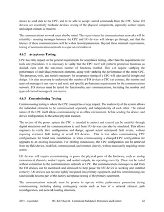
5.1.1 Protection Subsystem
The single line diagram of the substation is shown in Figure 35.
Figure 35. Single line diagram of 110 kV Olympic substation [62].
Protection and related automatics of the two 110 kV power lines include the following functions:
Line Differential Protection(87L) include an equipment at the remote terminal,
Three stages of Distance Protection (21P),
Four stages of Ground (Earth) Overcurrent Protection (51N),
Instantaneous Phase-to-phase Overcurrent Protection (50P),
Automatic Reclosing (79), and
Breaker Failure Protection (50BF).
110 kV busbars are protected by Busbar Differential Protection (87B) function.](https://image.slidesharecdn.com/ieee1-160309075548/85/slide-56-320.jpg)

![2015 – December WG K15 Report - Centralized Substation Protection and Control 56
Layer 5
Layer 4
Layer 3
Layer 2
Layer 1
Figure 36. The PACS structure of 110/10 kV Olympic substation in Northwest Siberia, Russia [62].
Figure 37. Connections of Main and BackUp PIDs to bay 110 kV apparatus [62].](https://image.slidesharecdn.com/ieee1-160309075548/85/slide-60-320.jpg)
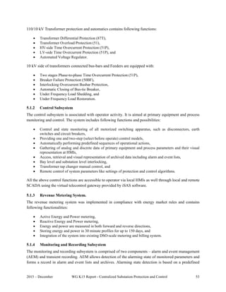
![2015 – December WG K15 Report - Centralized Substation Protection and Control 57
For redundancy reasons, the measurements of protection currents and voltages as well as circuit breaker
control and monitoring functions are duplicated by additional devices. The backup devices were placed in
separate cabinet in the switchyard as shown in Figure 38. The backup devices have characteristics like
BMPID, and have a fixed set of inputs and outputs in a rugged enclosure. Several devices are installed in
the 110 kV switchyard for redundancy of current and voltage measurements and circuit breaker control.
The rigid enclosure with IP 65 protection and extended operational temperature range of -550
C to +700
C
allowed the installation of such devices in the AIS substation without any additional shelters. Switchgear
emulators have been installed in the BMPID and BackUp PID cabinets as shown in Figure 39, since
interaction with primary equipment is not allowed during the trial operation period.
Figure 38. Main and BackUp PID cabinets installed at the 110 kV AIS [62].
(a) (b)
Figure 39. (a) BMPID cabinet with CB simulator and (b) BackUp PIDs outdoor cabinet with CB simulator [62].](https://image.slidesharecdn.com/ieee1-160309075548/85/slide-61-320.jpg)


![2015 – December WG K15 Report - Centralized Substation Protection and Control 61
6. EMERGING AND FUTURE APPLICATIONS
This section discusses some of the emerging and future applications for the power system protection and
control. This will require a paradigm shift in the way we approach the engineering, operation and
maintenance of the power system protection and control. Some of these applications can only be applied
with a CPC approach while others will significantly benefit in having the high-performance computing
platform at the substation. CPC will enable the development of newer applications for robust and flexible
protection and control system that can be replaced without any downtime at the end-of-useful life with an
overall reduced ownership cost with enhanced benefits to the user.
6.1 Dynamic State Estimation Based Protection
One of the most secure protection functions is differential protection. An additional advantage of
differential protection is that it does not need coordination with any other protection functions. The
principle of differential protection is that the sum of currents into a specific protection zone must equal to
zero. Thus if the relay monitors the sum of the currents and the sum is near zero then the differential
protection logic indicates normal operation. If the sum of the currents becomes substantially different than
zero the differential protection function concludes that there is an internal abnormality in the protection
zone.
The principle of monitoring a physical law (Kirchhoff’s current law in the case of differential protection)
can be extended to include other physical laws that a protection zone must obey, such as Kirchhoff’s
voltage law, electro thermal laws, magnetic flux versus voltage laws, etc. All the physical laws that a
protection zone must satisfy are expressed in the mathematical model of the protection zone. The
mathematical model is a set of equations in terms of the various variables of the model, such as voltage,
current, magnetic flux, temperature, etc. This principle is illustrated in Figure 40. Monitoring of the
validity of all these equations by measuring certain quantities and determining whether the measured
quantities satisfy the model equations can be done in a systematic and mathematically rigorous way via
dynamic state estimation (DSE) procedures. Details of the DSE can be found in the literature [63].
Figure 40. Illustration and comparison between Differential protection and Dynamic State Estimation based
protection (a.k.a. Setting-less protection).](https://image.slidesharecdn.com/ieee1-160309075548/85/slide-65-320.jpg)


![2015 – December WG K15 Report - Centralized Substation Protection and Control 67
In the area of analyzing time series, there are over a dozen feature extraction and dimension reduction
approaches. Some classical representatives are Discrete Fourier Transformation (DFT), Single Value
Decomposition (SVD), Principal Component Analysis (PCA), Discrete Cosine Transformation (DCT),
Discrete Wavelet Transformation (DWT). More recently, we see more advanced dimension reduction
approaches such as Piecewise Aggregate Approximation (PAA), Adaptive Piecewise Constant
Approximation (APCA), Chebyshev polynomials (CHEB), Symbolic Aggregate approXimation (SAX),
Indexable Piecewise Linear Approximation (IPLA). All these methods transform the original data series.
Another recent trend is to extract representative subsequences in the original data series as features. Time
series shapelets falls under this category. Despite all these approaches, there is no superior general feature
extraction method in all the situations.
In many cases, simple threshold based classification may not be possible. In such cases more advanced
methods are used to map features to classes. Supervised classification, which is the most relevant to our
purpose, involves previously known classes, and known representatives from each class, also called
ground truths. This information is used for making the classifier learn the features, so later, when a
feature set with unknown class is encountered by the classifier, it is able to classify the feature set
correctly. Well known classifiers include, but are not limited to Bayesian Classifier, k-Nearest-Neighbor
(kNN), Support Vector Machine (SVM), Expert Systems, Decision Tree, Neural Network, Genetic
Algorithms (GA). For patterns that may include information overlapping across classes (vague), Fuzzy
approach is also used.
Most relaying functions are essentially a classification. However, the classification is in most cases based
on thresholds and/or simple rules. Learning is not required for such functions. Moreover, availability of
real-world data for training any classifier-based relays is a challenge. The fact that such relays would have
to be retrained if used for another part of the power system is also a drawback.
6.2.1 Pattern Classification Based Protection
The concept of using pattern recognition is to employ well known heuristic methods that look at input
signals and based on particular signal properties (features) captured through techniques such as neural
network of fuzzy logic, classify such properties into domains that differentiate between faulted states and
normal states, and also allow classification of fault types and other fault properties such as location, fault
resistance, etc. [64]. An example of such an approach using neural networks is shown in Figure 45.
Further details are given in [65] and [66]. Going from left hand lower corner clockwise, one can note the
steps involved in this process, which is actually reduced to input-output space mapping using neural
networks.
Fuzzyfication of NN outputs: In this case, as shown in Figure 46, a k-nearest method enhanced with fuzzy
variables is used to fill in the gaps in the pattern space. Filling in the gaps is actually done by associating
the new patterns that fall in the space between the clusters to a given cluster based on the k-nearest
principle. In this case, the regions for category classification are extended beyond the clusters and any
new pattern can be recognized as a particular type of event. This way the last two steps in the input-output
space mapping shown at the beginning are accomplished. This example illustrates how differentiation
between different events, including fault types, can be made using just the input patterns and no settings
at all. This approach can be combined with the traditional approach to improve dependability/security, as
well as an automated analysis of a protection system [67], [68].](https://image.slidesharecdn.com/ieee1-160309075548/85/slide-71-320.jpg)

![2015 – December WG K15 Report - Centralized Substation Protection and Control 69
6.2.2 Wide Area Protection
Power blackouts over the world have shown that power systems, though carefully planned and protected,
suffer from unforeseen events triggering instability. Such events often include misoperations of relays that
result in unintended line trips, load shedding and generation trips. Such misoperations are unchecked
because global knowledge about the actual system condition is lacking. In the form of global knowledge
related to tripping, the control centers simply acquire relay trip flags, circuit breaker (CB) status flags, and
sometimes line currents and voltages for more reliable interpretation of these flags. These signals in most
cases do not convey whether the trip was as per design (correct) or it was a misoperation.
Blackout logs [69, 70, 71] have shown many instances of relay misoperations that either triggered or
accelerated the blackouts. It is crucial to realize that there is no way for system operators to know in near-
real-time if the tripping of a relay/CB was as per design (correctly responding to an event), or a
misoperation (operating in absence of event, or responding to an event it was not designed to detect).
Therefore, there is no way to reverse the misoperation and bring back the part of the system that could
avert a catastrophic outcome. In many of the blackout events described in [69-71], there was enough time
to reverse the triggering event, as well as load encroachment trips, which could have probably averted or
at least significantly alleviated the blackout.
A survey was performed by IEEE Power System Relaying Committee (PSRC) to evaluate the
performance of relay systems over four years (2000-2004) [72]. For four representative utilities, the
yearly misoperations during that period were 15.4%, 9.5%, 52.6%, and 28.6% at 345 kV voltage levels.
Comparable numbers were reported at other voltage levels. Even System Integrity Protection Schemes
(SIPS), which are specifically designed to prevent the system from hurtling into blackout, suffer from
misoperations [73].
From observations made above, it is evident that the power system can benefit from a global layer of
knowledge that oversees the relay and CB operation. This knowledge will either corroborate the relay
action, or invalidate it. In case the relay/CB action is invalidated, the resulting loss of system
component(s) should be brought back in, and the corresponding relay blocked for the time being. This
action can result in averting or significantly alleviating outage due to a potential blackout. It is important
to mention here that in case the supervisory knowledge is inaccurate, and results in erroneous disabling of
a relay, the backup relay will operate and remove the fault. This may result in some loss of selectivity, but
the advantage of this approach certainly outweighs this unintended outcome.
To work towards such a system, disturbance signatures from Phasor Measurement Units (PMUs) can be
utilized. Pattern recognition can be very useful to classify disturbances using features extracted from
disturbance files. Some studies in event identification using pattern recognition and classification have
already been reported in [74, 75, 76, 77]. Results in [74, 75] are based on computer simulations, whereas
study described in [76, 77] use real world PMU data from four PMUs for pattern recognition and
classification.](https://image.slidesharecdn.com/ieee1-160309075548/85/slide-73-320.jpg)

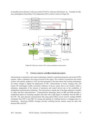

![2015 – December WG K15 Report - Centralized Substation Protection and Control 73
8. BIBLIOGRAPHY
1 A. Wright and P.G. Newbery, Electric Fuses, Institute of Electrical Engineers, Power Series 2, 1982, ISBN 0-
906048-78.
2 B. Lundqvist, “100 years of relay protection, the Swedish ABB relay history,” ABB Automation Products,
Substation Automation Division, [Online]. Available:
http://www05.abb.com/global/scot/scot296.nsf/veritydisplay/c1256d32004634bac1256e19006fd705/$File/PAP
ER_2001_08_en_100_Years_of_Relay_Protection__the_Swedish_ABB_Relay_History.pdf
3 Substation Control and Protection System – System Requirements Specification, Prepared by Westinghouse
Electric Corporation for EPRI Research Project RP-1359-1, April 1980.
4 Integrated Protection System for Rural Substations – SIPSUR, GE Protection & Control and Union Electrica
Fenosa (Spain) under a PIE research project, 1990.
5 P. Norberg, A. Fogelberg and A. Johnsson, “Field Experiences From Using PC Software for Protection and
Control of AC Substations," B3-208, CIGRE 2006 General Session.
6 M.S. Sachdev (Coordinator), et al., Computer Relaying, Tutorial Course Text, Institute of Electrical and
Electronic Engineers, New York, N.Y., U.S.A., Pub No. 79 EH0148-7-PWR, 1979.
7 M.S. Sachdev (Coordinator), et al. Microprocessor Relays and Protection Systems, Tutorial Course Text,
Institute of Electrical and Electronics Engineers, Piscataway, N.J. U.S.A., Pub No. 88EH0269-1-PWR, 1988.
8 M.S. Sachdev (Coordinator), et al, Advancements in Microprocessor Based Protection and Communication,
IEEE Tutorial Course, Institute of Electrical and Electronics Engineers, Piscataway, N.J. U.S.A., Pub No.
97TP120-0, 1997.
9 Understanding microprocessor-based technology applied to relaying, IEEE Power System Relaying Committee
WG I16 Report, 2009, Available at: http://www.pes-psrc.org/Reports/Apublications_new_format.htm.
10 F.H. Last and A. Stalewski, “Protective Relay Gear as a Part of Automatic Power System Control,” IEE
Conference Publication 16, Part I, March 1966.
11 Glossary of Some Telemetering Terms, Electrical Engineering, vol. 74, issue: 2, pp. 156, February 1955.
12 Supervisory Control and Data Acquisition (SCADA) in Liquid Pipelines, PB2005-917005, National
Transportation Safety Board.
13 Communications technology for protection systems, IEEE Power System Relaying Committee Report by WG
H9, 2013, Available at: http://www.pes-psrc.org/Reports/Apublications_new_format.htm.
14 IEEE Std C37.236™ - 2013 IEEE Guide for Power System Protective Relay Applications Over Digital
Communication Channels.
15 G. D. Rockefeller, “Fault protection with a digital computer,” IEEE Transactions on Power Apparatus and
Systems, Volume: PAS-88, Issue 4, 1969, 438-464.
16 G.B. Gilcrest, G.D. Rockefeller and E.A. Udren, “High-Speed Distance Relaying Using a Digital Computer I -
System Description,” IEEE Transactions on Power Apparatus and Systems, Volume:PAS-91, no. 3, pp. 1235 –
1243, 1972.](https://image.slidesharecdn.com/ieee1-160309075548/85/slide-77-320.jpg)
![2015 – December WG K15 Report - Centralized Substation Protection and Control 74
17 G.D. Rockefeller and E.A. Udren, “High-Speed Distance Relaying Using a Digital Computer II-Test Results,”
IEEE Transactions on Power Apparatus and Systems, vol. PAS-91, no. 3, pp. 1244 – 1258, 1972.
18 J.S. Deliyannides, M. Kezunovic, T.H. Schwalenstocker, “An Integrated Microprocessor Based Substation
Protection and Control System,” Developments in Power System Monitoring and Control, IEE, IEE Conference
Publ. No. 187, London, England, April 1980.
19 J.S. Deliyannides and E.A. Udren, “Design Criteria for an Integrated Microprocessor-based Substation
Protection and Control System,” IEEE Transactions on Power Apparatus and Systems, vol. PAS-101, no.6,
pp. 1664 – 1673, June 1982.
20 Nilsson et al., “Pros and cons of integrating protection and control in transmission substations,” IEEE
Transactions on Power Apparatus and Systems, vol. PAS-104, no. 5, pp. 1207 – 1224, May 1985.
21 E.A. Udren and J.S. Deliyannides, “Integrated System for Substation Relaying and Control Shows Benefits,”
IEEE Computer Application in Power, vol. PAS-101, no. 6, pp. 21 – 27, January 1989.
22 Madani et al., “Distribution Automation Strategies Challenges and Opportunities in a Changing Landscape,” in
Proc. IEEE Trans. Smart Grid, doi:10.1109/TSG.2014.2368382, vol. 6, no. 4, pp. 2157-2165, July 2015.
23 Bollen et al., “CIGRE/CIRED/IEEE Working Group C4.24 – Power Quality in the Future Grid – Status Report,”
in Proc. of the CIRED 23rd Inter. Conf. Electricity Dist., Lyon, France, June 2015, Paper 0181.
24 Das et al., “Distribution Automation Strategies: Evolution of Technologies and the Business Case,” in Proc.
IEEE Trans. Smart Grid, doi:10.1109/TSG.2014.2368393, vol. 6, no. 4, pp. 2166-2175, July 2015.
25 End-Of-Life Assessment of P&C Devices, IEEE Power System Relaying Committee WG I22 Report, 2015,
Available at http://www.pes-psrc.org/Reports/Apublications_new_format.htm.
26 C.F. Henville, “Multifunctional Protection IEDs – How Much Functionality is Too Much? Presented to the
PAC World Conference, Dublin, Ireland, June 21-24, 2010.
27 Optical Voltage and Current Sensor, NxtPhase Incorporated, Phoenix, AZ, US.
28 Lj. A. Kojovic, “Integration of Protection, Control, and Metering Functions,” 44th CIGRE Session, Paris,
France, 2012.
29 A. dos Santos, J. Lourenço, J. F. Martins, P. Monteiro, J. Fitch, T. Rahman , Lj. A. Kojovic, “Relay Protection
Solutions based on Non-Conventional Current Sensors in Actual Industrial/Utility Applications,” CIGRE Study
Committee B5 Colloquium, Belo Horizonte, Brazil, August 25-31, 2013.
30 Analog Inputs to Protective Relays from Electronic Voltage and Current Transducers, IEEE Standard
C37.92™-2005.
31 Instrument transformers – Part 8: Electronic current transformers, IEC Standard 60044-8™-2002.
32 Communication networks and systems in substations, IEC Standard 61850, 2004.
33 Guide for the Application of Rogowski Coils used for Protective Relaying Purposes, IEEE Standard C37.235™-
2007.
34 IEC 61869-1 Edition 1.0 2007-10 Instrument transformers – Part 1: General requirements.
35 IEC 61850-9-2 Edition 2.0 2011-09 Communication networks and systems for power utility automation – Part
9-2: Specific communication service mapping (SCSM) – Sampled values over ISO/IEC 8802-3.
36 High-availability Seamless Redundancy (HSR) and Parallel Redundancy Protocol (PRP), IEC 62439-3 Ed 2.0,
2012.
37 Official U.S. Government information about the Global Positioning System (GPS) and related topics
http://www.gps.gov/policy/legislation/loran-c/
38 Proposal for U.S. eLoran Service Gains Ground http://www.insidegnss.com/node/3853.
39 Inter Range Instrumentation Group (IRIG) mod B standard. [Online]. Available: http://irigb.com, May 1998.](https://image.slidesharecdn.com/ieee1-160309075548/85/slide-78-320.jpg)

![2015 – December WG K15 Report - Centralized Substation Protection and Control 76
59 M. Kezunovic and B. Perunicic, Fault Location, Wiley Encyclopedia of Electrical and Electronics Terminology,
Vol. 7, pp 276-285, John Wiley, 1999.
60 S.M. Brahma, “Fault location scheme for a multi-terminal transmission line using synchronized voltage
measurements,” IEEE Transactions on Power Delivery, Vol. 20, No. 2, pp. 1325 – 1331, April 2005.
61 T. Nguyen and Y. Liao, “Power quality disturbance classification based on adaptive neuro-fuzzy system,”
International Journal of Emerging Electric Power Systems, vol. 10, no. 3, Article 4, June 2009.
62 I. Dorofeyev, “First deployment of fully digital software-based PAC system on substation 110/10 kV - Basic
points of experience and first results,” PAC World Conference 2015, Glasgow, UK, June 29 –July 2, 2015.
63 Meliopoulos et al., “Setting-less Protection: Feasibility Study,” in Proc. of the 46th
Annual Hawaii International
Conference on System Sciences, Maui, HI, USA, January 7-10, 2013.
64 M. Kezunovic, “Translational knowledge: From collecting data to making decisions in a Smart Grid,” IEEE
Proceedings, April 2011.
65 S. Vasilić, M. Kezunović, “Fuzzy ART neural network algorithm for classifying the power system faults,” IEEE
Transactions on Power Delivery, Vol. 20, No. 2, pp 1306-1314, April 2005.
66 M. Kezunović, I. Rikalo, “Detect and classify faults using neural nets,” IEEE Computer Applications in Power,
Vol. 9, No. 4, pp 42-47, October 1996.
67 N. Zhang and M. Kezunović, “Transmission line boundary protection using wavelet transform and neural
network,” IEEE Transactions on Power Delivery, Vol. 22, No. 2, pp 859-869, April 2007.
68 N. Zhang and M. Kezunović, “A Real Time Fault Analysis Tool for Monitoring Operation of Transmission
Line Protective Relay,” Electric Power Systems Research Journal, Vol. 77, No. 3-4, pp 361-370, March 2007.
69 North American Electric Reliability Council, 1996 system disturbances: Review of selected 1996 electric system
disturbances in North America. [Online]. Available:
http://www.nerc.com/pa/rrm/ea/System%20Disturbance%20Reports%20DL/1996SystemDisturbance.pdf.
70 North American Electric Reliability Council, Technical analysis of the August 14, 2003, blackout: What
happened, why, and what did we learn? [Online]. Available:
http://www.nerc.com/docs/docs/blackout/NERC_Final_Blackout_Report_07_13_04.pdf.
71 North American Electric Reliability Council and Federal Energy Regulatory Commission, Arizona - southern
California outages on September 8, 2011: Causes and recommendations. [Online]. Available:
http://www.ferc.gov/legal/staff-reports/04-27-2012-ferc-nerc-report.pdf.
72 Transmission relay systems performance comparison, IEEE Power System Relaying Committee Report by WG
I17, 2005, Available at: http://www.pes-psrc.org/Reports/Apublications_new_format.htm.
73 D. C. E. de la Garza, Masters Thesis, Hidden Failures in Protection Systems and its Impact on Power System
Wide-area Disturbances, Virginia Polytechnic Institute and State University, 2000.
74 W. Gao and J. Ning, “Wavelet-based disturbance analysis for power system wide-area monitoring,” IEEE
Transactions on Smart Grid, vol. 2, no. 1, pp. 121 –130, March 2011.
75 J. Ma, Y. V. Makarov, R. Diao, P. V. Etingov, J. E. Dagle, and E. De Tuglie, “The characteristic ellipsoid
methodology and its application in power systems,” IEEE Transactions on Power Systems, vol. 27, no. 4, pp.
2206 –2214, Nov. 2012.
76 O. P. Dahal, S. M. Brahma and H. Cao, “Comprehensive clustering of disturbance events recorded by phasor
measurement units,” IEEE Trans. on Power Delivery, vol. 29, no. 3, pp. 1390 – 1397, 2014.
77 O. P. Dahal, H. Cao, S. M. Brahma, “Evaluating performance of classifiers for supervisory protection using
disturbance data from phasor measurement units”, in Proc. ISGT Europe, Istanbul, Turkey, October 2014.](https://image.slidesharecdn.com/ieee1-160309075548/85/slide-80-320.jpg)


