The document discusses various topics related to springs including types of springs, materials used for springs, stresses in springs, deflection of springs, buckling of springs, energy stored in springs, springs connected in series and parallel, leaf springs, and torsion springs. It provides definitions and key terms for different types of springs such as helical springs, conical springs, volute springs, torsion springs, leaf springs, and disc springs. It also discusses common materials used for helical springs and factors that influence material selection such as service conditions.
Spring Design, Helical Springs, compression & Extension springs, spring design procedure leaf spring, multi-leaf springs design process and analysis, Role of Spring index in spring design. Springs for Fluctuating loads.
Spring Design, Helical Springs, compression & Extension springs, spring design procedure leaf spring, multi-leaf springs design process and analysis, Role of Spring index in spring design. Springs for Fluctuating loads.
Spring is an elastic body whose function is to distort when loaded and to recover its original shape when the load is removed.
APPLICATION OF SPRINGS
To apply forces as in brakes, clutches and spring loaded valves.
To store energy as in watches, toys.
To measure forces as in spring balance and engine indicators.
To cushion, absorb or control energy due to either shock or vibration as in car.The material of the spring should have
high fatigue strength,
high ductility,
high resilience and
creep resistant.
It largely depends upon the size and service.
The strength of the wires varies with size, smaller size wires have greater strength and less ductility, due to the greater degree of cold working.
Severe service means rapid continuous loading where the ratio of minimum to maximum load (or stress) is one-half or less, as in automotive valve springs.
Average service includes the same stress range as in severe service but with only intermittent operation, as in engine governor springs and automobile suspension springs.
Light service includes springs subjected to loads that are static or very infrequently varied, as in safety valve springs.
The springs are mostly made from oil-tempered carbon steel wires containing 0.60 to 0.70 per cent carbon and 0.60 to 1.0 per cent manganese.
UNIT-4-ENERGY STORING ELEMENTS AND ENGINE COMPONENTS.pptxkarthi keyan
ENERGY STORING ELEMENTS AND ENGINE COMPONENTS
Springs – Design of helical springs – Design of Leaf, Belleville springs and Torsion springs – Flywheels considering stresses in rims and arms for engines and punching machines. Design of Crankshaft.
CFD Simulation of By-pass Flow in a HRSG module by R&R Consult.pptxR&R Consult
CFD analysis is incredibly effective at solving mysteries and improving the performance of complex systems!
Here's a great example: At a large natural gas-fired power plant, where they use waste heat to generate steam and energy, they were puzzled that their boiler wasn't producing as much steam as expected.
R&R and Tetra Engineering Group Inc. were asked to solve the issue with reduced steam production.
An inspection had shown that a significant amount of hot flue gas was bypassing the boiler tubes, where the heat was supposed to be transferred.
R&R Consult conducted a CFD analysis, which revealed that 6.3% of the flue gas was bypassing the boiler tubes without transferring heat. The analysis also showed that the flue gas was instead being directed along the sides of the boiler and between the modules that were supposed to capture the heat. This was the cause of the reduced performance.
Based on our results, Tetra Engineering installed covering plates to reduce the bypass flow. This improved the boiler's performance and increased electricity production.
It is always satisfying when we can help solve complex challenges like this. Do your systems also need a check-up or optimization? Give us a call!
Work done in cooperation with James Malloy and David Moelling from Tetra Engineering.
More examples of our work https://www.r-r-consult.dk/en/cases-en/
NO1 Uk best vashikaran specialist in delhi vashikaran baba near me online vas...Amil Baba Dawood bangali
Contact with Dawood Bhai Just call on +92322-6382012 and we'll help you. We'll solve all your problems within 12 to 24 hours and with 101% guarantee and with astrology systematic. If you want to take any personal or professional advice then also you can call us on +92322-6382012 , ONLINE LOVE PROBLEM & Other all types of Daily Life Problem's.Then CALL or WHATSAPP us on +92322-6382012 and Get all these problems solutions here by Amil Baba DAWOOD BANGALI
#vashikaranspecialist #astrologer #palmistry #amliyaat #taweez #manpasandshadi #horoscope #spiritual #lovelife #lovespell #marriagespell#aamilbabainpakistan #amilbabainkarachi #powerfullblackmagicspell #kalajadumantarspecialist #realamilbaba #AmilbabainPakistan #astrologerincanada #astrologerindubai #lovespellsmaster #kalajaduspecialist #lovespellsthatwork #aamilbabainlahore#blackmagicformarriage #aamilbaba #kalajadu #kalailam #taweez #wazifaexpert #jadumantar #vashikaranspecialist #astrologer #palmistry #amliyaat #taweez #manpasandshadi #horoscope #spiritual #lovelife #lovespell #marriagespell#aamilbabainpakistan #amilbabainkarachi #powerfullblackmagicspell #kalajadumantarspecialist #realamilbaba #AmilbabainPakistan #astrologerincanada #astrologerindubai #lovespellsmaster #kalajaduspecialist #lovespellsthatwork #aamilbabainlahore #blackmagicforlove #blackmagicformarriage #aamilbaba #kalajadu #kalailam #taweez #wazifaexpert #jadumantar #vashikaranspecialist #astrologer #palmistry #amliyaat #taweez #manpasandshadi #horoscope #spiritual #lovelife #lovespell #marriagespell#aamilbabainpakistan #amilbabainkarachi #powerfullblackmagicspell #kalajadumantarspecialist #realamilbaba #AmilbabainPakistan #astrologerincanada #astrologerindubai #lovespellsmaster #kalajaduspecialist #lovespellsthatwork #aamilbabainlahore #Amilbabainuk #amilbabainspain #amilbabaindubai #Amilbabainnorway #amilbabainkrachi #amilbabainlahore #amilbabaingujranwalan #amilbabainislamabad
Overview of the fundamental roles in Hydropower generation and the components involved in wider Electrical Engineering.
This paper presents the design and construction of hydroelectric dams from the hydrologist’s survey of the valley before construction, all aspects and involved disciplines, fluid dynamics, structural engineering, generation and mains frequency regulation to the very transmission of power through the network in the United Kingdom.
Author: Robbie Edward Sayers
Collaborators and co editors: Charlie Sims and Connor Healey.
(C) 2024 Robbie E. Sayers
Industrial Training at Shahjalal Fertilizer Company Limited (SFCL)MdTanvirMahtab2
This presentation is about the working procedure of Shahjalal Fertilizer Company Limited (SFCL). A Govt. owned Company of Bangladesh Chemical Industries Corporation under Ministry of Industries.
Cosmetic shop management system project report.pdfKamal Acharya
Buying new cosmetic products is difficult. It can even be scary for those who have sensitive skin and are prone to skin trouble. The information needed to alleviate this problem is on the back of each product, but it's thought to interpret those ingredient lists unless you have a background in chemistry.
Instead of buying and hoping for the best, we can use data science to help us predict which products may be good fits for us. It includes various function programs to do the above mentioned tasks.
Data file handling has been effectively used in the program.
The automated cosmetic shop management system should deal with the automation of general workflow and administration process of the shop. The main processes of the system focus on customer's request where the system is able to search the most appropriate products and deliver it to the customers. It should help the employees to quickly identify the list of cosmetic product that have reached the minimum quantity and also keep a track of expired date for each cosmetic product. It should help the employees to find the rack number in which the product is placed.It is also Faster and more efficient way.
Hybrid optimization of pumped hydro system and solar- Engr. Abdul-Azeez.pdffxintegritypublishin
Advancements in technology unveil a myriad of electrical and electronic breakthroughs geared towards efficiently harnessing limited resources to meet human energy demands. The optimization of hybrid solar PV panels and pumped hydro energy supply systems plays a pivotal role in utilizing natural resources effectively. This initiative not only benefits humanity but also fosters environmental sustainability. The study investigated the design optimization of these hybrid systems, focusing on understanding solar radiation patterns, identifying geographical influences on solar radiation, formulating a mathematical model for system optimization, and determining the optimal configuration of PV panels and pumped hydro storage. Through a comparative analysis approach and eight weeks of data collection, the study addressed key research questions related to solar radiation patterns and optimal system design. The findings highlighted regions with heightened solar radiation levels, showcasing substantial potential for power generation and emphasizing the system's efficiency. Optimizing system design significantly boosted power generation, promoted renewable energy utilization, and enhanced energy storage capacity. The study underscored the benefits of optimizing hybrid solar PV panels and pumped hydro energy supply systems for sustainable energy usage. Optimizing the design of solar PV panels and pumped hydro energy supply systems as examined across diverse climatic conditions in a developing country, not only enhances power generation but also improves the integration of renewable energy sources and boosts energy storage capacities, particularly beneficial for less economically prosperous regions. Additionally, the study provides valuable insights for advancing energy research in economically viable areas. Recommendations included conducting site-specific assessments, utilizing advanced modeling tools, implementing regular maintenance protocols, and enhancing communication among system components.
Sachpazis:Terzaghi Bearing Capacity Estimation in simple terms with Calculati...Dr.Costas Sachpazis
Terzaghi's soil bearing capacity theory, developed by Karl Terzaghi, is a fundamental principle in geotechnical engineering used to determine the bearing capacity of shallow foundations. This theory provides a method to calculate the ultimate bearing capacity of soil, which is the maximum load per unit area that the soil can support without undergoing shear failure. The Calculation HTML Code included.
3. 1 Notations
1.1 Terms used in compression springs
• n = Total number of coils.
• d = Diameter of the wire.
• D = Mean diameter of the coil.
• d = Diameter of the spring wire.
• W = Load.
• δ = Deflection of the spring.
• LF = Free length of the spring.
• LS = Solid length of the spring.
• p = Pitch of the coils.
• n = Number of active turns.
1.2 Stresses in helical springs of circular wire
• D = Mean diameter of the spring coil.
• d = Diameter of the spring wire.
• n = Number of active coils.
• G = Modulus of rigidity for the spring material.
• W = Axial load on the spring.
• τ = Maximum shear stress induced in the wire.
• C = Spring index = D/d.
• p = Pitch of the coils.
• δ = Deflection of the spring, as a result of an axial
load W.
• KS = Stress factor due to shear.
• KC = Stress concentration factor due to curva-
ture.
1.3 Deflection of helical springs of circular wire
• θ = Angular deflection of the wire when acted
upon by the torque T.
• J = Polar moment of inertia of the spring wire.
• G = Modulus of rigidity for the material of the
spring wire.
• d = being the diameter of spring wire.
1.4 Eccentric loading of springs
• D = The mean diameter of the spring.
1.5 Buckling of compression springs
• k = Spring rate or stiffness of the spring = W/δ.
• LF = Free length of the spring.
• KB = Buckling factor depending upon the ratio
LF /D.
1.6 Surge in springs
• d = Diameter of the wire.
• D = Mean diameter of the spring.
• n = Number of active turns.
• G = Modulus of rigidity.
• g = Acceleration due to gravity.
• ρ = Density of the material of the spring.
1.7 Energy stored in helical springs of circular
wire
• W = Load applied on the spring.
• δ = Deflection produced in the spring due to the
load W.
1.8 Stress and deflection in helical springs of
non-circular wire
• b = Side of the square.
1.9 Springs in series
• W = Load carried by the springs.
• δ1 = Deflection of spring 1.
• δ2 = Deflection of spring 2.
• k1 = Stiffness of spring 1 = W/δ1
• k2 = Stiffness of spring 2 = W/δ2
• k = Combined stiffness of the springs.
1.10 Springs in parallel
• W = Load carried by the springs.
• W1 = Load shared by spring 1.
• W2 = Load shared by spring 2.
• k1 = Stiffness of spring 1.
• k2 = Stiffness of spring 2.
• k = Combined stiffness of the springs.
• δ = Deflection produced.
4. 1.11 Concentric or composite springs
• W = Axial load.
• W1 = Load shared by outer spring.
• W2 = Load shared by inner spring.
• d1 = Diameter of spring wire of outer spring.
• d2 = Diameter of spring wire of inner spring.
• D1 = Mean diameter of outer spring.
• D2 = Mean diameter of inner spring.
• δ1 = Deflection of outer spring.
• δ2 = Deflection of inner spring.
• n1 = Number of active turns of outer spring.
• n2 = Number of active turns of inner spring.
1.12 Helical torsion springs
• K = Wahl’s stress factor = 4C2−C−1
4C2−4C
• C = Spring index.
• M = Bending moment = W × y.
• W = Load acting on the spring.
• y = Distance of load from the spring axis.
• d = Diameter of spring wire.
• l = Length of the wire = πDn.
• E = Young’s modulus.
• I = Moment of inertia = π
64
× d4
.
• D = Diameter of the spring.
• n = Number of turns.
1.13 Flat spiral spring
• W = Force applied at the outer end A of the
spring.
• y = Distance of center of gravity of the spring
from A.
• l = Length of strip forming the spring.
• b = Width of strip.
• t = Thickness of strip.
• I = Moment of inertia of the spring section =
b.t3
/12.
• Z = Section modulus of the spring section =
b.t2
/6
1.14 Leaf springs
• t = Thickness of plate.
• b = Width of plate.
• L = Length of plate or distance of the load Wfrom
the cantilever end.
• n = Number of graduated leaves.
1.15 Length of leaf spring leaves
• 2L1 = Length of span or overall length of the
spring.
• l = Width of band or distance between centers of
U-bolts. It is the ineffective length of the spring.
• nF = Number of full length leaves.
• nG = Number of graduated leaves.
• n = Total number of leaves = nF + nG.
• d = Inside diameter of eye.
• t = Thickness of master leaf.
• L1 = Half span of the spring.
5. 2 Introduction
A spring is defined as an elastic body, whose function is to distort when loaded and to recover its original shape
when the load is removed. The various important applications of springs are as follows:
1. To cushion, absorb or control energy due to either shock or vibration as in car springs, railway buffers,
air-craft landing gears, shock absorbers and vibration dampers.
2. To apply forces, as in brakes, clutches and spring-loaded valves.
3. To control motion by maintaining contact between two elements as in cams and followers.
4. To measure forces, as in spring balances and engine indicators.
5. To store energy, as in watches, toys, etc.
3 Types of Springs
Though there are many types of the springs, yet the following, according to their shape, are important from the
subject point of view.
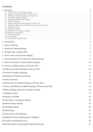
1. Helical springs. The helical springs are made up of a wire coiled in the form of a helix and is primarily
intended for compressive or tensile loads. The cross-section of the wire from which the spring is made may
be circular, square or rectangular. The two forms of helical springs are compression helical spring as
shown in Fig. 1 (a) and tension helical spring as shown in Fig. 1 (b).
Figure 1: Helical springs.
The helical springs are said to be closely coiled when the spring wire is coiled so close that the plane
containing each turn is nearly at right angles to the axis of the helix and the wire is subjected to torsion. In
other words, in a closely coiled helical spring, the helix angle is very small, it is usually less than 10o
. The
major stresses produced in helical springs are shear stresses due to twisting. The load applied is parallel
to or along the axis of the spring.
In open coiled helical springs, the spring wire is coiled in such a way that there is a gap between the
two consecutive turns, as a result of which the helix angle is large. Since the application of open coiled
helical springs are limited, therefore our discussion shall confine to closely coiled helical springs only.
The helical springs have the following advantages:
(a) These are easy to manufacture.
(b) These are available in wide range.
(c) These are reliable.
(d) These have constant spring rate.
(e) Their performance can be predicted more accurately.
(f) Their characteristics can be varied by changing dimensions.
2. Conical and volute springs. The conical and volute springs, as shown in Fig. 2, are used in special
applications where a telescoping spring or a spring with a spring rate that increases with the load is desired.
The conical spring, as shown in Fig. 2 (a), is wound with a uniform pitch whereas the volute springs, as
shown in Fig. 2 (b), are wound in the form of paraboloid with constant pitch and lead angles. The
springs may be made either partially or completely telescoping. In either case, the number of active coils
gradually decreases. The decreasing number of coils results in an increasing spring rate. This characteristic
6. is sometimes utilized in vibration problems where springs are used to support a body that has a varying
mass.
The major stresses produced in conical and volute springs are also shear stresses due to twisting.
Figure 2: Conical and volute springs.
3. Torsion springs. These springs may be of helical or spiral type as shown in Fig. 3. The helical
type may be used only in applications where the load tends to wind up the spring and are used in various
electrical mechanisms. The spiral type is also used where the load tends to increase the number of coils
and when made of flat strip are used in watches and clocks.
The major stresses produced in torsion springs are tensile and compressive due to bending.
Figure 3: Torsion springs.
4. Laminated or leaf springs. The laminated or leaf spring (also known as flat spring or carriage spring)
consists of a number of flat plates (known as leaves) of varying lengths held together by means of clamps
and bolts, as shown in Fig. 4. These are mostly used in automobiles.
The major stresses produced in leaf springs are tensile and compressive stresses.
Figure 4: Laminated or leaf springs.
7. 5. Disc or bellevile springs. These springs consist of a number of conical discs held together against
slipping by a central bolt or tube as shown in Fig. 5. These springs are used in applications where high
spring rates and compact spring units are required.
The major stresses produced in disc or bellevile springs are tensile and compressive stresses.
Figure 5: Disc or bellevile springs.
6. Special purpose springs. These springs are air or liquid springs, rubber springs, ring springs etc. The
fluids (air or liquid) can behave as a compression spring. These springs are used for special types of
application only.
4 Material for Helical Springs
The material of the spring should have high fatigue strength, high ductility, high resilience and it should be
creep resistant. It largely depends upon the service for which they are used i.e. severe service, average service
or light service.
Severe service means rapid continuous loading where the ratio of minimum to maximum load (or stress) is
one-half or less, as in automotive valve springs.
Average service includes the same stress range as in severe service but with only intermittent operation, as
in engine governor springs and automobile suspension springs.
Light service includes springs subjected to loads that are static or very infrequently varied, as in safety valve
springs.
The springs are mostly made from oil-tempered carbon steel wires containing 0.60 to 0.70 per cent carbon and
0.60 to 1.0 per cent manganese. Music wire is used for small springs. Non-ferrous materials like phosphor
bronze, beryllium copper, monel metal, brass etc., may be used in special cases to increase fatigue resistance,
temperature resistance and corrosion resistance.
Table 23.1 shows the values of allowable shear stress, modulus of rigidity and modulus of elasticity for various
materials used for springs.
The helical springs are either cold formed or hot formed depending upon the size of the wire. Wires of small
sizes (less than 10 mm diameter) are usually wound cold whereas larger size wires are wound hot. The strength
of the wires varies with size, smaller size wires have greater strength and less ductility, due to the greater degree
of cold working.
8. 5 Standard Size of Spring Wire
The standard size of spring wire may be selected from the following table :
6 Terms used in Compression Springs
The following terms used in connection with compression springs are important from the subject point of view.
1. Solid length. When the compression spring is compressed until the coils come in contact with each other,
then the spring is said to be solid. The solid length of a spring is the product of total number of coils and
the diameter of the wire. Mathematically,
Solid length of the spring,
LS = n d
2. Free length. The free length of a compression spring is the length of the spring in the free or unloaded
condition. It is equal to the solid length plus the maximum deflection or compression of the spring and the
clearance between the adjacent coils (when fully compressed). Mathematically,
Free length of the spring,
LF = Solid length + Maximum compression + Clearance between adjacent coils (or clash allowance)
= n d + δmax + 0.15 δmax
The following relation may also be used to find the free length of the spring, i.e.
LF = n d + δmax + (n − 1) × 1 mm
In this expression, the clearance between the two adjacent coils is taken as 1 mm.
Figure 6: Compression spring nomenclature.
9. 3. Spring index. The spring index is defined as the ratio of the mean diameter of the coil to the diameter
of the wire. Mathematically,
Spring index,
C =
D
d
4. Spring rate. The spring rate (or stiffness or spring constant) is defined as the load required per unit
deflection of the spring. Mathematically,
Spring rate,
k =
W
δ
5. Pitch. The pitch of the coil is defined as the axial distance between adjacent coils in uncompressed state.
Mathematically,
Pitch of the coil,
p =
Free length
n − 1
The pitch of the coil may also be obtained by using the following relation, i.e. Pitch of the coil,
p =
LF − LS
n
+ d
In choosing the pitch of the coils, the following points should be noted :
(a) The pitch of the coils should be such that if the spring is accidentally or carelessly compressed, the
stress does not increase the yield point stress in torsion.
(b) The spring should not close up before the maximum service load is reached.
Note: In designing a tension spring (See Example 23.8), the minimum gap between two coils when the
spring is in the free state is taken as 1 mm. Thus the free length of the spring,
LF = n d + (n − 1)
and pitch of the coil,
p =
LF
n − 1
7 End Connections for Compression Helical Springs
The end connections for compression helical springs are suitably formed in order to apply the load. Various
forms of end connections are shown in Fig. 7.
Figure 7: End connections for compression helical spring.
10. It may be noted that part of the coil which is in contact with the seat does not contribute to spring action and
hence are termed as inactive coils. The turns which impart spring action are known as active turns. As
the load increases, the number of inactive coils also increases due to seating of the end coils and the amount of
increase varies from 0.5 to 1 turn at the usual working loads. The following table shows the total number of
turns, solid length and free length for different types of end connections.
8 End Connections for Tension Helical Springs
The tensile springs are provided with hooks or loops as shown in Fig. 8. These loops may be made by turning
whole coil or half of the coil. In a tension spring, large stress concentration is produced at the loop or other
attaching device of tension spring.
The main disadvantage of tension spring is the failure of the spring when the wire breaks. A compression spring
used for carrying a tensile load is shown in Fig. 9.
Figure 8: End connection for tension helical springs.
Figure 9: Compression spring for carrying tensile load.
Note: The total number of turns of a tension helical spring must be equal to the number of turns (n) between
the points where the loops start plus the equivalent turns for the loops. It has been found experimentally that
half turn should be added for each loop. Thus for a spring having loops on both ends, the total number of
active turns,
n = n + 1
11. 9 Stresses in Helical Springs of Circular Wire
Consider a helical compression spring made of circular wire and subjected to an axial load W, as shown in Fig.
10 (a).
Now consider a part of the compression spring as shown in Fig. 10 (b). The load W tends to rotate the wire
due to the twisting moment (T) set up in the wire. Thus torsional shear stress is induced in the wire.
A little consideration will show that part of the spring, as shown in Fig. 10 (b), is in equilibrium under the
action of two forces Wand the twisting moment T. We know that the twisting moment,
T = W ×
D
2
=
π
16
× τ1 × d3
1
∴ τ1 =
8WD
πd3
Figure 10:
The torsional shear stress diagram is shown in Fig. 11 (a). In addition to the torsional shear stress (τ1) induced
in the wire, the following stresses also act on the wire :
1. Direct shear stress due to the load W, and
2. Stress due to curvature of wire.
We know that direct shear stress due to the load W,
τ2 =
Load
Cross-sectional area of the wire
=
W
π
4
× d2
=
4W
πd2
The direct shear stress diagram is shown in Fig. 11 (b) and the resultant diagram of torsional shear stress and
direct shear stress is shown in Fig. 11 (c).
We know that the resultant shear stress induced in the wire,
τ = tau1 ± τ2 =
8WD
πd3
±
4W
πd2
The positive sign is used for the inner edge of the wire and negative sign is used for the outer edge of the
wire. Since the stress is maximum at the inner edge of the wire, therefore
Maximum shear stress induced in the wire,
= Torsional shear stress + Direct shear stress
=
8WD
πd3
+
4W
πd2
=
8WD
πd3
1 +
d
2D
12. =
8WD
πd3
1 +
1
2C
= KS ×
8WD
πd3
(1)
Where,
KS = 1 +
1
2C
From the above equation, it can be observed that the effect of direct shear 8WD
πd3 × 1
2C
is appreciable for springs
of small spring index C. Also we have neglected the effect of wire curvature in equation 1. It may be noted that
when the springs are subjected to static loads, the effect of wire curvature may be neglected, because yielding
of the material will relieve the stresses.
Figure 11: Superposition of stresses in a helical spring.
In order to consider the effects of both direct shear as well as curvature of the wire, a Wahl’s stress factor (K)
introduced by A.M. Wahl may be used. The resultant diagram of torsional shear, direct shear and curvature
shear stress is shown in Fig. 11 (d).
∴ Maximum shear stress induced in the wire,
τ = K ×
8WD
πd3
= K ×
8WC
πd2
Where,
K =
4C − 1
4C − 4
+
0.615
C
The values of K for a given spring index (C) may be obtained from the graph as shown in Fig. 12.
We see from Fig. 12 that Wahl’s stress factor increases very rapidly as the spring index decreases. The spring
mostly used in machinery have spring index above 3.
13. Figure 12: Wahl’s stress factor for helical springs.
Note: The Wahl’s stress factor (K) may be considered as composed of two sub-factors, KS and KC , such that
K = KS × KC
10 Deflection of Helical Springs of Circular Wire
Total active length of the wire,
l = Length of one coil × No. of active coils = πD × n
∴ Axial deflection of the spring,
δ = θ × D/2
We also know that
T
J
=
τ
D/2
=
Gθ
l
∴ θ =
Tl
JG
J =
π
32
× d4
∴ θ =
Tl
JG
=
W × D
2
πDn
π
32
× d4G
=
16WD2
n
Gd4
∴ δ =
16WD2
n
Gd4
×
D
2
=
8WD3
n
Gd4
=
8WC3
n
Gd
The stiffness of the spring or spring rate,
W
δ
=
Gd4
8D3n
=
Gd
8C3n
= constant
11 Eccentric Loading of Springs
Sometimes, the load on the springs does not coincide with the axis of the spring, i.e. the spring is subjected to
an eccentric load. In such cases, not only the safe load for the spring reduces, the stiffness of the spring is also
affected. The eccentric load on the spring increases the stress on one side of the spring and decreases on the
other side. When the load is offset by a distance e from the spring axis, then the safe load on the spring may
be obtained by multiplying the axial load by the factor
D
2 e + D
14. 12 Buckling of Compression Springs
It has been found experimentally that when the free length of the spring (LF ) is more than four times the mean
or pitch diameter (D), then the spring behaves like a column and may fail by buckling at a comparatively low
load as shown in Fig. 13 The critical axial load (Wcr) that causes buckling may be calculated by using the
following relation, i.e.
Wcr = k × KB × LF
Figure 13: Buckling of compression springs.
The buckling factor (KB) for the hinged end and built-in end springs may be taken from the following table.
It may be noted that a hinged end spring is one which is supported on pivots at both ends as in case of
springs having plain ends where as a built-in end spring is one in which a squared and ground end spring is
compressed between two rigid and parallel flat plates.
It order to avoid the buckling of spring, it is either mounted on a central rod or located on a tube. When the
spring is located on a tube, the clearance between the tube walls and the spring should be kept as small as
possible, but it must be sufficient to allow for increase in spring diameter during compression.
13 Surge in Springs
When one end of a helical spring is resting on a rigid support and the other end is loaded suddenly, then all
the coils of the spring will not suddenly deflect equally, because some time is required for the propagation of
stress along the spring wire. A little consideration will show that in the beginning, the end coils of the spring in
contact with the applied load takes up whole of the deflection and then it transmits a large part of its deflection
to the adjacent coils. In this way, a wave of compression propagates through the coils to the supported end from
where it is reflected back to the deflected end. This wave of compression travels along the spring indefinitely.
If the applied load is of fluctuating type as in the case of valve spring in internal combustion engines and if the
time interval between the load applications is equal to the time required for the wave to travel from one end to
the other end, then resonance will occur. This results in very large deflections of the coils and correspondingly
very high stresses. Under these conditions, it is just possible that the spring may fail. This phenomenon is
called surge.
It has been found that the natural frequency of spring should be atleast twenty times the frequency of application
of a periodic load in order to avoid resonance with all harmonic frequencies upto twentieth order. The natural
15. frequency for springs clamped between two plates is given by
fn =
d
2πD2n
6Gg
ρ
cycles/s
The surge in springs may be eliminated by using the following methods :
1. By using friction dampers on the center coils so that the wave propagation dies out.
2. By using springs of high natural frequency.
3. By using springs having pitch of the coils near the ends different than at the center to have different natural
frequencies.
14 Energy Stored in Helical Springs of Circular Wire
We know that the springs are used for storing energy which is equal to the work done on it by some external
load.
Assuming that the load is applied gradually, the energy stored in a spring is,
U =
1
2
Wδ
We have already discussed that the maximum shear stress induced in the spring wire,
τ = K ×
8WD
πd3
⇒ W =
πd3
τ
8KD
We know that deflection of the spring,
δ =
8WD3
n
Gd4
=
8 × πd3
τ
8KD
×
D3
n
Gd4
=
πτD2
n
KdG
Substituting the values of W and δ, we have
U =
1
2
×
πd3
τ
8KD
×
πτD2
n
KdG
=
τ2
4K2G
(πDn)
π
4
× d2
=
τ2
4K2G
× V
where,
V = Volume of the spring wire
= Length of spring wire × Cross-sectional area of spring wire
= (πDn)
π
4
× d2
Note: When a load (say P) falls on a spring through a height h, then the energy absorbed in a spring is given
by
U = P(h + δ) =
1
2
Wδ
15 Stress and Deflection in Helical Springs of Non-circular Wire
The helical springs may be made of non-circular wire such as rectangular or square wire, in order to provide
greater resilience in a given space. However these springs have the following main disadvantages :
1. The quality of material used for springs is not so good.
2. The shape of the wire does not remain square or rectangular while forming helix, resulting in trapezoidal
cross-sections. It reduces the energy absorbing capacity of the spring.
3. The stress distribution is not as favourable as for circular wires. But this effect is negligible where loading
is of static nature.
16. For springs made of rectangular wire, as shown in Fig. 14, the maxi-mum shear stress is given by
τ = K ×
WD(1.5b + 0.9t)
b2t2
This expression is applicable when the longer side (i.e. t > b) is parallel to the axis of the spring. But when the
shorter side (i.e. t < b) is parallel to the axis of the spring, then maximum shear stress,
τ = K ×
WD(1.5b + 0.9t)
b2t2
and deflection of the spring,
δ =
2.45 WD3
n
Gb3 (t − 0.56 b)
For springs made of square wire, the dimensions b and t are equal. Therefore, the maximum shear stress is given
by
τ = K ×
2.4 WD
b3
and deflection of the spring,
δ =
5.568 WD3
n
Gb4
=
5.568 WC3
n
Gb
Note: In the above expressions,
K =
4C − 1
4C − 4
+
0.615
C
, and C =
D
b
Figure 14: Spring of rectangular wire.
16 Helical Springs Subjected to Fatigue Loading
The helical springs subjected to fatigue loading are designed by using the Soderberg line method. The spring
materials are usually tested for torsional endurance strength under a repeated stress that varies from zero to a
maximum. Since the springs are ordinarily loaded in one direction only (the load in springs is never reversed in
nature), therefore a modified Soderberg diagram is used for springs, as shown in Fig. 15.
The endurance limit for reversed loading is shown at point A where the mean shear stress is equal to τe/2 and
the variable shear stress is also equal to τe/2. A line drawn from A to B (the yield point in shear, τy) gives the
Soderberg’s failure stress line. If a suitable factor of safety (F.S.) is applied to the yield strength (τy), a safe
stress line CD may be drawn parallel to the line AB, as shown in Fig. 15. Consider a design point P on the
line CD. Now the value of factor of safety may be obtained as discussed below : From similar triangles PQD
and AOB, we have
PQ
QD
=
OA
OB
or
PQ
O1D − O1Q
=
OA
O1B − O1O
τv
τy
F.S.
− τm
=
τe/2
τy − τe
2
=
τe
2τy − τe
∴ 2τvτy − τvτe =
τeτy
F.S.
− τmτe
17. ∴
τeτy
F.S.
= 2τvτy − τvτe + τmτe
∴
1
F.S.
=
τm − τv
τy
+
2τv
τe
Figure 15: Modified Soderberg method for helical springs.
Notes:
1. The expression for the factor of safety (F.S.) may be written as
F.S. =
τy
τm − τv + 2τvτy
τe
2. The value of mean shear stress (τm) is calculated by using the shear stress factor (KS), while the variable
shear stress is calculated by using the full value of the Wahl’s factor (K). Thus
Mean shear stress,
τm = KS ×
8 Wm × D
πd3
where
KS = 1 +
1
2C
; and Wm =
Wmax + Wmin
2
and variable shear stress,
τv = K ×
8 Wv × D
πd3
where
K =
4C − 1
4C − 4
+
0.615
C
; and Wv =
Wmax − Wmin
2
17 Springs in Series
Total deflection of the springs,
δ = δ1 + δ2
W
k
=
W
k1
+
W
k2
1
k
=
1
k1
+
1
k2
Figure 16: Springs in series.
18. 18 Springs in Parallel
We know that
W = W1 + W2
δk = δk1 + δk2
k = k1 + k2
Figure 17: Springs in series.
19 Concentric or Composite Springs
A concentric or composite spring is used for one of the following purposes :
1. To obtain greater spring force within a given space.
2. To insure the operation of a mechanism in the event of failure of one of the springs.
The concentric springs for the above two purposes may have two or more springs and have the same free lengths
as shown in Fig. 18 (a) and are compressed equally. Such springs are used in automobile clutches, valve springs
in aircraft, heavy duty diesel engines and rail-road car suspension systems.
Sometimes concentric springs are used to obtain a spring force which does not increase in a direct relation to
the deflection but increases faster. Such springs are made of different lengths as shown in Fig. 18 (b). The
shorter spring begins to act only after the longer spring is compressed to a certain amount. These springs are
used in governors of variable speed engines to take care of the variable centrifugal force.
The adjacent coils of the concentric spring are wound in opposite directions to eliminate any tendency to bind.
If the same material is used, the concentric springs are designed for the same stress. In order to get the same
stress factor (K), it is desirable to have the same spring index (C).
Assuming that both the springs are made of same material, then the maximum shear stress induced in both
the springs is approximately same, i.e.
τ1 = τ2
8 W1D1K1
πd3
1
=
8 W2D2K2
πd3
2
When stress factor, K1 = K2, then
8 W1D1
πd3
1
=
8 W2D2
πd3
2
If both the springs are effective throughout their working range, then their free length and deflection are equal,
i.e.
δ1 = δ2
8 W1 D3
1 n1
d4
1 G
=
8 W2 D3
2 n2
d4
2 G
⇒
8 W1 D3
1 n1
d4
1
=
8 W2 D3
2 n2
d4
2
19. When both the springs are compressed until the adjacent coils meet, then the solid length of both the springs
is equal, i.e.
n1d1 = n2d2
∴
W1 D3
1
d5
1
=
W2 D3
2
d5
2
∴
D2
1
d2
1
=
D2
2
d2
2
⇒
D1
d1
=
D2
d2
= C, the spring index
i.e. the springs should be designed in such a way that the spring index for both the springs is same.
W1
d2
1
=
W2
d2
2
⇒
W1
W2
=
d2
1
d2
2
From Fig. 18 (a), we find that the radial clearance between the two springs,
c =
D1
2
−
D2
2
−
d1
2
+
d2
2
Usually, the radial clearance between the two springs is taken as d1−d2
2
∴
D1
2
−
D2
2
−
d1
2
+
d2
2
=
d1 − d2
2
⇒
D1 − D2
2
= d1
∴ D1 = Cd1, and D2 = Cd2
∴
Cd1 − Cd2
2
= d1 ⇒
d1
d2
=
C
C − 2
Figure 18: Concentric springs.
20 Helical Torsion Springs
The helical torsion springs as shown in Fig. 19, may be made from round, rectangular or square wire. These are
wound in a similar manner as helical compression or tension springs but the ends are shaped to transmit torque.
The primary stress in helical torsion springs is bending stress whereas in compression or tension springs, the
stresses are torsional shear stresses. The helical torsion springs are widely used for transmitting small torques
as in door hinges, brush holders in electric motors, automobile starters etc.
A little consideration will show that the radius of curvature of the coils changes when the twisting moment is
applied to the spring. Thus, the wire is under pure bending. According to A.M. Wahl, the bending stress in a
helical torsion spring made of round wire is
σb = K ×
32 M
π d3
= K ×
32 W y
π d3
20. and total angle of twist or angular deflection,
θ =
Ml
EI
=
M × πDn
E × πd4/64
=
64 MDn
Ed4
and deflection,
δ = θ × y =
64 MDn
Ed4
× y
When the spring is made of rectangular wire having width b and thickness t, then
σb = K ×
6 M
tb2
= K ×
6 W × y
tb2
where
K =
3C2
− C − 0.8
3C2 − 3C
Angular deflection,
θ =
12 πMDn
Etb3
; and δ = θy =
12 πMDn
Etb3
× y
In case the spring is made of square wire with each side equal to b, then substituting t = b, in the above relation,
we have
σb = K ×
6 M
b3
= K ×
6 W × y
b3
θ =
12 πMDn
Eb4
; and δ = θy =
12 πMDn
Eb4
× y
Figure 19: Helical torsion spring.
21 Flat Spiral Spring
When the end A of the spring is pulled up by a force W, then the bending moment on the spring, at a distance
y from the line of action of W is given by
M = W × y
The greatest bending moment occurs in the spring at B which is at a maximum distance from the application
of W. ∴ Bending moment at B,
MB = Mmax = W × 2y = 2Wy = 2M
∴ Maximum bending stress induced in the spring material,
σb =
Mmax
Z
=
2W × y
bt2/6
=
12W × y
bt2
=
12M
bt2
Assuming that both ends of the spring are clamped, the angular deflection (in radians) of the spring is given by
θ =
Ml
EI
=
12 Ml
Ebt3
21. and the deflection,
δ = θ × y =
Mly
EI
=
12 Wy2
l
Ebt3
=
σbyl
Et
The strain energy stored in the spring
=
1
2
Mθ =
1
2
M ×
Ml
EI
=
1
2
×
M2
l
EI
=
1
2
×
W2
y2
l
E × bt3/12
=
6 W2
y2
l
Ebt3
=
6 W2
y2
l
Ebt3
×
24bt
24bt
=
144 W2
y2
Eb2t4
×
btl
24
=
σ2
b
24 E
× btl =
σ2
b
24 E
× Volume of the spring
Figure 20: Flat spiral spring.
22 Leaf Springs
Leaf springs (also known as flat springs) are made out of flat plates. The advantage of leaf spring over helical
spring is that the ends of the spring may be guided along a definite path as it deflects to act as a structural
member in addition to energy absorbing device. Thus the leaf springs may carry lateral loads, brake torque,
driving torque etc., in addition to shocks.
Consider a single plate fixed at one end and loaded at the other end as shown in Fig. 21. This plate may be
used as a flat spring.
We know that the maximum bending moment at the cantilever end A,
M = WL
and section modulus,
Z =
I
y
=
bt3
/12
t/2
=
1
6
× bt2
∴ Bending stress in such a spring,
σ =
M
Z
=
WL
1
6
× bt2
=
6 WL
bt2
We know that the maximum deflection for a cantilever with concentrated load at the free end is given by
δ =
WL3
3EI
=
WL3
3E × bt3/12
=
4WL3
Ebt3
=
2σL2
3Et
22. Figure 21: Flat spring (cantilever type).
It may be noted that due to bending moment, top fibers will be in tension and the bottom fibers are in
compression, but the shear stress is zero at the extreme fibers and maximum at the center, as shown in Fig.
22. Hence for analysis, both stresses need not to be taken into account simultaneously. We shall consider the
bending stress only.
Figure 22:
If the spring is not of cantilever type but it is like a simply supported beam, with length 2L and load 2W in
the center, as shown in Fig. 23, then Maximum bending moment in the center,
M = WL
Section modulus,
Z = bt2
/6
∴ Bending stress,
σ =
M
Z
=
WL
bt2/6
=
6 WL
bt2
We know that maximum deflection of a simply supported beam loaded in the center is given by
δ =
W1L3
1
48EI
=
(2W)(2L)3
48EI
=
WL3
3EI
From above we see that a spring such as automobile spring (semi-elliptical spring) with length 2L and loaded
in the center by a load 2W, may be treated as a double cantilever.
Figure 23: Flat spring (simply supported beam type).
23. If the plate of cantilever is cut into a series of nstrips of width band these are placed as shown in Fig. 24, then
σ =
6 WL
nbt2
δ =
4 WL3
nEbt3
=
2 σL2
3 Et
The above relations give the stress and deflection of a leaf spring of uniform cross-section. The stress at such a
spring is maximum at the support.
Figure 24:
If a triangular plate is used as shown in Fig. 25 (a), the stress will be uniform throughout. If this triangular
plate is cut into strips of uniform width and placed one below the other, as shown in Fig. 25 (b) to form a
graduated or laminated leaf spring, then
σ =
6 WL
nbt2
δ =
6 WL3
nEbt3
=
σL2
Et
Figure 25: Laminated leaf spring.
A little consideration will show that by the above arrangement, the spring becomes compact so that the space
occupied by the spring is considerably reduced.
When bending stress alone is considered, the graduated leaves may have zero width at the loaded end. But
sufficient metal must be provided to support the shear. Therefore, it becomes necessary to have one or more
leaves of uniform cross-section extending clear to the end. We see from equations that for the same deflection,
the stress in the uniform cross-section leaves (i.e. full length leaves) is 50% greater than in the graduated leaves,
assuming that each spring element deflects according to its own elastic curve. If the suffixes F and G are used
to indicate the full length (or uniform cross-section) and graduated leaves, then
24. σF =
3
2
σG
6 WF L
nF bt2
=
3
2
6 WGL
nGbt2
⇒
WF
nF
=
3
2
×
WG
nG
∴
WF
WG
=
3 nF
2 nG
WF
WG
+ 1 =
3 nF
2 nG
+ 1 ⇒
WF + WG
WG
=
3 nF + 2 nG
2 nG
∴ WG =
2 nG
3 nF + 2 nG
(WF + WG) =
2 nG
3 nF + 2 nG
W
WG
WF
=
2 nG
3 nF
WG
WF
+ 1 =
2 nG
3 nF
+ 1
WG + WF
WF
=
2 nG + 3 nF
3 nF
∴ WF =
3 nF
2 nG + 3 nF
(WG + WF ) =
3 nF
2 nG + 3 nF
W
∴ Bending stress for full length leaves,
σF =
6 WF L
nF bt2
=
6 L
nF bt2
3 nF
2 nG + 3 nF
W =
18 WL
bt2 (2 nG + 3 nF )
σF =
3
2
σG
∴ σG =
2
3
σF =
2
3
×
18 WL
bt2 (2 nG + 3 nF )
=
12 WL
bt2 (2 nG + 3 nF )
The deflection in full length and graduated leaves is given by
δ =
2 σF × L2
3 Et
=
2 L2
3 Et
18 WL
bt2 (2 nG + 3 nF )
=
12 WL3
Ebt3 (2 nG + 3 nF )
23 Construction of Leaf Spring
A leaf spring commonly used in automobiles is of semi-elliptical form as shown in Fig. 26. It is built up of a
number of plates (known as leaves). The leaves are usually given an initial curvature or cambered so that they
will tend to straighten under the load. The leaves are held together by means of a band shrunk around them at
the center or by a bolt passing through the center. Since the band exerts a stiffening and strengthening effect,
therefore the effective length of the spring for bending will be overall length of the spring minus width of band.
In case of a center bolt, two-third distance between centers of U-bolt should be subtracted from the overall
length of the spring in order to find effective length. The spring is clamped to the axle housing by means of
U-bolts.
The longest leaf known as main leaf or master leaf has its ends formed in the shape of an eye through
which the bolts are passed to secure the spring to its supports. Usually the eyes, through which the spring is
attached to the hanger or shackle, are provided with bushings of some anti-friction material such as bronze or
rubber. The other leaves of the spring are known as graduated leaves. In order to prevent digging in the
adjacent leaves, the ends of the graduated leaves are trimmed in various forms as shown in Fig. 26. Since the
master leaf has to with stand vertical bending loads as well as loads due to sideways of the vehicle and twisting,
therefore due to the presence of stresses caused by these loads, it is usual to provide two full length leaves and
the rest graduated leaves as shown in Fig. 26.
Rebound clips are located at intermediate positions in the length of the spring, so that the graduated leaves
also share the stresses induced in the full length leaves when the spring rebounds.
25. Figure 26: Semi-elliptical leaf spring.
24 Equalized Stress in Spring Leaves (Nipping)
We have already discussed that the stress in the full length leaves is 50% greater than the stress in the graduated
leaves. In order to utilize the material to the best advantage, all the leaves should be equally stressed. This
condition may be obtained in the following two ways :
1. By making the full length leaves of smaller thickness than the graduated leaves. In this way, the full length
leaves will induce smaller bending stress due to small distance from the neutral axis to the edge of the leaf.
2. By giving a greater radius of curvature to the full length leaves than graduated leaves, as shown in Fig.
27, before the leaves are assembled to form a spring. By doing so, a gap or clearance will be left between
the leaves. This initial gap, as shown by C in Fig. 27, is called nip. When the central bolt, holding the
various leaves together, is tightened, the full length leaf will bend back as shown dotted in Fig. 27 and
have an initial stress in a direction opposite to that of the normal load. The graduated leaves will have
an initial stress in the same direction as that of the normal load. When the load is gradually applied to
the spring, the full length leaf is first relieved of this initial stress and then stressed in opposite direction.
Consequently, the full length leaf will be stressed less than the graduated leaf. The initial gap between the
leaves may be adjusted so that under maximum load condition the stress in all the leaves is equal, or if
desired, the full length leaves may have the lower stress. This is desirable in automobile springs in which
full length leaves are designed for lower stress because the full length leaves carry additional loads caused
by the swaying of the car, twisting and in some cases due to driving the car through the rear springs. Let
us now find the value of initial gap or nip C.
Consider that under maximum load conditions, the stress in all the leaves is equal. Then at maximum load, the
total deflection of the graduated leaves will exceed the deflection of the full length leaves by an amount equal
to the initial gap C. In other words,
δG = δF + C
∴ C = δG − δF =
6 WGL3
nGEbt3
−
4 WF L3
nF Ebt3
26. Since the stresses are equal, therefore
σG = σF
6 WGL
nGbt2
=
6 WF L
nF bt2
⇒
WG
nG
=
WF
nF
∴ WG =
nG
nF
× WF =
nG
n
× W
, WF =
nF
nG
× WG =
nF
n
× W
∴ C =
6 WL3
nEbt3
−
4 WL3
nEbt3
=
2 WL3
nEbt3
The load on the clip bolts (Wb) required to close the gap is determined by the fact that the gap is equal to the
initial deflections of full length and graduated leaves.
C = δF + δG
2 WL3
nEbt3
=
4 L3
nF Ebt3
×
Wb
2
+
6 L3
nGEbt3
×
Wb
2
W
n
=
Wb
nF
+
3 Wb
2 nG
=
2 nGWb + 3 nF Wb
2 nF nG
=
Wb (2 nG + 3 nF )
2 nF nG
∴ Wb =
2 nF nGW
n (2 nG + 3 nF )
The final stress in spring leaves will be the stress in the full length leaves due to the applied load minus the
initial stress.
∴ Final stress,
σ =
6 WF L
nF bt2
−
6 L
nF bt2
×
Wb
2
=
6 L
nF bt2
WF −
Wb
2
=
6 L
nF bt2
3 nF
2 nG + 3nF
× W −
nF nGW
n (2 nG + 3 nF )
=
6 WL
bt2
3
2 nG + 3nF
−
nG
n (2 nG + 3 nF )
=
6 WL
bt2
3 n − nG
n (2 nG + 3 nF )
=
6 WL
bt2
3 (nF + nG) − nG
n (2 nG + 3 nF )
=
6 WL
nbt2
Figure 27:
Notes:
1. The final stress in the leaves is also equal to the stress in graduated leaves due to the applied load plus the
initial stress.
2. The deflection in the spring due to the applied load is same as without initial stress.
27. 25 Length of Leaf Spring Leaves
We have already discussed that the effective length of the spring,
2L = 2L1 − l ...(When band is used)
= 2L1 −
2
3
l ... (When U-bolts are used)
It may be noted that when there is only one full length leaf (i.e. master leaf only), then the number of leaves
to be cut will be n and when there are two full length leaves (including one master leaf), then the number of
leaves to be cut will be (n − 1). If a leaf spring has two full length leaves, then the length of leaves is obtained
as follows :
Length of smallest leaf
=
Effective length
n − 1
+ Ineffective length
Length of next leaf
=
Effective length
n − 1
× 2 + Ineffective length
Similarly, length of (n − 1)th leaf
=
Effective length
n − 1
× (n − 1) + Ineffective length
The nth leaf will be the master leaf and it is of full length. Since the master leaf has eyes on both sides, therefore
Length of master leaf
= 2L1 + π(d + t) × 2
The approximate relation between the radius of curvature (R) and the camber (y) of the spring is given by
R =
L2
1
2 y
The exact relation is given by
y (2R + y) = L2
1
Note: The maximum deflection (δ) of the spring is equal to camber (y) of the spring.
26 Standard Sizes of Automobile Suspension Springs
Following are the standard sizes for the automobile suspension springs:
1. Standard nominal widths are : 32, 40*, 45, 50*, 55, 60*, 65, 70*, 75, 80, 90, 100 and 125 mm.
(Dimensions marked* are the preferred widths)
2. Standard nominal thicknesses are : 3.2, 4.5, 5, 6, 6.5, 7, 7.5, 8, 9, 10, 11, 12, 14 and 16 mm.
3. At the eye, the following bore diameters are recommended : 19, 20, 22, 23, 25, 27, 28, 30, 32, 35, 38, 50
and 55 mm.
4. Dimensions for the center bolts, if employed, shall be as given in the following table.
5. Minimum clip sections and the corresponding sizes of rivets and bolts used with the clips shall be as given
in the following table (See Fig. 28).
28. Figure 28: Spring clip.
Notes:
1. For springs of width below 65 mm, one rivet of 6, 8 or 10 mm may be used. For springs of width above 65
mm, two rivets of 6 or 8 mm or one rivet of 10 mm may be used.
2. For further details, the following Indian Standards may be referred:
(a) IS : 9484 1980 (Reaffirmed 1990) on ’Specification for center bolts for leaf springs’.
(b) IS : 9574 1989 (Reaffirmed 1994) on ’Leaf springs assembly-Clips-Specification’.
27 Materials for Leaf Springs
The material used for leaf springs is usually a plain carbon steel having 0.90 to 1.0The leaves are heat treated
after the forming process. The heat treatment of spring steel produces greater strength and therefore greater
load capacity, greater range of deflection and better fatigue properties.
According to Indian standards, the recommended materials are:
1. For automobiles : 50 Cr 1, 50 Cr 1 V 23, and 55 Si 2 Mn 90 all used in hardened and tempered state.
2. For rail road springs : C 55 (water-hardened), C 75 (oil-hardened), 40 Si 2 Mn 90 (water-hardened) and
55 Si 2 Mn 90 (oil-hardened).
3. The physical properties of some of these materials are given in the following table. All values are for oil
quenched condition and for single heat only.
Note: For further details, Indian Standard [IS : 3431 − 1982 (Reaffirmed 1992)] on ’Specification for steel for
the manufacture of volute, helical and laminated springs for automotive suspension’ may be referred.