This thesis by Eng. Ahmad Farrag El-Sayed focuses on the attitude control of remote sensing satellites using a magnetic actuator due to its advantages of low power consumption, small mass, and reliability. A comparison of conventional controllers is conducted, leading to the development of a new combined control algorithm that demonstrates improved performance through simulations. The research emphasizes the importance of effective attitude acquisition and stabilization methods for satellite operation.


![XII
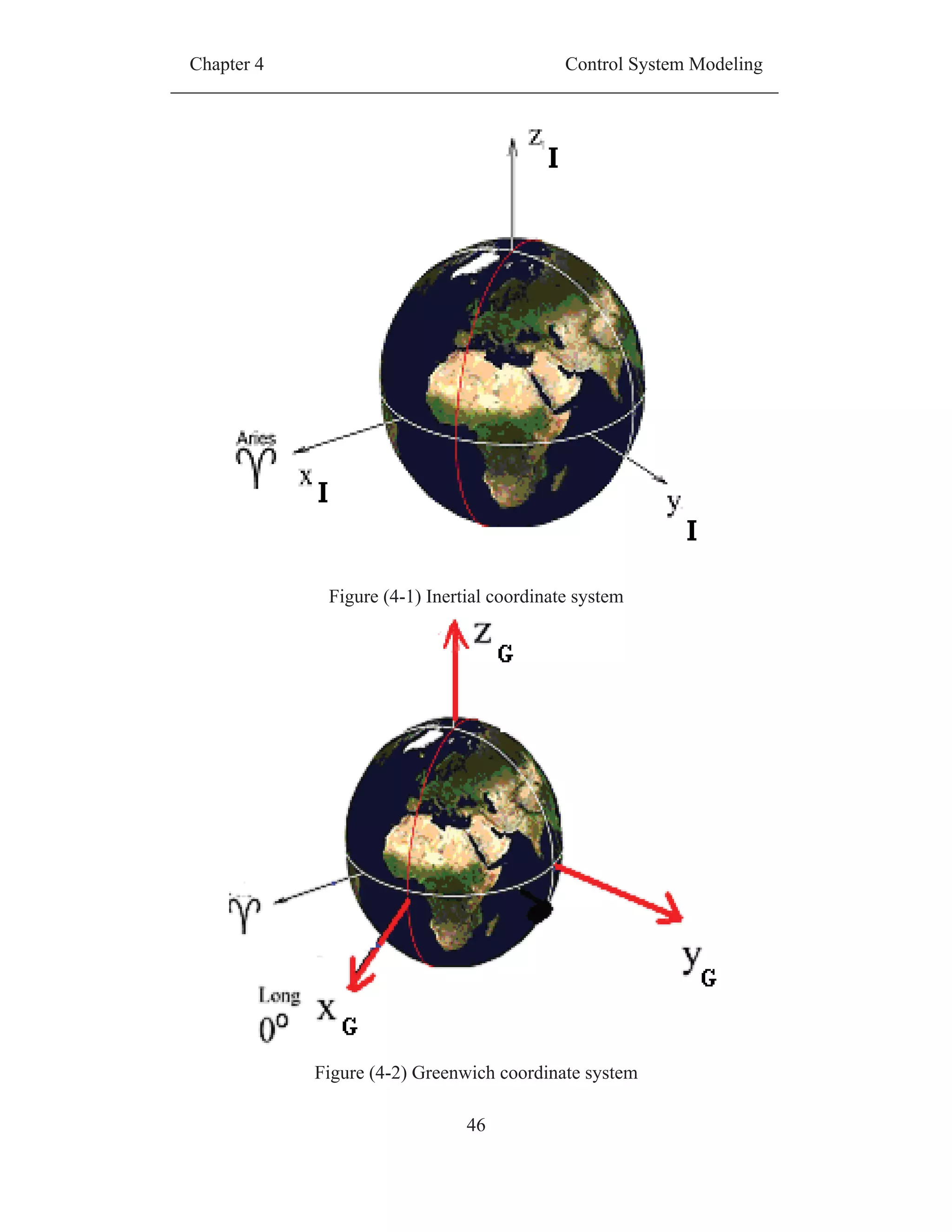
Figure (4-1) Inertial coordinate system............................................................. 46
Figure (4-2) Greenwich coordinate system....................................................... 46
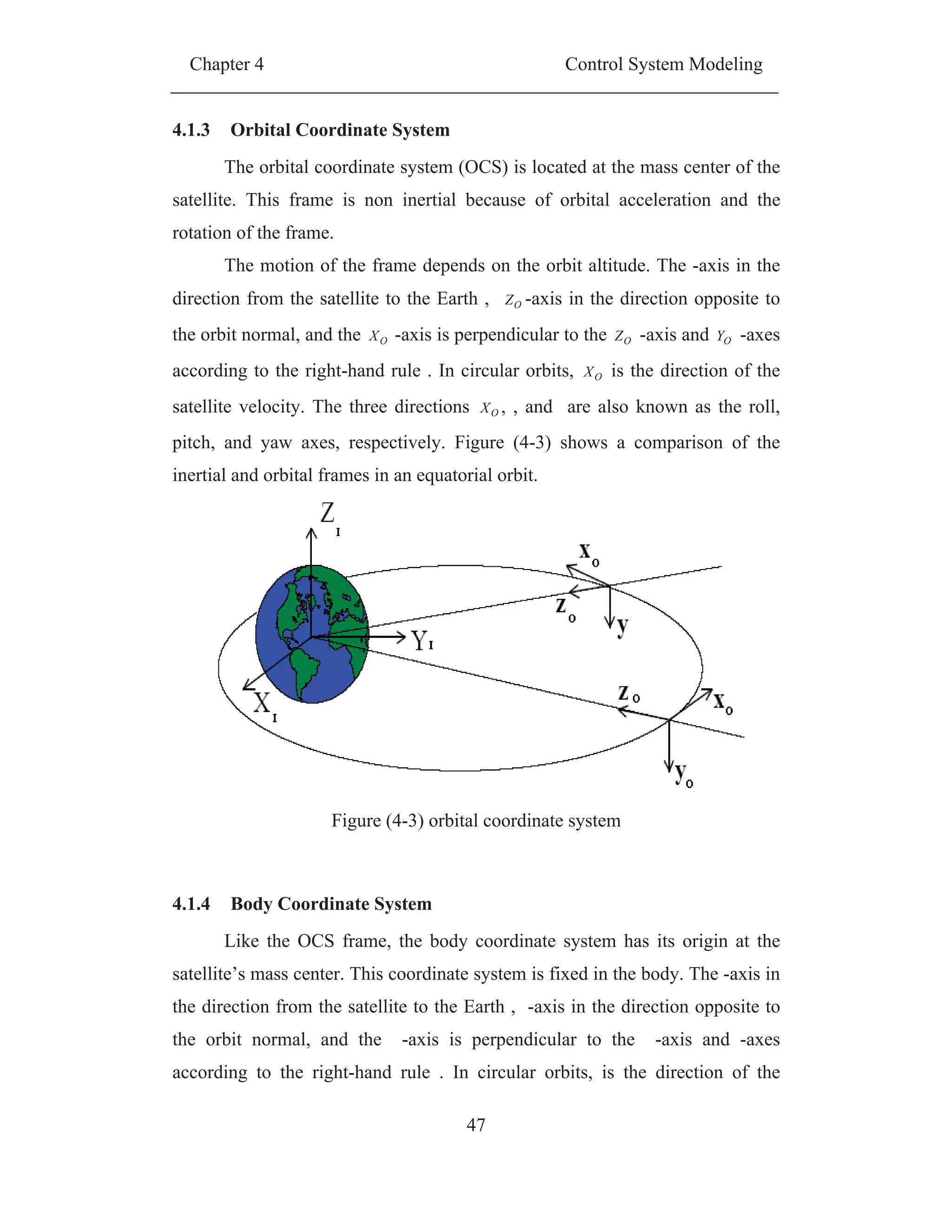
Figure (4-3) orbital coordinate system.............................................................. 47
Figure (4-4) Body coordinate system................................................................ 48
Figure (4-5) device coordinate system.............................................................. 49
Figure (4-6) Angular motion of rigid body....................................................... 50
Figure (4-7) plane showing regions of stability and instability; adapted
from[12] ............................................................................................................ 66
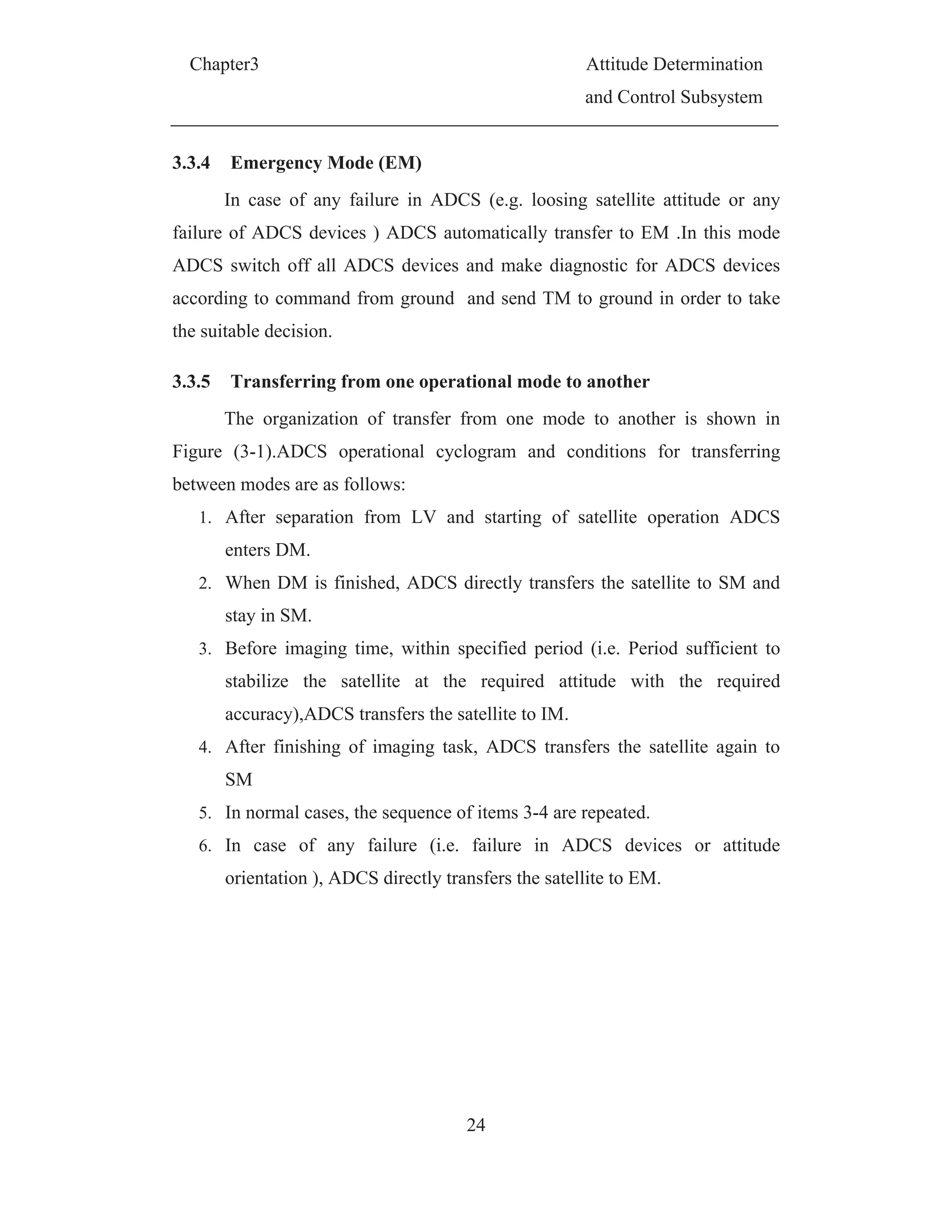
Figure (5-1) ADCS functional diagram ............................................................ 71
Figure (5-2) Magnetic Torque Direction .......................................................... 72
Figure (5-3) Magnetic Control Torques[23] ..................................................... 73
Figure (5-4)Control torque is always perpendicular to the geomagnetic field
vector................................................................................................................. 74
Figure (5-5) Function diagram of velocity suppression using velocity feed
back algorithm.................................................................................................. 75
Figure (5-6 ) Block diagram of velocity suppression using B-dot technique
No1.................................................................................................................... 82
Figure (5-7 )Block diagram of velocity suppression using B-dot technique No2
........................................................................................................................... 83
Figure (5-8) Bock diagram of velocity suppression using B-dot technique No3
........................................................................................................................... 84
Figure (5-9) Cyclogram of angular velocity suppression algorithm................. 86
Figure (5-10) Satellite angular velocity suppression using angular velocity
feedback ............................................................................................................ 87
Figure (5-11) satellite energy during angular suppression using angular velocity
feedback ............................................................................................................ 87
Figure (5-12) required dipole moment to suppress the satellite angular velocity
using angular velocity feedback........................................................................ 88
Figure (5-13) Satellite angular velocity suppression ....................................... 89
Figure (5-14) satellite energy during angular suppression ............................... 90
31](https://image.slidesharecdn.com/spacecraftattitudemagneticcontroller-150428041306-conversion-gate02/75/Spacecraft-attitude-magnetic-controller-12-2048.jpg)
![XIX
Quaternion Describes The Orientation of BCS With Respect
To OCS
0 Scalar Part of Quaternion
Vector Part of Quaternion
Y The Instantaneous Angular Velocity of The Satellite In
Quaternion Form
F Input Matrix For Control
U Vector of Input Control Torque
X State Vector
L Dipole Moment
m Mass
f Force
Me Earth Mass
G The Universal Gravitational Constant
e Earth Rotation Velocity
KinE Kinetic Energy
ggE Potential Energy Associated With The Gravity Gradient
gyroE Potential Energy Due To The Revolution of The Satellite
About The Earth
totE Total Energy
V Lyapunov Candidate Function
Way Angel That Describe The Rotation About Z Axis
Roll Angel That Describe The Rotation About X Axis
Pitch Angel That Describe The Rotation About Y Axis
m
kR Rotation Matrix From k Coordinate System To m Coordinate
System
[R] Direction Cosine Matrix
Quaternion Multiplication
The Angle Between The Line of Aries And Greenwich Line](https://image.slidesharecdn.com/spacecraftattitudemagneticcontroller-150428041306-conversion-gate02/75/Spacecraft-attitude-magnetic-controller-19-2048.jpg)
![Chapter2 Space Segment Overview
5
CHAPTER (2)
SPACE SEGMENT OVERVIEW
2.1 Space System Composition
The block diagram of a space system is shown in Figure (2-1). Space
system can be broken down into three main physical parts; the space segment,
the launch segment, and ground segment. The space segment may be a single
satellite or a constellation of satellites. The satellite contains the payloads that
will accomplish the main mission, as well as the satellite bus that provides the
supporting services for operation of the payload. The launch segment is the
launch vehicle which injects the satellites into its orbit. The ground segment
consists of gateways where the commands are up linked to satellite and data
(i.e. health of satellite and payload data) is down linked from satellites as well
as processing and distribution facilities to put the raw data in the appropriate
form and location for users.[1]
Figure (2-1) Space System
Space System
Space
Segment
Launch
Segment
Ground
Segment](https://image.slidesharecdn.com/spacecraftattitudemagneticcontroller-150428041306-conversion-gate02/75/Spacecraft-attitude-magnetic-controller-24-2048.jpg)
![Chapter2 Space Segment Overview
6
2.2 Satellite Architecture
In general, space segment consists of the satellite; with its main two
parts, the payload and the satellite bus. The satellite bus comprises the other
supporting subsystems whose functions needed to allow the satellite to perform
its mission. Examples of those subsystems are attitude and orbit control, power
generation and data handling. The Payload Module houses the payload sensors,
the facilities needed for data handling and interfaces with satellite subsystems
[2].
2.2.1 Satellite Payload
The payload is dependent upon the mission of the satellite, and is
typically regarded as the part of the satellite "that pays the bills". Typical
payloads are listed below.
2.2.1.1 Communication
Communication satellites provide broadcast (i.e. DirecTV) or point-to-
point (i.e. Iridium) communication services to users around the globe, as well
as data and voice relay between satellite in orbit and controllers on the ground
(i.e. TDRSS). Broadcast missions typically have a set region on the Earth, to
which they are broadcasting, and typically utilization geostationary orbits and a
single satellite to cover a single region, or four satellites in GEO to provide
worldwide broadcast coverage, see Figure (2-2). Point-to-point missions are
typically accomplished with either one or several GEO satellites (like the
broadcast mission).Communication missions that relay data between space and
the Earth typically use GEO satellites.
2.2.1.2 Positioning and Navigation
Positioning and navigation (POS/NAV) missions typically provide near
global coverage and use triangulation as a strategy to provide the POS/NAV
service. Thus, multiple satellites need to be in view of a ground receiver at any
point in time, leading architects to use MEO orbits. Currently, the U.S. fields](https://image.slidesharecdn.com/spacecraftattitudemagneticcontroller-150428041306-conversion-gate02/75/Spacecraft-attitude-magnetic-controller-25-2048.jpg)
![Chapter2 Space Segment Overview
8
All the weather satellites are placed into either of the two types of orbits
around the Earth, namely the polar sun-synchronous low Earth orbit and the
geostationary orbit (GEO) Figure (2-4). Polar orbit weather satellites, due to
their low altitudes, have better spatial resolution as compared to the GEO
satellites Hence they help in a detailed observation of the weather features like
the cloud formation, wind direction, etc. However, these satellites have a
poorer temporal resolution, visiting a particular location only one to four times
a day. Hence, only a few weather satellite systems have satellites in these
orbits. Most weather satellites employ a geostationary orbit as it offers better
temporal resolution as compared to that provided by the polar satellites.
Geostationary weather satellites are the basis of the weather forecasts that are
seen on television [3]
Figure (2-4) Weather Satellites in Geostationary orbit
2.2.1.4 Remote Sensing
Remote sensing satellite is used for acquiring information about the
Earth's surface by sensing reflected or emitted energy by the Earth's surface
with the help of sensors on board the satellite. Based on the source of radiation,
remote sensing can be classified to passive and active.
Passive remote sensing refers to the detection of reflected solar
radiation by the objects on the Earth or the detection of thermal or microwave
radiation emitted by them. The most common passive sensors are imaging
sensors include multi-spectral and panoramic cameras .Camera systems are](https://image.slidesharecdn.com/spacecraftattitudemagneticcontroller-150428041306-conversion-gate02/75/Spacecraft-attitude-magnetic-controller-27-2048.jpg)
![Chapter2 Space Segment Overview
10
2.2.2.1 The Structural Subsystem
The structural subsystem carries, supports, and mechanically aligns the
satellite equipment. It also cages and protects folded components during boost
and deploys them in orbit. The main load-carrying structure or primary
structure is sized by either the strength needed to carry the satellite mass
through launch accelerations and transient events during Launch or stiffness
needed to avoid dynamic interaction between the satellite and the launch
vehicle structures. Secondary structure, which consists of deployable and
supports for components is designed for compact packaging and convenience
of assembly. [4]
2.2.2.2 Attitude Determination and Control Subsystem
The attitude determination and control subsystem measures and controls
the satellite's angular orientation (pointing direction).The simplest satellite are
either uncontrolled or achieve control by passive methods such as spinning or
interacting with the Earth's magnetic or gravity fields. These may or may not
use sensors to measure the attitude or position. More complex systems employ
controllers to process the satellite attitude information obtained from sensors
and actuators torquers to control attitude, velocity, or angular momentum. SC
may have several bodies or appendages, such as solar array or communication
antennas, that required certain direction pointing. The complexity of the
attitude control subsystem depends on the number of body axes and appendage
to be controlled, control accuracy, and speed of response, maneuvering
requirements and the disturbance environment. [4]
2.2.2.3 Propulsion Subsystem
Propulsion subsystem is used to change orbital parameters in order to
transfer from one orbit to another, maintain the satellite in the required orbit all
over its life time. In addition it is also used in attitude maneuver and
stabilization against environmental disturbance forces (e.g. drag), correct
satellite angular momentum and satellite attitude control. The equipment in the](https://image.slidesharecdn.com/spacecraftattitudemagneticcontroller-150428041306-conversion-gate02/75/Spacecraft-attitude-magnetic-controller-29-2048.jpg)
![Chapter2 Space Segment Overview
11
propulsion subsystem includes a propellant supply (propellant, tankage,
distribution system, pressurization and propellant controls) [4].
2.2.2.4 Communications Subsystem
The communications subsystem links the satellite with the ground or
other satellite. Information sent to the satellite (i.e. uplink or forward link),
consists of commands and needed data to satellite (i.e. satellite control
commands and new SW version). Information received from the satellite (i.e.
downlink or return link) consists of satellite status telemetry and payload data.
The basic communication subsystem consists of a receiver, a transmitter, and a
wide-angle (hemispheric or omni-directional) antenna. Systems with high data
rates may also use a directional antenna [4].
2.2.2.5 Command and Data Handling Subsystem
The command and data handling subsystem distributes commands to
assigned subsystems. It also stores data from the satellite and payload. For
simpler systems, we combine these functions with the communications
subsystem as a tracking, telemetry, and command subsystem. This arrangement
assumes that distributing commands and formatting telemetry are base upon
extensions of communications modulation and demodulation. In its more
general structure, it comprises a central processor (computer), data buses,
remote interface units, and data storage units to implement its functions. It may
also handle sequenced or programmed events [4].
2.2.2.6 Power System
Satellites must have a continuous source of electrical power-24 hours a
day, 365 days a year. The two most common power sources are high
performance batteries and solar cells. Solar cells are an excellent power source
for satellites. They are lightweight, resilient, and over the years have been
steadily improving their efficiency in converting solar energy into electricity.
There is however, one large problem with using solar energy. If solar energy](https://image.slidesharecdn.com/spacecraftattitudemagneticcontroller-150428041306-conversion-gate02/75/Spacecraft-attitude-magnetic-controller-30-2048.jpg)
![Chapter2 Space Segment Overview
12
were the only source of power for the satellite, the satellite would not operate
during eclipse period. To solve this problem, batteries are used as a
supplemental on-board energy source. Initially, Nickel-Cadmium batteries were
utilized, but more recently Nickel-Hydrogen batteries have proven to provide
higher power, greater durability, and the important capability of being charged
and discharged many times over the lifetime of a satellite mission. [5]
2.2.2.7 The Thermal Subsystem
The thermal subsystem controls the satellite equipment's temperatures.
Normally thermal control is done through either passive or active techniques.
In passive control, It does so by the physical arrangement of equipment, using
thermal insulation and coating. This is done to balance heat from power
dissipation, absorption from the Earth and Sun, and other radiation sources in
the space. Sometimes passive, thermal-balance techniques are not enough. In
this case, active control in the form of electrical heaters, high-capacity heat
conductors, and/or heat pipes, are employed [4].
2.3 Satellite Orbits
After a satellite is separated from launching vehicle, it moves in a path
around the Earth called an orbit. Satellite orbiting Earth due to the balance
between two forces, gravitational force which attracts the satellite towards the
Earth and centrifugal force (due to linear velocity of the satellite in orbit )
which causes repulsion of the satellite out from Earth [3],see Figure (2-6.)
During satellite mission design, the orbit is chosen which is appropriate to its
mission. So, a satellite that is in a very high orbit will not be able to see objects
on Earth as many details as orbits that are lower, and closer to the Earth's
surface. Similarly, the satellite velocity in orbit, the areas observed by the
satellite, and the frequency with which the satellite passes over the same
portions of the Earth are all important factors in satellite orbit selection.
Essentially, there are six orbital parameter called classical Keplerian orbital
elements define the orbit as shown in Figure (2-8) [5].](https://image.slidesharecdn.com/spacecraftattitudemagneticcontroller-150428041306-conversion-gate02/75/Spacecraft-attitude-magnetic-controller-31-2048.jpg)
![Chapter2 Space Segment Overview
13
Figure (2-6) Gravitational force and the centrifugal force acting on bodies
orbiting Earth
1. Semi-major axis. a This is a geometrical parameter of the elliptical
orbit. It can, however, be computed from known values of apogee and
perigee distances as [3], for definition of apogee and perigee see Figure
(2-7).
2
perigeeapogee
a (2.1)
2. Eccentricity.e The orbit eccentricity is the ratio of the distance between
the centre of the ellipse and its focus to the semi-major axis of the
ellipse [3] see Figure (2-7).
3. Right ascension of the ascending node . it tells about the orientation of
the line of nodes, which is the line joining the ascending and descending
-nodes, with respect to the direction of the vernal equinox [3] See
Figure (2-8).
Vernal equinox is the line that intersects the Earth's equatorial plane and
the Earth's orbital plane, which passes through the centre of the Earth with
respect to the direction of the sun on 21 March [3].
4. Inclination i . is the angle that the normal to the orbital plane of the
satellite makes with the normal to the equatorial plane [3] , Figure (2-9).
5. Argument of the perigee W. This parameter defines the location of the
major axis of the satellite orbit. It is measured as the angle between
the line joining the perigee and the focus of the ellipse and the line of](https://image.slidesharecdn.com/spacecraftattitudemagneticcontroller-150428041306-conversion-gate02/75/Spacecraft-attitude-magnetic-controller-32-2048.jpg)
![Chapter2 Space Segment Overview
14
nodes in the same direction as that of the satellite orbit [3], see Figure
(2-9).
6. True anomaly of the satellite fo. This parameter is used to indicate the
position of the satellite in its orbit. It is defined as the angle, between the
line joining the perigee and the centre of the Earth with the line joining
the satellite and the centre of the Earth [3], see Figure (2-9)
Orbits can be classified according to different criteria [3], such as
1. According to orbit Altitude
o Low Earth Orbit (LEO): orbit altitude ranging in altitude from
200–1000 km
o Medium Earth Orbit (MEO): orbit altitude ranging from 1000 km
to just below geosynchronous orbit at 35786 km.
o High Earth Orbit (HEO): orbit altitude above 35786 km.
(a) (b)
Figure (2-7) apogee ,perigee of the orbit and semi-major axis
Figure (2-8) Right ascension of the ascending node](https://image.slidesharecdn.com/spacecraftattitudemagneticcontroller-150428041306-conversion-gate02/75/Spacecraft-attitude-magnetic-controller-33-2048.jpg)
![Chapter2 Space Segment Overview
16
2.3.1 Special Orbits
An important consideration in space mission design is determining the
type of Earth Orbit that best suits the design goals and purpose of the mission.
A brief description for the special orbits which frequently used such as; low
Earth orbit, medium Earth orbit, geostationary orbit, polar orbit, Sun-
synchronous orbit and Molniya orbit, is presented.
2.3.1.1 Low Earth Orbit (LEO)
Orbiting the Earth at roughly 200-1000 Km altitude [6]: Almost 90
percent of all satellites in orbit are in LEO [6]. LEO is often utilized because of
the low launch requirements that are needed to place a satellite into orbit. LEO
satellites orbit the Earth in roughly 90 minute periods. This means that they are
fast moving, and sophisticated ground equipment must be used to track the
satellite, LEO is used for such missions as flight tests, Earth observations,
astronomical observations, space stations and scientific experiments [8], [6].
Figure (2-10) LEO, MEO and GEO
2.3.1.2 Medium Earth Orbit (MEO)
MEO sometimes called Intermediate Circular Orbit (ICO), is the region
of space around the Earth above low Earth orbit (1,000 kilometers) and below
geostationary orbit (35,786 Km).The most common use for satellites in this](https://image.slidesharecdn.com/spacecraftattitudemagneticcontroller-150428041306-conversion-gate02/75/Spacecraft-attitude-magnetic-controller-35-2048.jpg)
![Chapter2 Space Segment Overview
17
region is for navigation, such as the GPS (20,200 Km) and Galileo
(23,222 Km) constellations. Communications satellites that cover the North and
South Pole are also put in MEO [6]. The orbital periods of MEO satellites
range from about 2 o 12 hours. Telstar, one of the first and most famous
experimental satellites, orbited in MEO [9]
2.3.1.3 Geostationary/Geosynchronous Earth Orbit (GEO)
Satellite in geostationary orbit appears to remain in the same spot in the
sky all the time. Really, it is simply traveling at exactly the same speed as the
Earth is rotating below it, but it looks like it is staying still regardless of the
direction in which it travels, east or west. A satellite in geostationary orbit is
very high up, at 35,850 km above the Earth. Geostationary orbits, therefore, are
also known as high orbits; GEO is used for communications satellite
Figure (2-11) GEO satellites appear stationary with respect to a point on Earth
2.3.1.4 Polar Earth Orbit
For full global coverage of the Earth, a ground track would have to
cover latitudes up to 90o
. The only orbit that satisfies this condition has an
inclination of 90°. These types of orbits are referred to as polar orbits. Polar
orbits are used extensively for the purpose of global observations.](https://image.slidesharecdn.com/spacecraftattitudemagneticcontroller-150428041306-conversion-gate02/75/Spacecraft-attitude-magnetic-controller-36-2048.jpg)
![Chapter2 Space Segment Overview
18
2.3.1.5 Sun Synchronous Orbits (SSO)
A Sun-synchronous orbit (SSO) is a nearly polar orbit where the
ascending node precesses at 360 degrees per year or 0.9856 degrees per day.
SSO orbital plane has a fixed orientation with respect to the_Earth-sun
direction and the angle between the orbital plane and the Earth-sun line remains
constant throughout the year as shown in Figure (2-12), so this type of orbit
assures that the local solar time (LST) at the ascending node is nearly constant
throughout the life of the mission. Satellites in sun-synchronous orbits are
particularly suited to applications like passive remote sensing, meteorological
and atmospheric studies,[6].
Figure (2-12) Sun synchronous orbit
2.3.1.6 Molniya Orbit
Highly eccentric, inclined and elliptical orbits are used to cover higher
latitudes, which are otherwise not covered by geostationary orbits. A practical
example of this type of orbit is the Molniya orbit. It is a widely used satellite
orbit, used by Russia and other countries of the former Soviet Union to provide
communication services. Typical eccentricity and orbit inclination figures for
the Molniya orbit are 0.75 and 65° respectively. The apogee and perigee points
are about 40000 km and 400 km respectively from the surface of the Earth. It
has a 12-hour orbit and a satellite in this orbit remains near apogee for](https://image.slidesharecdn.com/spacecraftattitudemagneticcontroller-150428041306-conversion-gate02/75/Spacecraft-attitude-magnetic-controller-37-2048.jpg)
![Chapter2 Space Segment Overview
19
approximately 11 hours per orbit [4] before diving down to a low-level perigee.
Usually, three satellites at different phases of the same Molniya orbit are
capable of providing an uninterrupted service.
Figure (2-13) Molniya orbit](https://image.slidesharecdn.com/spacecraftattitudemagneticcontroller-150428041306-conversion-gate02/75/Spacecraft-attitude-magnetic-controller-38-2048.jpg)
![Chapter3 Attitude Determination
and Control Subsystem
26
3.4.1.1 Earth’s Horizon sensor
For near-Earth satellites the Earth covers a large proportion of the sphere
of view and presents a large area for detection. The presence of the Earth alone
does not provide a satisfactory attitude reference hence the detection of the
Earth’s horizon is widely used.
Horizon sensor is infrared device that detect the contrast between the
cold of deep space and the heat of the Earth’s see Figure (3-2). Horizon sensors
can provide pitch and roll attitude knowledge for Earth-pointing satellite. For
the better accuracy in low Earth orbit (LEO), it is necessary to correct the data
for the Earth oblateness and seasonal changes in the apparent horizon
[10].Earth’s Horizon sensor is used in AEROS-I,-2, MAGSAT, SEASAT [15].
Figure (3-2) principle of Earth horizon sensor
3.4.1.2 Sun sensor
Sun sensor is widely used with satellite mission due to the special
features of sun as a space object. One of these features is the brightness of the
sun, which makes it easy to be distinguished among other solar and stellar
objects. also the Sun-Earth distance makes it appear as nearly a point source
(0.25 º). Those factors urge ADCS designer to rely upon sun sensors in high
pointing accuracy missions.](https://image.slidesharecdn.com/spacecraftattitudemagneticcontroller-150428041306-conversion-gate02/75/Spacecraft-attitude-magnetic-controller-45-2048.jpg)
![Chapter3 Attitude Determination
and Control Subsystem
27
Sun sensor measures one or two angles between their mounting base
and incident sunlight. Categories of sensors are ranging from just sun presence
detector, which detects the existence of sun, rather accurate analogue sensor
measuring sun incidence angle, up to high accuracy digital instrument, which
measure the sun direction to accuracy down to one arc-minute. Typical digital
sun sensor is shown Figure (3-3).
Sun sensor is accurate and reliable, but require direct line of sight to the
sun. Since most low-Earth orbits include eclipse periods, the attitude
determination system should provide some way of handling the regular loss of
Sun vision. Sun sensor is used in AEROS-1,2 , GEOS-3, MAGSAT, SAGE,
SEASAT [15].
Figure (3-3) Sun sensors
3.4.1.3 Star mapper
Star mapper provides the most accurate absolute pointing information
possible for a satellite attitude. It contains Charged-Coupled Device (CCD)
sensors or Active Pixel Sensors (APS) which provides a relatively inexpensive
way to image the sky. It extracts information about satellite attitude by
mapping the obtained stars image with the stored stars pattern catalog. Any](https://image.slidesharecdn.com/spacecraftattitudemagneticcontroller-150428041306-conversion-gate02/75/Spacecraft-attitude-magnetic-controller-46-2048.jpg)
![C
orie
corr
thre
suff
fram
velo
sen
imp
iden
MA
3.4.
dire
requ
attit
Nav
mag
pos
Chapter3
entation of
responding
ee stars on
ficient to d
me of refe
ocities of t
sor.
The a
possible wi
ntification.
AGSAT [15
.1.4 Magn
Magne
ection and
uire comp
tude deter
vigational
gnetic fiel
sition. Com
f satellite w
g star patte
n the senso
determine
erence. Th
the satellit
accuracy a
ithout high
. Star sen
5].
netometers
etometers a
magnitud
plex softw
rmination
informatio
d to app
mparison be
will detecte
ern as show
or, along w
the attitud
he star cam
te as this c
Figu
and autono
h-speed mi
nsor is us
s
are simple
e of the E
ware for in
as comp
on are use
proximate
etween me
28
d as a shift
wn in Figu
with their lo
de of the c
mera is ge
causes a sm
ure (3-4) S
omy provi
icroprocess
sed in AT
, lightweig
Earth’s mag
nterpretatio
pared to
ed with a
the field d
easured and
A
a
ft between t
ure (3-4).
ocations in
camera wi
enerally se
mearing of
Start sensor
ided by a
sors for im
TS-6, Egy
ght sensors
gnetic fiel
on and pr
horizon, s
a computer
direction a
d calculate
Attitude De
and Contro
the imaged
The locati
n inertial c
ith respect
ensitive to
f the star i
r
star cam
mage proce
yptsat-1, L
s that mea
d. They ar
rovide rela
sun, and
r model o
at the sate
ed earth ma
eterminatio
l Subsystem
d stars and
ons of at l
coordinates
to an ine
large ang
images on
mera would
essing and
LANDSAT
asure both
re reliable
atively co
star sens
of the Ear
ellite’s cur
agnetic fiel
on
m
d the
least
s are
ertial
gular
n the
d be
star
T-D·,
the
but
oarse
sors.
rth’s
rrent
ld is](https://image.slidesharecdn.com/spacecraftattitudemagneticcontroller-150428041306-conversion-gate02/75/Spacecraft-attitude-magnetic-controller-47-2048.jpg)
![Chapter3 Attitude Determination
and Control Subsystem
29
used to provide information about satellite orientation. Employing estimation
techniques such as Kalman filter, allows magnetometer to work as standalone
device for attitude determination [11]. The Earth’s magnetic field also varies
with time and can't be calculated precisely, so a magnetometer is often used
with another sensor such as a sun, horizon or star sensor or a gyroscope in
order to improve the accuracy. Magnetometer is used in AEROS-1, Egyptsat1,
GEOS-3, SEASA [15].
Figure (3-5) flux-gate magnetometer
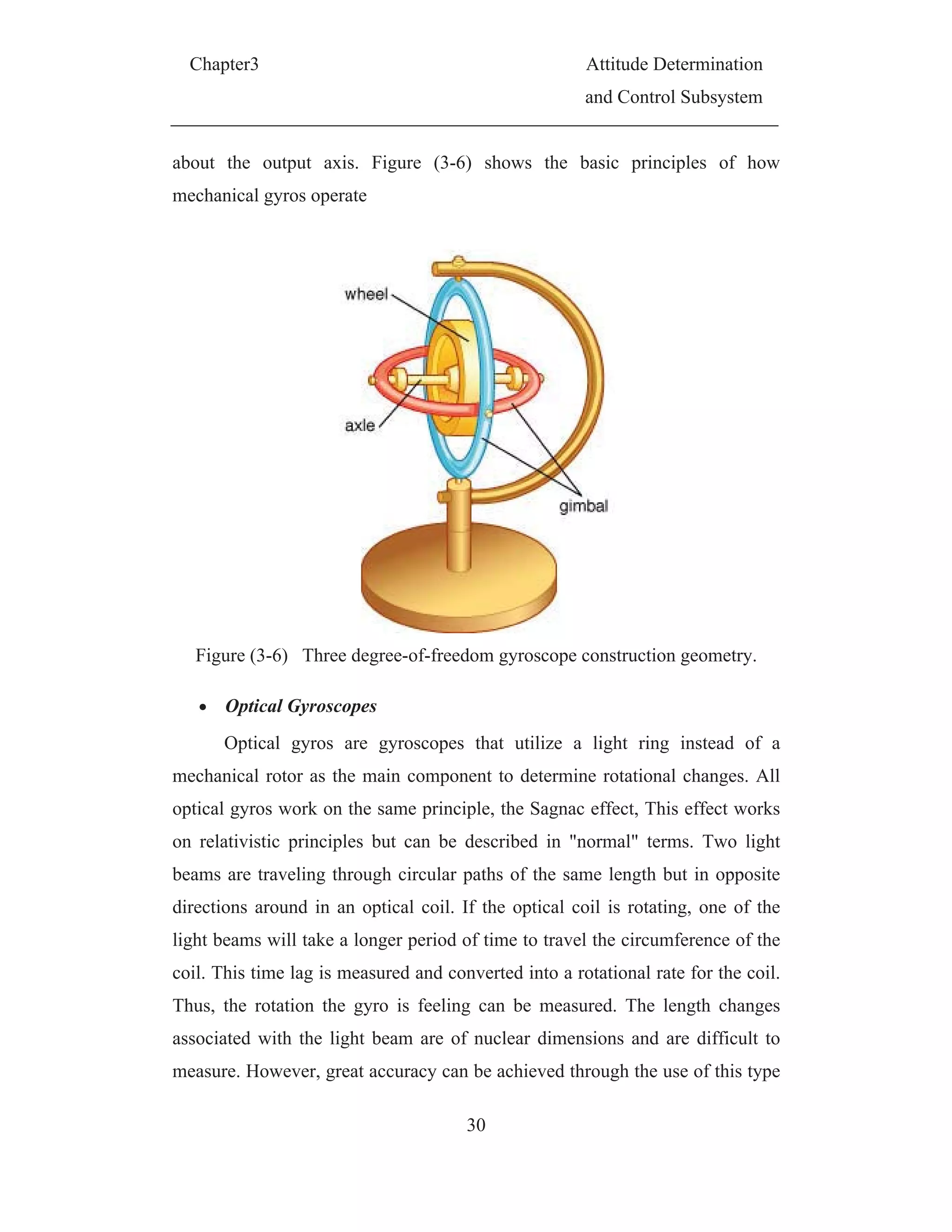
3.4.1.5 Inertial Sensor or Gyro
By definition, a gyroscope, is any instrument, which uses a rapidly
spinning mass to sense and respond to changes in the inertial orientation of its
spin axis. There are types of attitude sensing gyros: mechanical and optical
gyro. These sensors measure satellite orientation change.
Mechanical Gyroscopes
The angular momentum of a gyro, in the absence of an external torque,
remains constant in magnitude and direction in space. Therefore, any rotation
of the satellite about the gyro's input axis results in a precession of the gimbal](https://image.slidesharecdn.com/spacecraftattitudemagneticcontroller-150428041306-conversion-gate02/75/Spacecraft-attitude-magnetic-controller-48-2048.jpg)
![Chapter3 Attitude Determination
and Control Subsystem
31
of gyroscope. The most common devices of this type is the Ring Laser Gyro
(RLG) and Fiber Optic Gyros (FOG) .Gyros are used in ATS-6,
Egyptsat1,LANDSAT-D·, MAGSAT [15].
Figure (3-7) The QRS11Pro gyro used on Rømer
Typical values for accuracy of ADCS sensors are shown in the
following table
Table 3-1 Ranges of ADCS sensors accuracy
Sensor Accuracy
Earth’s Horizon sensor
0.05 deg. (GEO)
0.1 deg. (LEO)
Sun sensor 0.01 deg.
Star mapper 2 arc. sec.
Magnetometers
1.0 deg. (5,000 Km altitude)
5.0 deg. (200 Km altitude)
Gyro 0.001 deg./hr](https://image.slidesharecdn.com/spacecraftattitudemagneticcontroller-150428041306-conversion-gate02/75/Spacecraft-attitude-magnetic-controller-50-2048.jpg)
![Chapter3 Attitude Determination
and Control Subsystem
33
Figure (3-8) The TELDIX Momentum and Reaction
Momentum and reaction wheels have the advantage of providing quick
and accurate attitude control. Also, they can be used at any altitude. Their
disadvantage is that they can be costly, massive, and require large amounts of
power. However, wheels may saturate since the RW is a motor that has
maximum speed, since the angular momentum that can be stored in the wheels
is limited, so a secondary control system is used to prevent the stored
momentum from reaching the maximum limit. The secondary control system
can be thrusters system or magnetorquers. Momentum and reaction wheels are
used in Egyptsat1, FLTSATCOM, MAGSAT and SEASAT [15].
3.4.2.2 Magnetic actuators
Magnetic actuators enforce a torque on the satellite by generating a
dipole moment, which interacts with the Earth's magnetic field. Generally,
there are two types of magnetic actuators, torque coils and magnetic rods or
magnetorqure.
1. Torque Coils](https://image.slidesharecdn.com/spacecraftattitudemagneticcontroller-150428041306-conversion-gate02/75/Spacecraft-attitude-magnetic-controller-52-2048.jpg)
![Chapter3 Attitude Determination
and Control Subsystem
35
Hence, generating specified dipole moment from magnetic rod needs
current much lower than that needed to magnetic coil. However, the weight of
magnetic rod increases drastically because of the metal core in the rods.
Another inconvenience of the torque rods is the hysteresis effect associated
with ferromagnetic core which add nonlinearity to the control loop. Advantages
and disadvantages of using magnetic actuator will be discussed in details in
CHAPTER (5). Magnetic actuators are used with Egyptsat1, MAGSAT,
TIROS-IX, LANDSAT-D and AEROS-1, 2[15].
Figure (3-10) Torque rods
3.4.2.3 Thruster
Thruster works on the principle of Newton's third law, according to
which "for every action, there is an equal and opposite reaction". Referring to
this principle, if gas is propelled out of a nozzle, the satellite will accelerate in
opposite direction. However, if the nozzles are not pointed directly away from
the center of mass this will lead to cause rotational of satellite as well. In
addition, if two thrusters in opposite direction but not co-lined rotation only
will be generated. The source of the used gas defines the type of thruster .
Cold gass thrusters use high pressure storage tank. Hot gas thrusters use the
combustion of either monopropellant or bipropellant.
Six thrusters are needed to be mounted in pairs to generate the torque
needed for three-axis control. Thruster as actuator is highly accurate and](https://image.slidesharecdn.com/spacecraftattitudemagneticcontroller-150428041306-conversion-gate02/75/Spacecraft-attitude-magnetic-controller-54-2048.jpg)
![Chapter3 Attitude Determination
and Control Subsystem
36
generate higher torque than RW and magnetic rods. On the other hand, the
structure used with the thrusters is large and heavy. Besides, run out of either
gas or propellant will lead to stop functioning of thrusters. Thrusters are used in
ATS-3,6 , FLTSATCOM, GOES-I and SKYNET[15].
Figure (3-11) Torque generated thruster mounted to satellite
3.5 Disturbance Environment
In an Earth orbit, the space environment imposes several external
torques that the ADCS system must tolerate. According to orbit altitude, three
or four sources of disturbing torques are affecting the space craft[4]. These
torques are; gravity gradient, magnetic field effect, solar radiation pressure, and
aerodynamic forces. Those disturbances are affected by the satellite’s
geometry, orientation, and mass properties in addition to satellite orbital
altitude.
3.5.1 Gravity Gradient Disturbance
Any object with nonzero dimensions orbiting Earth will be subjected to
a “gravity-gradient” torque. In short, the portions of the satellite that are closer
to the Earth are subjected to a slightly larger force than those parts farther away
[7]. This creates a force imbalance that has a tendency to orient the satellite
towards the center of Earth in order to compensate this imbalance. According
to [15] the gravity gradient torque can be determined by equation (3.3) . The
worst case torque arises at
o
90](https://image.slidesharecdn.com/spacecraftattitudemagneticcontroller-150428041306-conversion-gate02/75/Spacecraft-attitude-magnetic-controller-55-2048.jpg)
![Chapter3 Attitude Determination
and Control Subsystem
37
)2sin(
2
3
3 iiZZgg JJ
R
T (3.3)
Where,
Tgg: is the resulting gravitational torque [Nm]
μ: is the gravitational constant of the earth [m³/s²] (μ = 3.896*1014
m³/s²)
Jii :is the moment of inertia tensor for the satellite in i axis.(in body
coordinate system) [kgm²] (i=x,y,z)
Is the maximum deviation angel from the local vertical [rad]
R: is the distance between satellite center of mass and earth center of
mass [km]
The previous formula for calculation of gravity gradient is used to give
course estimation of gravity gradient disturbance torque but an accurate
formula given in (4.28) is used in calculation of satellite mathematical model
3.5.2 Magnetic Field Disturbance
Magnetic field torques are generated by interactions between the
satellite magnetic dipole and the Earth’s magnetic field. This satellite magnetic
dipole is the summation of two components; first component is the induced
magnetic dipole, which is caused by current running through the satellite
wiring harness and second component is the residual dipole moment, which is
caused due to magnetic properties of the satellite components. The satellite
magnetic dipole exhibits transient and periodic fluctuations due to power
switching between different subsystems. These effects can be minimized by
proper placement of the wiring harness. The magnetic torque is calculated by
following formula
BDTm (3.4)
Where
D = the vector of total satellite magnetic dipole.
B = local geomagnetic field vector.](https://image.slidesharecdn.com/spacecraftattitudemagneticcontroller-150428041306-conversion-gate02/75/Spacecraft-attitude-magnetic-controller-56-2048.jpg)
![Chapter3 Attitude Determination
and Control Subsystem
38
In the worst case, the vectors are perpendicular to each other and the
cross product turns into a product of scalar values.
3.5.3 Solar Radiation Pressure Disturbance
Solar radiation pressure is a result of the transfer of momentum from
photons of light to the surface of the satellite. The result of this pressure across
the satellite surface is a force that acts through the center of pressure, psc , of the
satellite. In most cases, the center of pressure is not co-onside with the center of
mass of the satellite, thus a torque will be generated around the center of mass
cm see Figure (3-12). For Earth-orbiting satellite, where the distance from the
satellite to the Earth is small compared to the Earth-Sun distance, the mean
solar flux acting on the satellite is considered a constant (regardless of orbital
radius or position).
The solar radiation torque is calculated using the following equation [4] .
)()cos()1( gpssSp cciqA
c
So
T
(3.5)
Where
So is solar constant [W/m²] = 1428 W/m² (max)
c is speed of light [m/s] = 3*108
m/s
A is the cross sectional area subjected to solar radiation pressure [m²]
q is reflectance factor (0: perfectly absorbing, 1: perfectly reflecting)
si is the angle of sun light incidence [rad]
cps is the center of pressure [m]
cg is the center of gravity [m]
Referring to the previous assumptions, the solar pressure disturbance
torque is the only one that is not dependent of the orbit altitude. However, it is
dependent of the sun incidence angle i. The worst case torque arises at i = 0°.](https://image.slidesharecdn.com/spacecraftattitudemagneticcontroller-150428041306-conversion-gate02/75/Spacecraft-attitude-magnetic-controller-57-2048.jpg)
![C
3.5.
as
esp
torq
cha
to t
sign
effe
adT
Wh
is
cD i
A is
vc i
cps
cg i
3.6
com
Chapter3
.4 Aerod
Aerody
shown in
ecially at l
que is alm
anging of s
the aerodyn
nificantly
ects is calcu
Dc
2
1
here
s the densit
is the coeff
s the cross
s the orbita
is the cent
is the cente
Attitu
There
mpensation
dynamic D
ynamic torq
Figure (3
low altitud
ost negligi
ome param
namic drag
with solar
ulated by (
C cvA
2
ty [kg/m³]
ficient of d
sectional a
al velocity
ter of press
er of gravit
Fig
ude Contr
are differe
n and to ma
Disturbanc
ques are du
3-12. Aero
des (less th
ible. These
meters, such
g during ti
r activity.
(3.6) .
gpa cc
drag
area subjec
[m/s]
sure [m]
ty [m]
gure (3-12)
rol techniq
ent techniq
aintain the
39
ce
ue to atmo
odynamic
an 500). A
e torques i
h as cross
lting. In ad
The gene
cted to atm
Sunlight a
ques
ques to app
required or
A
a
ospheric dr
torques ca
At higher a
is difficult
sectional a
ddition, atm
erated torq
mospheric d
and drag ef
ply contro
rientation .
Attitude De
and Contro
rag acting o
an be qui
ltitudes the
to be calc
area of sate
mospheric
que due to
drag [m²]
ffect
ol torque fo
. For these
eterminatio
l Subsystem
on the sate
ite signific
e aerodyna
culate beca
ellite subje
density va
o aerodyna
(3.6)
for disturba
purposes,
on
m
ellite
cant,
amic
ause
cted
aries
amic
ance
two](https://image.slidesharecdn.com/spacecraftattitudemagneticcontroller-150428041306-conversion-gate02/75/Spacecraft-attitude-magnetic-controller-58-2048.jpg)
![Chapter3 Attitude Determination
and Control Subsystem
40
types of control techniques are often employed , passive and active control
[4][12]. Since Attitude control system, is highly mission dependent, so the
decision to use a passive or an active control technique or a combination of
them depends on mission pointing and stabilization requirements.
3.6.1 Passive Control
For missions with rather coarse orientation requirements, passive control
techniques are used for attitude control. The main advantageous of these
techniques are saving resources concerning both mass and power and the
associated cost. In addition, they provide longer lifetime for the space mission.
However, a poor pointing accuracy is obtained. The most common passive
control techniques are passive magnetic system (i.e. Permanent magnate),
gravity gradient and spin stabilization [4].
3.6.1.1 Passive magnetic
In this method, the concept of magnetic compass is applied, that is, the
satellite is equipped with permanent magnet that will keep the alignment
between certain axis of the satellite with geomagnetic field vector .As a result,
the south pole of the magnet will be drawn towards the magnetic north pole of
the Earth, and vice versa. This will lead to a slight tumbling motion with two
revolutions per orbit and no possibilities of controlling spin around the magnets
axis as shown in Figure (3-13) so continues nadir pointing will not be possible.
Permanent magnet technique is used in AZUR-1 [15].](https://image.slidesharecdn.com/spacecraftattitudemagneticcontroller-150428041306-conversion-gate02/75/Spacecraft-attitude-magnetic-controller-59-2048.jpg)
![Chapter3 Attitude Determination
and Control Subsystem
41
Figure (3-13) passive magnetic control orientation profile.
3.6.1.2 Gravity-gradient stability
Gravity-gradient stability uses the mass characteristics of the satellite to
maintain the nadir pointing towards Earth (as described in 3.5.1). The
magnitude of gravity-gradient torque decreases with the cube of the orbit
radius, and symmetric around the nadir vector, thus not influencing the yaw of
satellite. Therefore, the gravity gradient stability is used in simple satellite in
LEO without yaw orientation requirements [4].
Yet, stability in the gravity gradient case depends upon the the
configuration of the mass characteristics of the space craft. The following
condition is necessary for gravity-gradient stability [12]:
JzzJxxJyy&JzzJxxJyy (3.7)
Where Jii :is the moment of inertia tensor for the satellite in i axis.(in
body coordinate system) (i=x,y,z)](https://image.slidesharecdn.com/spacecraftattitudemagneticcontroller-150428041306-conversion-gate02/75/Spacecraft-attitude-magnetic-controller-60-2048.jpg)
![Chapter3 Attitude Determination
and Control Subsystem
42
As a result, the gravity gradient stability can be achieved by
manipulation of lay out of the satellite's components to grantee the above
mentioned condition (3.7). Other solution is to add a sufficient mass on a
deployed boom to reach the stability condition. This will increase the moment
of inertia in the directions transverse to the boom, and the satellite will be
stable with the mass pointed toward or away from the earth. Gravity gradient
stability is suffering from continuous oscillation about nadir due to lack of
damping. Hence, gravity-gradient stabilization should be supported with
damping system to reduce the small oscillation around the nadir vector.
Gravity-gradient stabilization technique is used in DODGE, GEOS-3, and
RAE-2 [15].
3.6.1.3 Spin stabilization
Spin stabilization technique applies the gyroscopic stability to passively
resist the effect of disturbance torques about the spinning axis. Spin-stabilized
satellites spins about their major or minor axes, so angular momentum vector
remains approximately fixed with respect to inertial space. [15]. Spinning
satellite is classified according to spinning object to single or dual spin. The
stability criteria and the corresponding spinning axis is predicted according to
the following analysis.
3.6.1.3.1. Single Spin
In single spin satellites, the whole satellite spins about the angular
momentum vector as shown in Figure (3-14) This method of stabilization is
simple and has a high reliability. The cost is generally low, and it has a long
system life. However, Spin-stabilized satellite are subject to nutation and
precession, but have a gyroscopic resistance which provides stability about the
transverse axis.
On the other side, spinning satellite will have poor maneuverability.
Beside, it will not be suitable for systems that need to be Earth pointing, such](https://image.slidesharecdn.com/spacecraftattitudemagneticcontroller-150428041306-conversion-gate02/75/Spacecraft-attitude-magnetic-controller-61-2048.jpg)
![Chapter3 Attitude Determination
and Control Subsystem
43
as payload scanners and communication antennas. Single spin stabilization
technique is used in AEROS-I,2, ALOUETIE-I,2and ARIEL-I [15].
Figure (3-14) spin stabilization
3.6.1.3.2. Dual Spin
In satellite with dual spin, a major portion of the satellite is spun, while
the payload section is despun. This technique is favorable because fixed inertial
orientation is possible on the despun portion. This method of stabilization has a
few disadvantages, however. This system is much more complex, which leads
to an increase in cost and a decrease in reliability. In addition, the stability is
sensitive to mass imbalances. Duel spin stabilization technique is used in ANS,
ATS-6, SEASAT and SMM [15].
3.6.2 Active control techniques
For complex mission requirements, satellite requires continues
autonomous control about the three axes during the mission. In general, active
control systems employ momentum exchange wheels, magnetic control
devices, and thrusters. Advantages of these systems are high pointing accuracy,
and a not constrained to inertial pointing like spin stabilization technique.](https://image.slidesharecdn.com/spacecraftattitudemagneticcontroller-150428041306-conversion-gate02/75/Spacecraft-attitude-magnetic-controller-62-2048.jpg)
![Chapter3 Attitude Determination
and Control Subsystem
44
However, the hardware is often expensive, and complicated, leading to a higher
weight and power consumption.
3.6.2.1 Momentum exchange Wheels
Three-axis stabilization through momentum exchange wheels applies
reaction wheels, momentum wheels, and control moment gyros. This is to
provide three axis stabilization. Advantages and disadvantages of this wheel
system are discussed in 3.4.2.1. Three-axis stabilization technique using wheels
is used in Egyptsat1, FLTSATCOM, MAGSAT and SEASAT [15].
3.6.2.2 Magnetic actuators
Magnetic actuators devices use the interaction of the satellite magnetic
dipole moment and the Earth’s magnetic field to provide a control torque.
Magnetic control torques work better in low Earth orbits than higher orbits,
such as geostationary, because as the distance from the Earth increases, the
geomagnetic strength decreases. Advantage and disadvantage of magnetic
actuators is discussed in 3.4.2.2 Three-axis stabilization technique using
magnetic actuators is used in Egyptsat1, MAGSAT, TIROS-IX, LANDSAT-D
and AEROS-1, 2[15].
3.6.2.3 Thrusters
Mass propulsive devices, such as thrusters, can be used for three-axis
stabilization. These often consist of six or more thrusters located on the satellite
body. The strength of the obtainable torque is dependent on the thrust level as
well as the torque-arm length about the axis of rotation. Advantage and
disadvantage of thrusters is discussed in 3.4.2.3 3.4.2.2. Three axis stabilization
technique using thrusters is used in ATS-3,6 , FLTSATCOM, GOES-I,
SKYNET[15].](https://image.slidesharecdn.com/spacecraftattitudemagneticcontroller-150428041306-conversion-gate02/75/Spacecraft-attitude-magnetic-controller-63-2048.jpg)
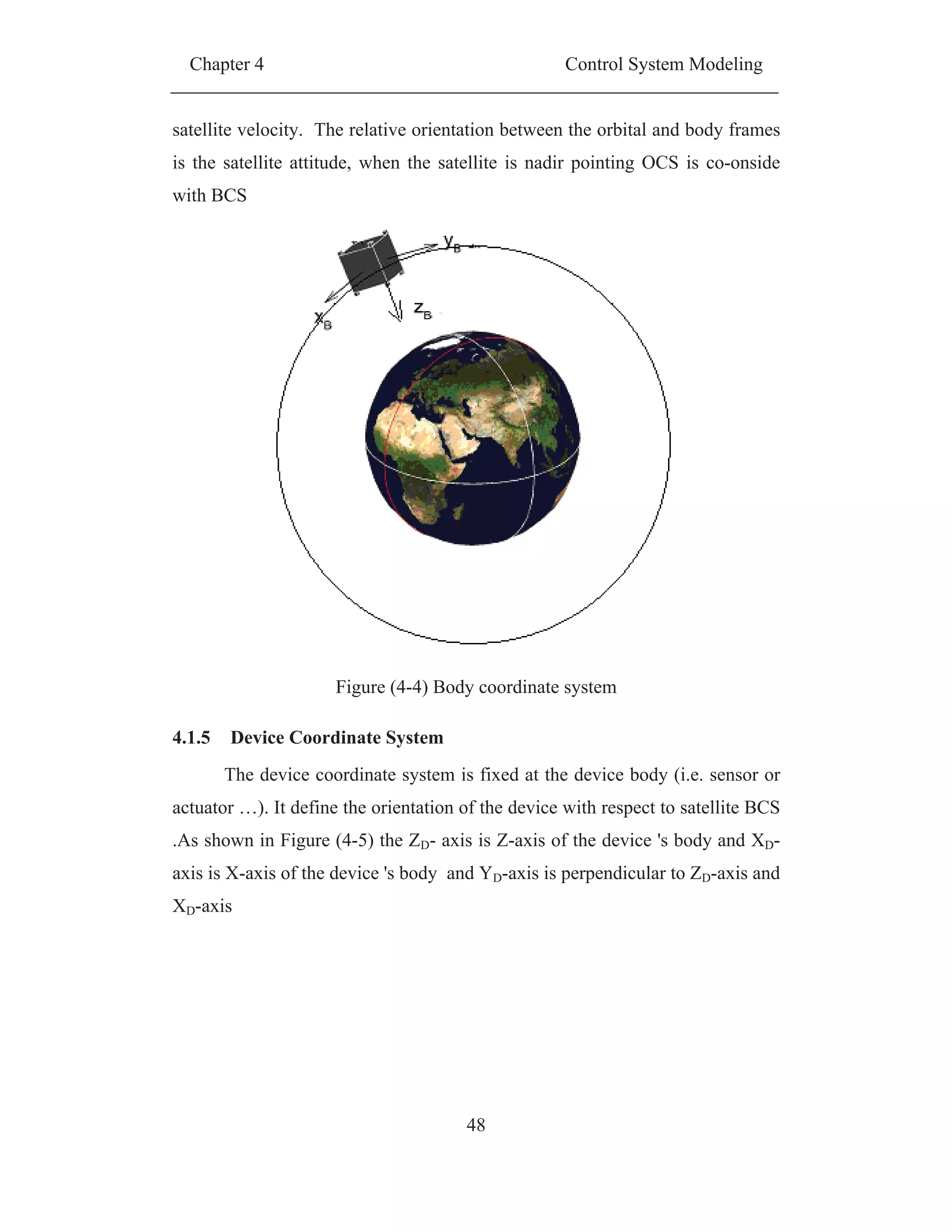
![Chapter 4 Control System Modeling
49
Figure (4-5) device coordinate system
4.2 Modeling of Satellite Rotation Around it's Center of Mass
In this section, derivation of the equations used for modeling the
kinematics and dynamics of satellite rotational motion. These equations are
borrowed of Bhanderi, 2001.
In general, kinematics equations involved in the satellite model are
represented through three types of parameters. The direction cosine matrix has
the disadvantage of having nine parameters to represent three degrees of
freedom motion. Due to this redundancy, numerous ways of representing the
satellite attitude with a minimum set of parameters have been developed.
Euler angles describe the rotation around the principal axes and use
therefore only three parameters. However some singularities arise for some
rotations, which is why Euler angles are commonly used when the attitude of
the object involved, is known to be within a certain margin to avoid this
singularities [Wertz, 1978].
Quaternions use four parameters with a single constraint, to represent
attitude, and are subjected to no singularities. This is useful when considering
that the attitude of a satellite is usually unknown after the release from the
launcher. For this reason quaternions are commonly used in space. Appendix A](https://image.slidesharecdn.com/spacecraftattitudemagneticcontroller-150428041306-conversion-gate02/75/Spacecraft-attitude-magnetic-controller-68-2048.jpg)
![Chapter 4 Control System Modeling
50
gives a brief description of the Euler angles, direct cosine matrices and
quaternions.
The modeling of a satellite’s rotational motion is divided into the
kinematic equation and the dynamic equation. The kinematic equation
describes the change in the attitude parameters of the satellite, regardless of the
forces acting on it. The dynamic equation describes the time dependent
parameters as functions of external forces.
4.2.1 Model of Dynamic Equation
Here we assume that satellite is a rigid body moving in ICS. Then
satellite motion can be described by the translation motion of its center of mass,
in addition to a rotational motion about some axis through its center of mass. In
the following analysis, depend on the well-known operator equation acting on a
given vector [13][14].
w
dt
d
dt
d
B (4.1)
Where
B vector defined in BCS
I vector defined in ICS
Figure (4-6) Angular motion of rigid body](https://image.slidesharecdn.com/spacecraftattitudemagneticcontroller-150428041306-conversion-gate02/75/Spacecraft-attitude-magnetic-controller-69-2048.jpg)
![Chapter 4 Control System Modeling
52
i
i
ii mrwrH )(
(4.6)
After performing the vector triple product, we get the following equations
i i
iiiyiiix
i
iiiz
i i
iiiziiix
i
iiiy
i i
iiiziiiy
i
iiix
mzywmzxwmxywk
mzywmyxwmzxwj
mzxwmyxwmzywiH
)(
)(
)(
22
22
22
(4.7)
Where iii zyx ,, are the coordinates of a particle i in the BCS and
zyx www ,, are the angular velocity comportments around kji ,, body axes. The
summations of the squared coordinate components are easily identified as the
three moments of inertia of the body about its three orthogonal axes. The
summations of the products of the coordinate components are identified as the
products of inertia. With these definitions equation (4.7) can be rewritten as
zyyzxxzzzyzzyxxyyyxzzxyyxxx JwJwJwkJwJwJwjJwJwJwiH
(4.8)
zyx kHjHiHH
(4.9)
If we define the angular velocity vector which describe the angular
velocity of BCS with respect to ICS as T
zyx ][ then (4.9) can be rewritten
as
I
JJJ
JJJ
JJJ
H
z
y
x
zzyzxz
yzyyxy
xzxyxx
(4.10)](https://image.slidesharecdn.com/spacecraftattitudemagneticcontroller-150428041306-conversion-gate02/75/Spacecraft-attitude-magnetic-controller-71-2048.jpg)
![Chapter 4 Control System Modeling
53
Where J the inertia tensor or inertia matrix
The dynamic equation of motion can be derived through applying
Newton’s second law for rotational motion, where the rate of change in angular
momentum of the satellite is equal to the sum of all external torques. and
recalling (4.6)
ii
k
i
i
k
i
i
vmr
HH
1
1
(4.11)
Where ir is the position of the i th
particle with mass im and velocity iv .
Taking the time derivative of Equation (4.11), yields
k
i
iiiiii amrvmvH ).( (4.12)
ia is the acceleration of the i th
particle. The first term under the
summation of Equation (4.12) is a cross product of two parallel vectors, which
is zero. Realizing that iami is the force acting on the i th
particle yields
extTH (4.13)
Where extT is the sum of external torques acting on the satellite. Such as
controlling torques cT , gravity gradient ggT and other external disturbance disT
(i.e. aero drag, magnetic disturbance….)
cdisggext TTTT (4.14)
Equation (4.13) holds only, if the internal torques sum up to zero (i.e.
the body is rigid)[10]. An expression of the derivative of the angular
momentum in terms of the satellite’s angular velocity is sought, in order to
obtain the dynamic equation.](https://image.slidesharecdn.com/spacecraftattitudemagneticcontroller-150428041306-conversion-gate02/75/Spacecraft-attitude-magnetic-controller-72-2048.jpg)

![Chapter 4 Control System Modeling
56
Gravity gradient model
According to [15] the gravity gradient torque is given as
Jerer
R
T
cm
gg 3
3
(4.28)
Where is the Earth gravitational constant, cmR is the distance from the
centre of the Earth to the satellite’s centre of gravity ( cmR is a subject of
variation, when an elliptic orbit is considered), er is the zenith. Observe that
the zenith is equivalent to is the third column in the rotation matrix from OCS
to BCS and the constant
2
3
3
O
cmR
, where O is the orbit rate.
2
3
2
2
2
1
2
0
1032
2031
2
2
er (4.29)
Where the general form of quaternion is represented in appendix A.3
By substituting the gravity gradient torque defined by equation (4.28)in
(4.27) then the full dynamic model of satellite is introduced as follows
cdisoww TTerJerHHJJ )(3 21
(4.30)
If the satellite is controlled without wheels then the dynamic model of
satellite will be
cdiso TTerJerJJ )(3 21
(4.31)](https://image.slidesharecdn.com/spacecraftattitudemagneticcontroller-150428041306-conversion-gate02/75/Spacecraft-attitude-magnetic-controller-75-2048.jpg)
![Chapter 4 Control System Modeling
59
angular velocity. Since the satellite angular velocity with respect to ICS, is sum
of the orbital angular velocity O measured in BCS and satellite relative angular
velocity[16]
yeno (4.41)
0132
2
3
2
2
2
1
2
0
0321
2
2
en (4.42)
Where en is the 2nd
column in the rotation matrix from OCS to BCS see
(A-17) .To get the kinematics differential in terms of absolute angular velocity,
substitute in (4.39) in terms of from equation (4.31) and make algebraic
arrangements
0
0
00
2
3
2
1
o
(4.43)
4.2.3 Linearized Equations of Motion
In this section, the equations of motion are linearized in terms of
quaternion to be fitted in the slandered stat space representation.
FUAXX (4.44)
Where
AIs the system matrix of linearized equations.
F Is the input matrix for control.
U Is the vector of input control torque.
The input control torque applied to this system is generated by
magnetorqure in form of interaction beteen the Earth magnetic field B and the
magentourquer dipole moment L . To obtain the input torque from the
magnetorquer, The required magnetic dipole moment is calculated as [12].](https://image.slidesharecdn.com/spacecraftattitudemagneticcontroller-150428041306-conversion-gate02/75/Spacecraft-attitude-magnetic-controller-78-2048.jpg)
![Chapter 4 Control System Modeling
61
source not found. the linearized rotation matrix from OCS to the BCS could
be easily calculated by substituting 1,0.&. 00 iiii where 3,2,1i .
122
212
221
)(
12
13
23
R (4.50)
And therefore er and en will be
1
3
1
2
2
1
2
&
1
2
2
ener (4.51)
The angular rotation rate o of the orbital frame with respect to the ICS
measured in BCS ow is
1
3
2
2
o
o
o
oo enw (4.52)
Let’s note, the vectors enand ermeet Poisson’s equations [16]
Recalling the relation (4.41).
owy (4.54)
y can be expressed as
1
3
2
0
2
o
o
y (4.55)
In addition recalling equation (4.39), therefore, satellite relative angular
velocity y can be expressed as
)(2
2
00
y
(4.56)
Assuming small angles, 3,2,1,0&0&1 00 iii .Therefore
2y (4.57)
Substituting (4.57)in (4.54)
0&0 enyneeryre (4.53)](https://image.slidesharecdn.com/spacecraftattitudemagneticcontroller-150428041306-conversion-gate02/75/Spacecraft-attitude-magnetic-controller-80-2048.jpg)
![Chapter 4 Control System Modeling
63
Where
Where
It is important to keep in mind that the values of 1 , 2 and 3 are limited
and that they are smaller than unity [12].Referring to stat space system given
in (4.44),satellite dynamics model given in (4.31) and the magnetic torque
equation (4.47) , The input matrix F is calculated as
Where 3,2,1,iBi are the components of measured Earth magnetic field.
FL
y
y
y
A
y
y
y
3
2
1
3
2
1
3
2
1
3
2
1
(4.62)
00)1(200
000060
)1(00008
2
1
00000
0
2
1
0000
00
2
1
000
3
2
3
2
2
1
2
1
oo
o
oo
A (4.63)
3
12
3
2
31
2
1
32
1 &&
J
JJ
J
JJ
J
JJ
(4.64)
2
2
2
13231
32
2
3
2
121
3121
2
3
2
2
2
1
2
1
2
1
)(
)(
BBBBBB
BBBBBB
BBBBBB
B
J
BB
B
J
F
FUUBB
B
J
Tc
(4.65)](https://image.slidesharecdn.com/spacecraftattitudemagneticcontroller-150428041306-conversion-gate02/75/Spacecraft-attitude-magnetic-controller-82-2048.jpg)
![Chapter 4 Control System Modeling
65
By taking Laplace -Transformation of (4.66) (4.68), the characteristic equation
for the motion about the x-axis and z-axis becomes
The roots of the above characteristic equation is
If 1s is a root of equation (4.72) , then for 1s to be root with non-positive
real part the following three conditions must be fulfilled[12].
since 1 , 2 and 3 are limited and that they are smaller than unity [12]
then the fowling relation are valid
From (4.75) it follows that
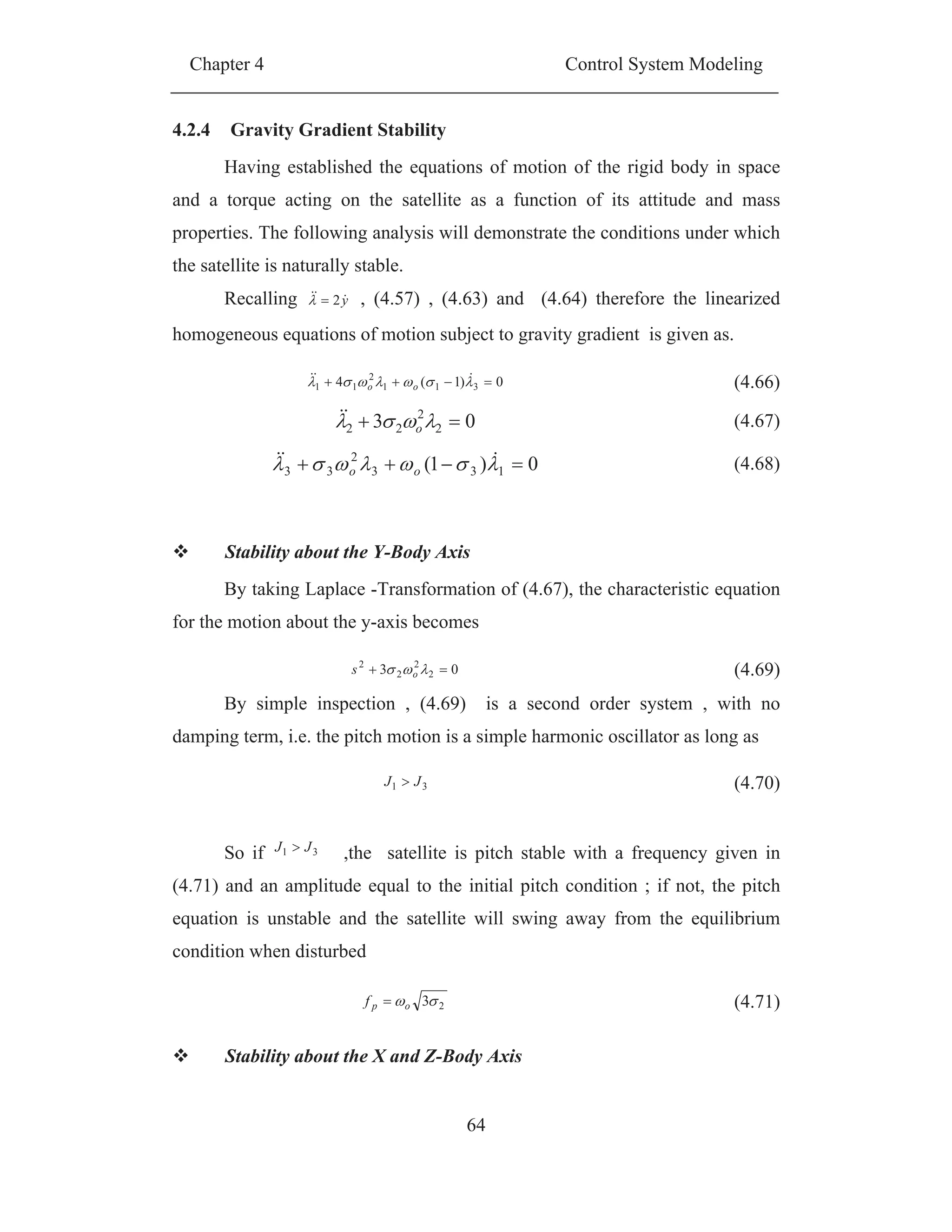
Figure (4-7)shows the regions of stability in the 31 plane resulting
from conditions (4.74) and (4.70). The four quadrants are labeled I, II, III and
IV. Quadrants II and IV are immediately instable, due to violation of condition
2nd term in (4.74) . Quadrants I and III are equally divided by a line, for which
21 ; only systems with 31 (below the dividing line) are stable. The
curve in quadrant III shows the solution to inequality in 1st term of (4.74), with
unstable systems being located below the curve. This leaves only two stable
regions, labeled A and B. for sub-region A that 312 JJJ in addition to (4.76),
for region B it follows that 321 JJJ in addition to 321 JJJ . Beletsky
derived these conditions in 1959 [17].
0431 31
2
311
24
oo ss (4.72)
2
163131 31
2
311311
2
2
o
s
(4.73)
031
0
431
311
31
31311
(4.74)
1&1&1
3
12
3
2
31
2
1
32
1
J
JJ
J
JJ
J
JJ
(4.75)
312 JJJ (4.76)](https://image.slidesharecdn.com/spacecraftattitudemagneticcontroller-150428041306-conversion-gate02/75/Spacecraft-attitude-magnetic-controller-84-2048.jpg)
![Chapter 4 Control System Modeling
66
Figure (4-7) plane showing regions of stability and instability; adapted
from[12]
4.3 Satellite center of mass motion model
Satellite motion can be considered a motion of the satellite under the
central force held of the Earth and the disturbed motion caused by other
perturbation forces. Therefore, the Keplerian orbits are important in orbit
theory and will be discussed in this section
4.3.1 Satellite orbits and Keplerian elements
The physical laws describing the motion of planets and satellites was
first described by Johann Kepler [1571-1630] and is mathematically derived
from Newton’s equations of motion for instance in Forssell (1991). Kepler’s
three laws state that:
1. The orbit of each planet is an ellipse, with the Sun at one of the foci
2. The line joining the planet to the Sun sweeps out equal areas in equal
times.
31](https://image.slidesharecdn.com/spacecraftattitudemagneticcontroller-150428041306-conversion-gate02/75/Spacecraft-attitude-magnetic-controller-85-2048.jpg)
![Chapter 5 Analysis of Conventional Controllers and
Development of a New Combined Controller
70
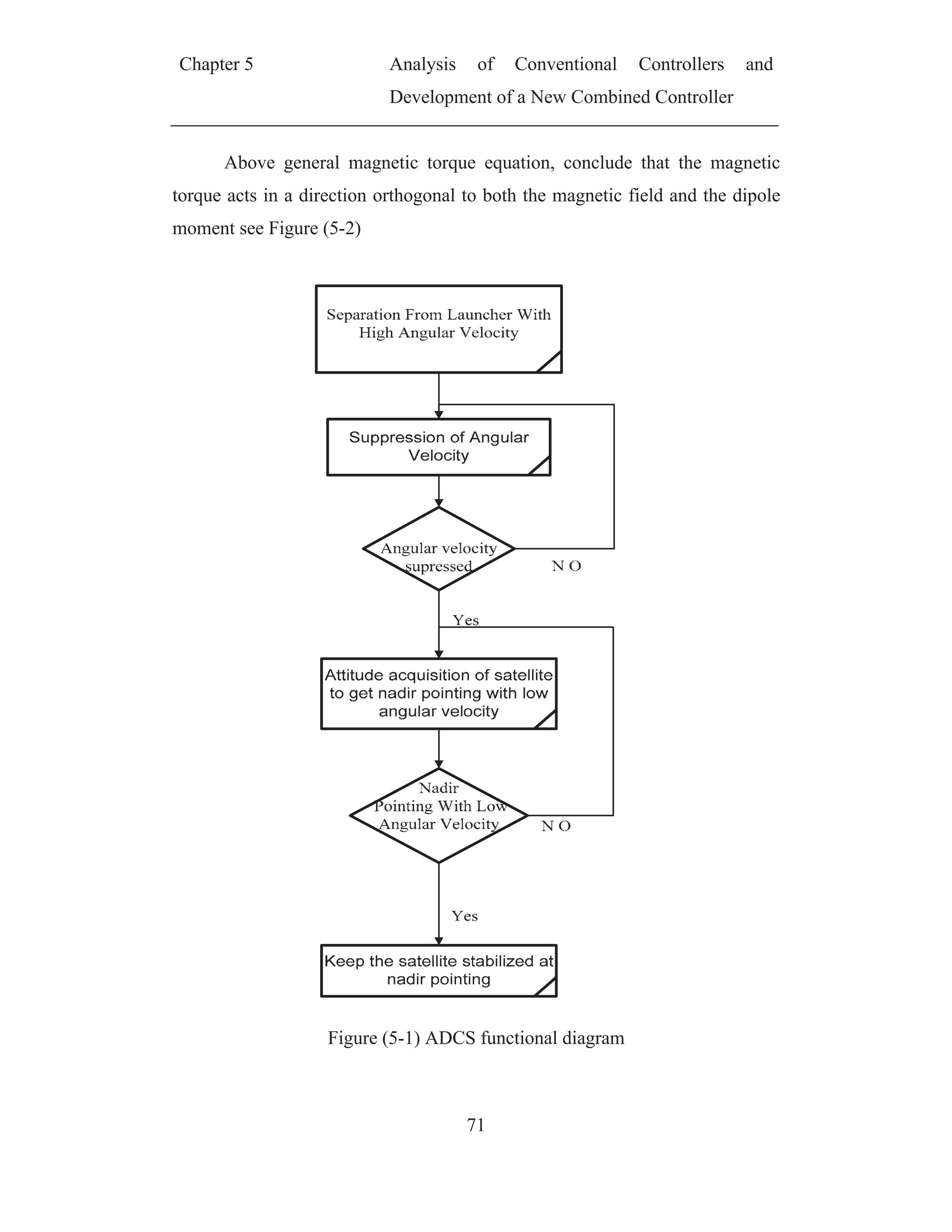
CHAPTER (5)
ANALYSIS OF CONVENTIONAL CONTROLLERS AND
DEVELOPMENT OF A NEW COMBINED
CONTROLLER
The purpose of this chapter is to present, discuss and compare between
commonly used attitude control algorithms for satellite actuated with magnetic
actuators only. Performances are demonstrated with simulations.
Since the ADCS tasks as mentioned before in 3.2 is to control the
angular motion of satellite starting from separation from launcher then attitude
acquisition and then keep satellite stabilization at nadir pointing Figure (5-1)
shows the ADCS functional diagram according to this functional diagram
ADCS magnetic control algorithms is divide to angular suppression algorithms,
in addition to attitude acquisition and stabilization algorithms[18],[19] in all
previous works attitude acquisition and stabilization are considered similar and
the same control law is used in both [20],[21].
5.1 Attitude Magnetic control concept
The main concept of magnetic attitude control of satellite is to generate
dipole moment L . Which is reacting with the earth magnetic filed B generating
torque cT used to orient the satellite.
BLTC (5.1)](https://image.slidesharecdn.com/spacecraftattitudemagneticcontroller-150428041306-conversion-gate02/75/Spacecraft-attitude-magnetic-controller-89-2048.jpg)
![Chapter 5 Analysis of Conventional Controllers and
Development of a New Combined Controller
72
Figure (5-2) Magnetic Torque Direction
often, the desired direction of torque is not perpendicular to the magnetic
field. In this case, only the component of the desired torque in the direction
perpendicular to the magnetic field is possible and can be developed. This
relationship is demonstrated graphically in where dT is the desired torque , or
ideal, torque, , genT is an generated magnetic torque and is the undesired
component of torque, as described in [22]see Figure (5-3)
The moment developed in MT is determined by attempting to minimize
the magnitude of the undesired magnetic torque, T , such that
gend TT minimum (5.2)
This leads to [12]
2
B
TB
L d
(5.3)](https://image.slidesharecdn.com/spacecraftattitudemagneticcontroller-150428041306-conversion-gate02/75/Spacecraft-attitude-magnetic-controller-91-2048.jpg)
![Chapter 5 Analysis of Conventional Controllers and
Development of a New Combined Controller
73
Figure (5-3) Magnetic Control Torques[23]
5.2 Controllability
The satellite actuated by a set of magnetorquers has a serious
limitation[26]. The mechanical torque, produced by the interaction of the
geomagnetic field and the magnetic field generated by the magnetorquers, is
always perpendicular to the geomagnetic field vector. Thus, the direction
parallel to the geomagnetic field vector is not controllable. The geomagnetic
field changes its orientation in the OCS when the satellite moves in orbit. This
implies that e.g. yaw is not controllable over the poles but controllable over the
equator, see Figure (5-4)
Therefore beside the magnetic control it is required another source of
torque to control the satellite, when it is magnetically uncontrollable. This
source of torque can be expensively achieved by so-called momentum bias
configuration [12],[15] or cheaply achieved by using gravity gradient](https://image.slidesharecdn.com/spacecraftattitudemagneticcontroller-150428041306-conversion-gate02/75/Spacecraft-attitude-magnetic-controller-92-2048.jpg)
![Chapter 5 Analysis of Conventional Controllers and
Development of a New Combined Controller
74
torque[18]. Our study will focus in using gravity gradient torque beside the
magnetic torque to control the satellite
Figure (5-4)Control torque is always perpendicular to the geomagnetic field
vector.
This implies that yaw is not controllable over poles, and roll is not controllable
over equator.
5.3 Angular Velocity Suppression
The objective of the angular velocity suppression or detumbling
controller is to suppress the high angular velocity of satellite obtained due to
separation from launcher. Commonly there are two methods used for satellite
angular suppression, angular velocity feed back and B-dot technique](https://image.slidesharecdn.com/spacecraftattitudemagneticcontroller-150428041306-conversion-gate02/75/Spacecraft-attitude-magnetic-controller-93-2048.jpg)
![Chapter 5 Analysis of Conventional Controllers and
Development of a New Combined Controller
75
5.3.1 Angular suppression using velocity feed back
The main idea here is to use controller able to dissipate the satellite high
energy gained during separation from launcher. A very simple controller is
suggested in [20] which use angular velocity measurements from gyro, the
functional block diagram for velocity feedback controller is shown in Figure
(5-5 ). The stability of velocity feedback is examined below using the energy
consideration
Figure (5-5) Function diagram of velocity suppression using velocity feed
back algorithm
5.3.1.1 Energy Considerations
The total energy of the satellite is divided into kinetic and potential
energy. Kinetic energy is principally a result of the rotation in the inertial and
Required
Dipole
Moment
ADCS Processor
MTz
MTy
MTx MM
Gyro
Control
Algorithms
B
B
Satellite](https://image.slidesharecdn.com/spacecraftattitudemagneticcontroller-150428041306-conversion-gate02/75/Spacecraft-attitude-magnetic-controller-94-2048.jpg)
![Chapter 5 Analysis of Conventional Controllers and
Development of a New Combined Controller
76
orbit frame. The sources for the potential energy are the gravity gradient and
gyro effects due to revolution about the Earth [18].
Kinetic Energy
The standard kinetic energy of the satellite is a quadratic form relating
the satellite absolute angular velocity with respect to ICS. In this study we
focus only on the rotation of the satellite w.r.t the reference coordinate system,
i.e. the OCS.
The total angular velocity of the satellite relative to ICS is a sum of the
satellite angular velocity w.r.t. the OCS, y and the angular velocity of the
satellite’s revolution about the Earth (i.e. the orbital rate), o . It is assumed that
the orbit is circular and thus the orbital rate, is constant, therefore the portion
due to the orbital rate is disregarded, then kinetic energy of the angular motion
is expressed as
yJyE T
Kin
2
1
(5.4)
Potential energy
The potential energy due to the gravity gradient is minimum (Egg = 0)
when the z- axis of BCS (the axis of minimum moment of inertia) is ideally
aligned with the z-axis of OCS, since there is no gravity gradient acting on the
satellite. Its maximum value is reached when the satellite attitude is such that
the z-axis of BCS coincides with the y-axis of OCS. The potential energy
associated with the gravity gradient can be then considered as a measure of the
inclination angle between z-axes of OCS and BCS. It is formulated as,
)(
2
3 2
zz
T
ogg JerJerE (5.5)](https://image.slidesharecdn.com/spacecraftattitudemagneticcontroller-150428041306-conversion-gate02/75/Spacecraft-attitude-magnetic-controller-95-2048.jpg)
![Chapter 5 Analysis of Conventional Controllers and
Development of a New Combined Controller
77
Where the vector er - as it was defined in (4.29) - is a unit vector
describes the orientation between z-axes of OCS and BCS .The moment of
inertia about the z- xis, zzJ , is subtracted from the right hand side of Eq.
(5.5)[20] to make the minimum energy equal to zero.
The potential energy has also a component originating from the
revolution of the satellite about the Earth. Consider the summand J in the
equation of dynamics(4.31) . Using (4.41) this term can be rewritten as
enJenenJyyJenyJyJ ooo
2
(5.6)
Where the vector en - as it was defined in (4.42) is a unit vector
describes the orientation between y-axes of OCS and BCS. Since enJeno
2
is
not dependent on the satellite's angular velocity, and hence gives a contribution
only to the potential energy. therefore, the potential energy due to the
revolution of the satellite about the Earth is
)(
2
1 2
enJenJE T
yyogyro (5.7)
The minimum of this energy (Egyro = 0) is obtained when the y axis of
BCS is aligned with the y axis of OCS, and maximum when the z axis of BCS
coincides with the y axis of OCS. The moment of inertia about the y- axis, yyJ ,
is added to the right hand side of (5.7) to make the minimum energy equal to
zero.The total energy can be expressed as
gyroggkintot EEEE (5.8)
Therefore, the complete form of the total energy is,
)(
2
1
)(
2
3
2
1 22
enJenJJerJeryJyE T
yyozz
T
o
T
tot (5.9)
5.3.1.2 Lyapunov Stability
Consider a Lyapunov candidate function expressing the total energy of
the satellite.](https://image.slidesharecdn.com/spacecraftattitudemagneticcontroller-150428041306-conversion-gate02/75/Spacecraft-attitude-magnetic-controller-96-2048.jpg)
![Chapter 5 Analysis of Conventional Controllers and
Development of a New Combined Controller
79
neJenreJer
yJenySneJTJererSyE
T
o
T
o
oooco
T
tot
22
2
3
()()(3(
(5.19
)
Using that 0)()( ySyT
and (5.15) we get
yenSJenyerSJer
enyJenyS
yenJSTJererSyE
T
o
T
o
oo
oco
T
tot
).().(3
))()(
).(.)(3(
22
2
(5.20)
This reduced to the simple expression
c
T
tot TyE (5.21)
Finally, we have
c
T
tot TyEV (5.22)
So if the controlling torque is chosen as angular velocity feedback as
shown below in (5.23)
yKT vC . (5.23)
Where
vK is the positive constant
Then,
yKyV v
T
.. (5.24)
Therefore, the satellite energy will dissipate, and the controller (5.23)
guarantees damming of the relative angular velocity to zero. Hence the
required dipole moment to generate the control torque (5.23) can be calculated
using (5.25)[12]
2
B
TB
L c
(5.25)
Where
L is the dipole moment
B is the earth magnetic filled](https://image.slidesharecdn.com/spacecraftattitudemagneticcontroller-150428041306-conversion-gate02/75/Spacecraft-attitude-magnetic-controller-98-2048.jpg)
![Chapter 5 Analysis of Conventional Controllers and
Development of a New Combined Controller
81
Since derivative of earth magnetic filed in BCS as given [28]
ByB (5.32)
Finally becomes the B-dot detumbling control law
BKL (5.33)
Therefore, the dipole moment calculated by the form (5.31) guarantees
satellite dissipation.
5.3.2.1 Angular suppression using B-dot technique No.1
Since the derivative of earth magnetic field B can be calculated using
magnetometer measurements and satellite relative angular velocity using
(5.32). However, the relative angular velocity y is calculated using (4.41) from
gyro measurements and orbital rat o by the following form
eny o (5.34)
Since the orbital rate is very small compared with satellite angular
velocity during detumbling mode and it can be neglected so equation (5.31)
can be rewritten as
)( BKL (5.35)
The block diagram for Angular suppression using B-dot technique No.1
is shown in Figure (5-6.)](https://image.slidesharecdn.com/spacecraftattitudemagneticcontroller-150428041306-conversion-gate02/75/Spacecraft-attitude-magnetic-controller-100-2048.jpg)
![Chapter 5 Analysis of Conventional Controllers and
Development of a New Combined Controller
82
BB
BKL
Figure (5-6 ) Block diagram of velocity suppression using B-dot technique No1
5.3.2.2 Angular suppression using B-dot technique No2
Here a simple way used to calculate the derivative of earth magnetic
field B done by a simple backwards difference method (i.e. calculation of the
difference between two successive magnetometer measurement
)(),( dTtBtB divided by the difference between the times measurements dT
) [23].
dT
tBdTtB
B
)()(
(5.36)
Then the required dipole moment is calculated from (5.33), The block
diagram for Angular suppression using B-dot technique No.2 is shown in
Figure (5-7)](https://image.slidesharecdn.com/spacecraftattitudemagneticcontroller-150428041306-conversion-gate02/75/Spacecraft-attitude-magnetic-controller-101-2048.jpg)
![Chapter 5 Analysis of Conventional Controllers and
Development of a New Combined Controller
83
dT
kBkB
B
)1()(
BKL
Figure (5-7 )Block diagram of velocity suppression using B-dot technique No2
5.3.2.3 Angular suppression using B-dot technique No3
This technique was developed by M Guelman and used in the Israeli
Guerwin-Techsat This satellite was a 50kg cube, launched in July 1998, and
successfully functioned for over 4.5 years. [23] the derivative of the magnetic
filed is calculated as
dT
tBdTtB
B
tBtBtB o
)()(
)()()(
(5.37)](https://image.slidesharecdn.com/spacecraftattitudemagneticcontroller-150428041306-conversion-gate02/75/Spacecraft-attitude-magnetic-controller-102-2048.jpg)
![Chapter 5 Analysis of Conventional Controllers and
Development of a New Combined Controller
85
5.3.3 Simulation verification
The following data are used for verification of the above mentioned
angular velocity suppression controllers
Table 5-1initial data used for satellite simulation
Parameter Value
Satellite moment of inertia tensor
[kgm2
]
406.008.0
06.0805.0
08.005.06
Initial satellite angular velocity
[deg/s]
T
5.45.45.4
Maximum dipole moment
generated from MT [Am2
]
10
orbit altitude [Km] 660
Orbit eccentricity 0
Orbit inclination [deg.] 98
Orbit argument of perige [deg.] 0
Local time of ascending node 10:00 am
True anomaly[deg.] 0
Satellite residual dipole moment
Am2
T
2.03.05.0
Calculation of the desired final angular velocity
As it is shown in (5.24) the angular velocity feedback guarantees the
convergence of satellite angular velocity to zero. In other hand, because the
results of angular velocity feedback algorithm will be compared with those
using B-dot technique. Taking into consideration that the minimum angular
velocity using B-dot technique is achieved when the satellite follows the
magnetic filed (i.e. behave like a compass). Since, the magnetic filed rotates
two times pre orbital period (i.e. 6000 s for 660 km orbit altitude), therefore the
min angular velocity reached by B-dot technique is calculated as flows
sy o
o
d /12.0
3000
360
(5.38)](https://image.slidesharecdn.com/spacecraftattitudemagneticcontroller-150428041306-conversion-gate02/75/Spacecraft-attitude-magnetic-controller-104-2048.jpg)
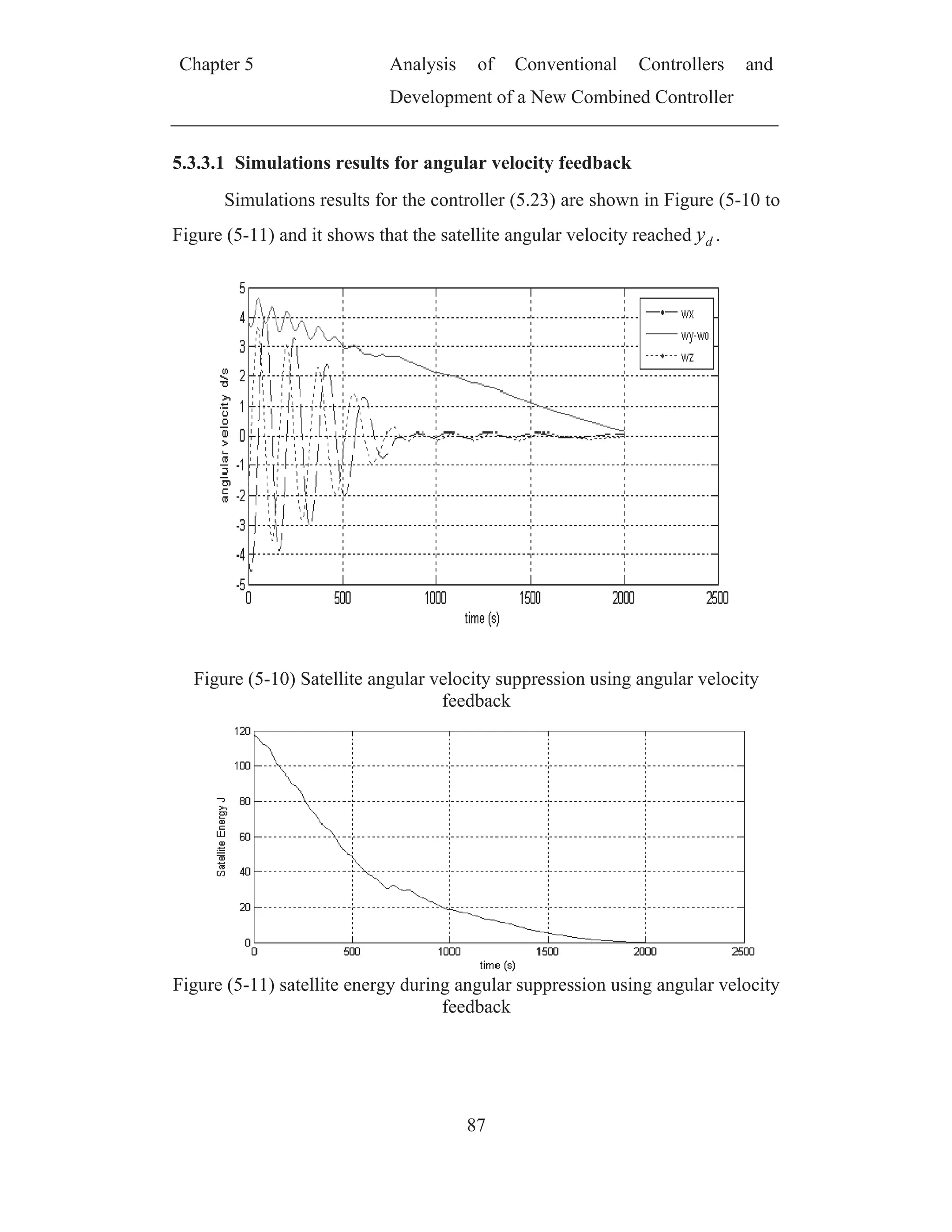
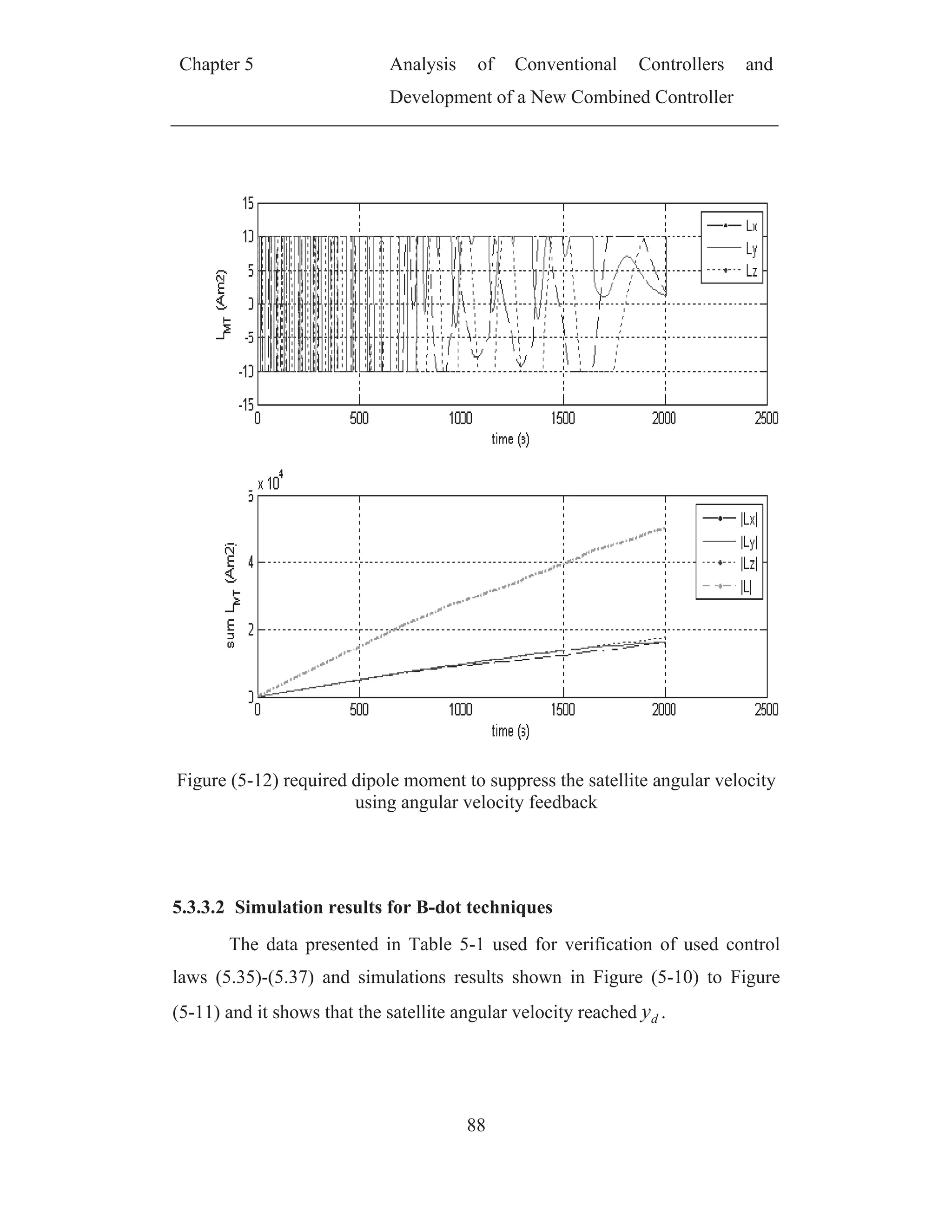
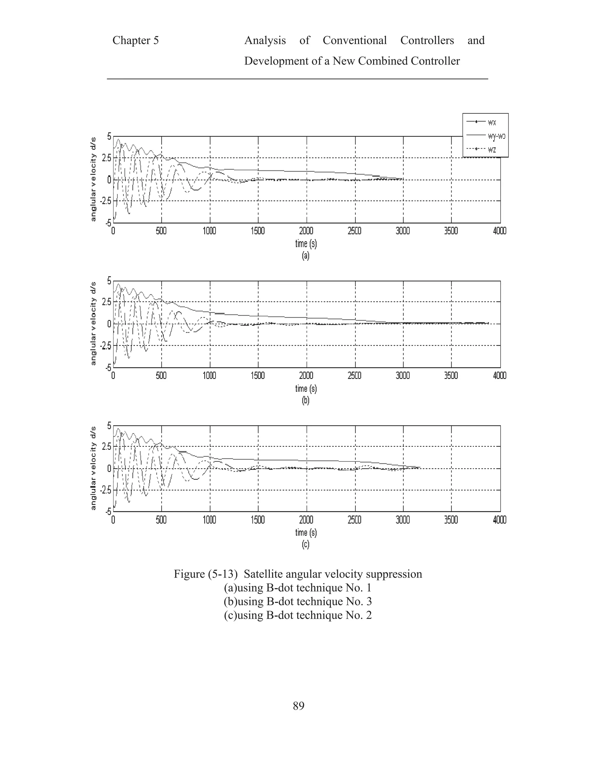
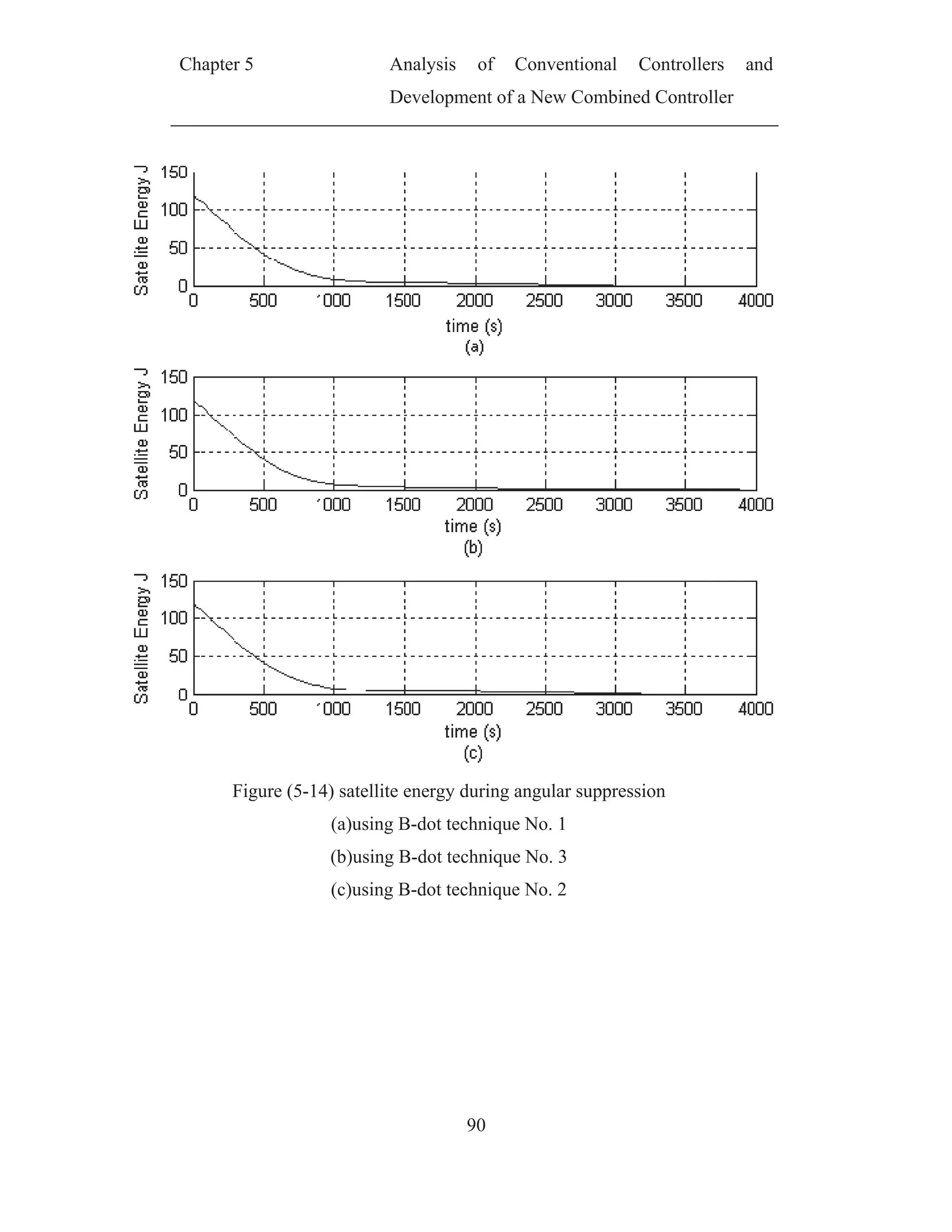
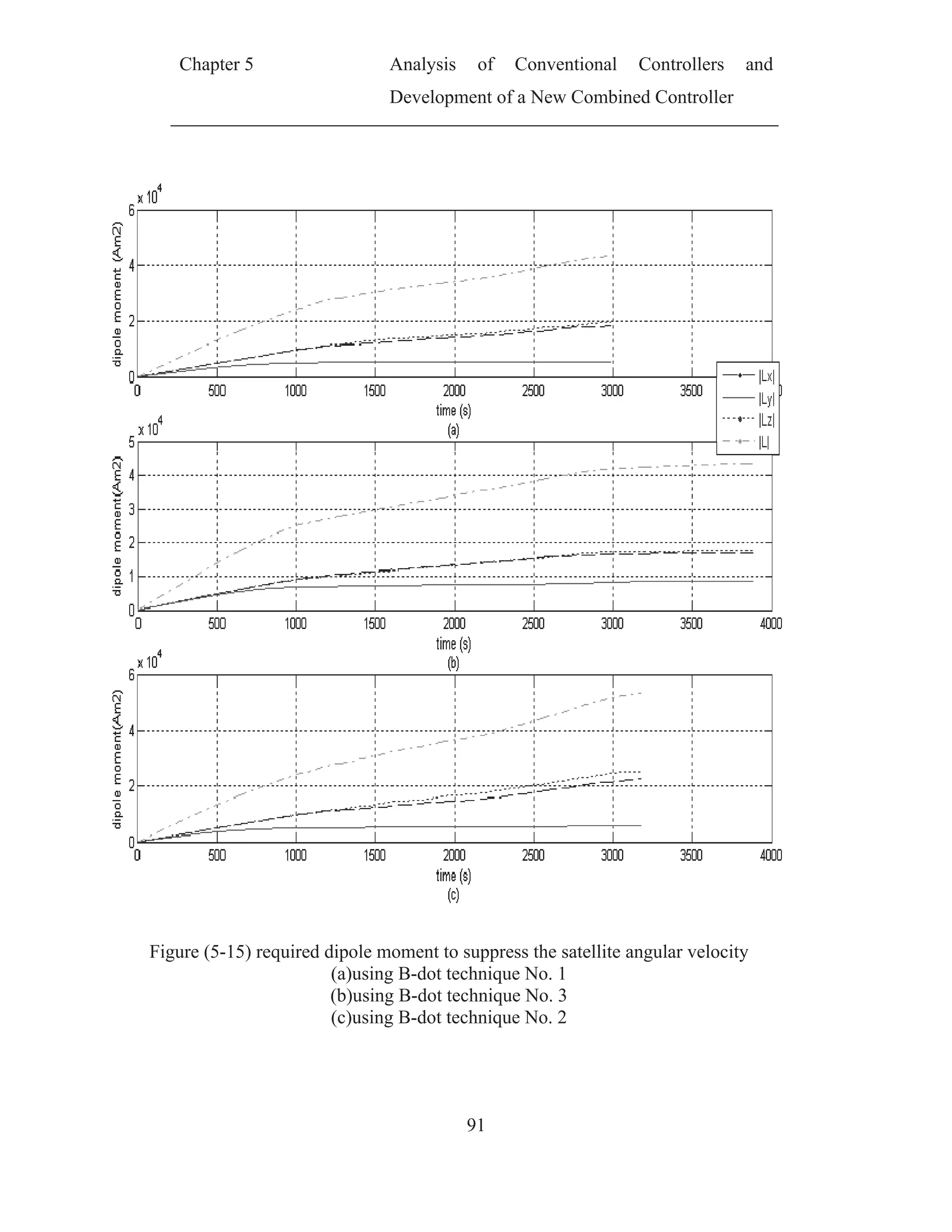
![Chapter 5 Analysis of Conventional Controllers and
Development of a New Combined Controller
92
5.3.4 Comparison between angular velocity suppression algorithms
A comparison between performance , execution characteristics and cost
for the above mentioned angular velocity suppression algorithms. In order to
show the advantages and disadvantages for each one.
The comparison parameters used for evaluation are:
1. The required time to finish the angular velocity suppression (i.e.
sy o
/13.0 ), supT .
2. Required dipole moment until finishing angular velocity suppression,
supL .
3. The calculation time for one cycle of the algorithm calT
4. Qualitative the estimation cost .
For the calculation time for one cycle of the algorithm the following
environments was used for the evaluation.
Algorithm was developed and run using Borlandc 3.11.
Run on PC with Pentium (D) CPU 3.40 GHz. With 1 GB RAM
Used operating system XP SP2
The following table summaries the comparison results
Table 5-2the comparison result between angular velocity suppression
algorithms
Angular
velocity
feedback
B-dot
Technique
No1
Technique
No2
Technique
No3
acqT [s] 2004 2988 3885 3181
acqL [Am2
] 5.002e4 4.363e4 4.336e4 5.344e4
calT [s] 4.396e-6 3.605e-6 3.287e-6 1.4305e-4
cost Need MM and
Gyros
Need MM
and Gyros
Need MM
only
Need MM
only](https://image.slidesharecdn.com/spacecraftattitudemagneticcontroller-150428041306-conversion-gate02/75/Spacecraft-attitude-magnetic-controller-111-2048.jpg)
![Chapter 5 Analysis of Conventional Controllers and
Development of a New Combined Controller
94
In the next subsections, adscription for the above mentioned controllers
and simulation results will be presented then comparison between them will be
introduced.
5.4.1 PD-Like Controller
Three axes attitude control requires accurate attitude knowledge to
function correctly. So PD-like controller [12] will be used, here the feedback
from relative angular velocity is used instead of the derivative of
quaternion[24]. Therefore, the algorithm itself becomes just a simple rate and
position feedback; hence the required magnetic torque can be calculated as
follows
pvc kykT (5.39)
Where
vk Positive rate gain constant
pk Positive position gain constant
And the required dipole moment will be
2
B
TB
L c
(5.40)
For this controller, the attitude and angular velocity are fed back into the
system
Function diagram of PD-like controller is shown below](https://image.slidesharecdn.com/spacecraftattitudemagneticcontroller-150428041306-conversion-gate02/75/Spacecraft-attitude-magnetic-controller-113-2048.jpg)
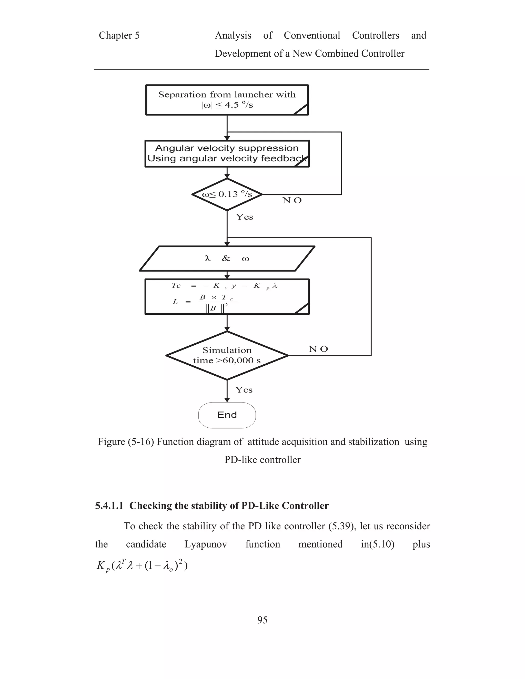
![Chapter 5 Analysis of Conventional Controllers and
Development of a New Combined Controller
97
signals. The objective of the attitude control is to get nadir pointing; the design
strategy of the sliding mode controller consists of two steps,
1. Sliding manifold design.
2. Sliding condition design.
The description and design of skidding mode controller are based on
[20]
5.4.2.1 Sliding Manifold Design
Consider manifold, a 3 dimensional hyper plane, in the state space of a
6th order system
T
y .The sliding manifold is designed in such a way that the
satellite trajectory, if on the hyper plane, converges to the reference. However,
the satellite motion is not confined to the 3 dimensional hyper plane in general.
Therefore, a control law forcing the satellite motion toward the manifold is
necessary for achieving stable satellite motion
Let a sliding variable s be defined as in
qAyJs (5.46)
Where qA
is a positive definite matrix.
The sliding manifold is the subspace of the state space, where the sliding
variable equals
}0:,{ syS (5.47)
The definition of the sliding variable,s , guarantees convergence of to
zero with an exponential rate. To prove this statement, consider a Lyapunov
candidate function
)1(2
)1( 2
o
o
T
V
(5.48)
The time derivative of the Lyapunov candidate function is calculated
applying the kinematics
yV T
(5.49)](https://image.slidesharecdn.com/spacecraftattitudemagneticcontroller-150428041306-conversion-gate02/75/Spacecraft-attitude-magnetic-controller-116-2048.jpg)
![Chapter 5 Analysis of Conventional Controllers and
Development of a New Combined Controller
99
The derivatives of the satellite angular velocity and the attitude
quaternion are calculated according to the equations of kinematics and
dynamics,(4.31),(4.43).
coqo TyyAyenJJererJs )(
2
1
)(3 2
(5.52)
Assume that the satellite trajectory is on the sliding manifold. An
equivalent torque eqT is a control torque necessary to keep the satellite on the
sliding manifold. In other words, if the control torque cT is equal to the
equivalent torque eqT then the time derivative of the sliding variable equals zero.
If the satellite is not on the sliding manifold, a desired control torque dT equals
the sum of the equivalent torque eqT and a part making the sliding variable
converge zero [20]
)(ssignATT seqd (5.53)
Where
sA is a positive definite matrix and
)(
2
1
)(3 2
yyAyenJJererJT oqoeq (5.54)
And according to[20]
2
B
TB
L d
(5.55)
The Block diagram of attitude acquisition and stabilization using sliding
mode is shown below](https://image.slidesharecdn.com/spacecraftattitudemagneticcontroller-150428041306-conversion-gate02/75/Spacecraft-attitude-magnetic-controller-118-2048.jpg)
![Chapter 5 Analysis of Conventional Controllers and
Development of a New Combined Controller
100
qAyJs
Figure (5-17) Block diagram of attitude acquisition and stabilization using
sliding mode
5.4.3 Linear Quadratic Regulator
The satellite dynamics are quite nonlinear, but about the reference a
linear approach to control design is attractive. Traditionally LQR (Linear
Quadratic Regulator) has been used on magnetic actuated satellites because of
their reliability and robustness. The LQR strategy is based on linearizing the
systems dynamics, defining an object function which shall be minimized and
generate a gain matrix which is used for feedback. For more details on LQ-
control problems see [20],[27].](https://image.slidesharecdn.com/spacecraftattitudemagneticcontroller-150428041306-conversion-gate02/75/Spacecraft-attitude-magnetic-controller-119-2048.jpg)
![Chapter 5 Analysis of Conventional Controllers and
Development of a New Combined Controller
101
The linearization of the satellites attitude was derived in section 4.2.3
recalling the system of differential equation that describe the linear mode of the
satellite (4.61)
)().()(.)( tLtFtxAtx
(5.56)
Where matrices Aand )(tF are defined in (4.63) and (4.65)
The cost function which should be to minimized is[25]:
dtuPuxQxJ
T
to
op ]....[
(5.57)
The matrices Q and P are positive semidefinite and are used to weight
state and actuator usage. The solution to the LQ-problem is given by the Ricatti
equation
QtRtFPtFtR
tRAAtRtR
ric
T
ric
ric
T
ricric
)()()()(
)()()(
1
(5.58)
The solution of the LQR problem yields the time varying controller
)()()()( 1
txtRtFPtL ric
T
(5.59)
The block diagram of LQR is shown below](https://image.slidesharecdn.com/spacecraftattitudemagneticcontroller-150428041306-conversion-gate02/75/Spacecraft-attitude-magnetic-controller-120-2048.jpg)
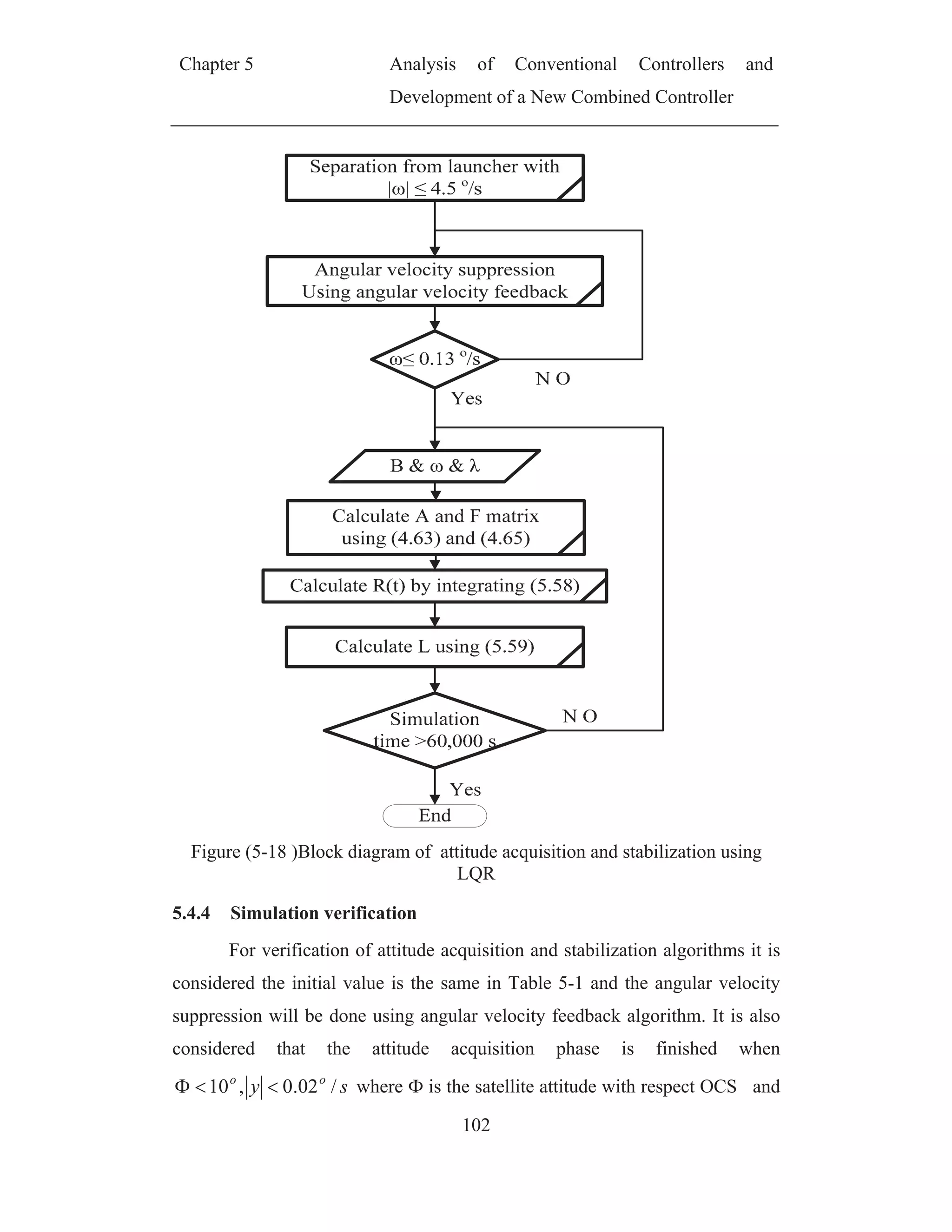
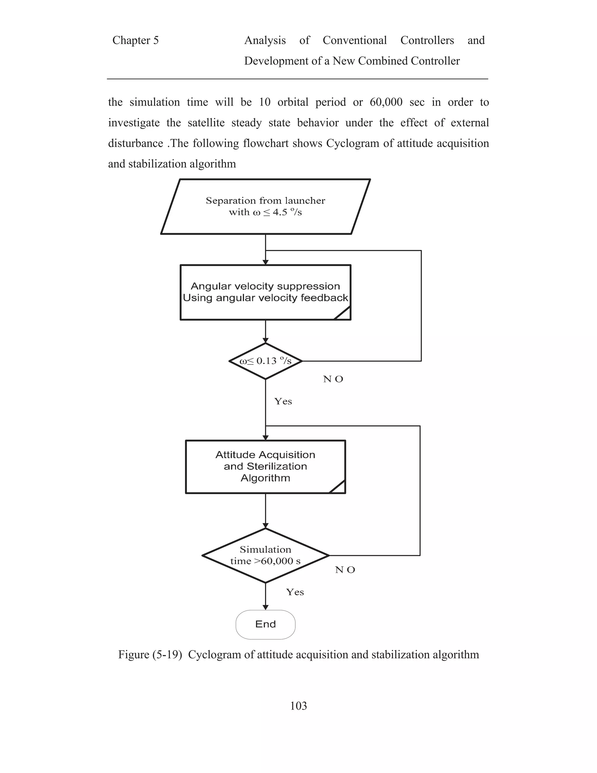
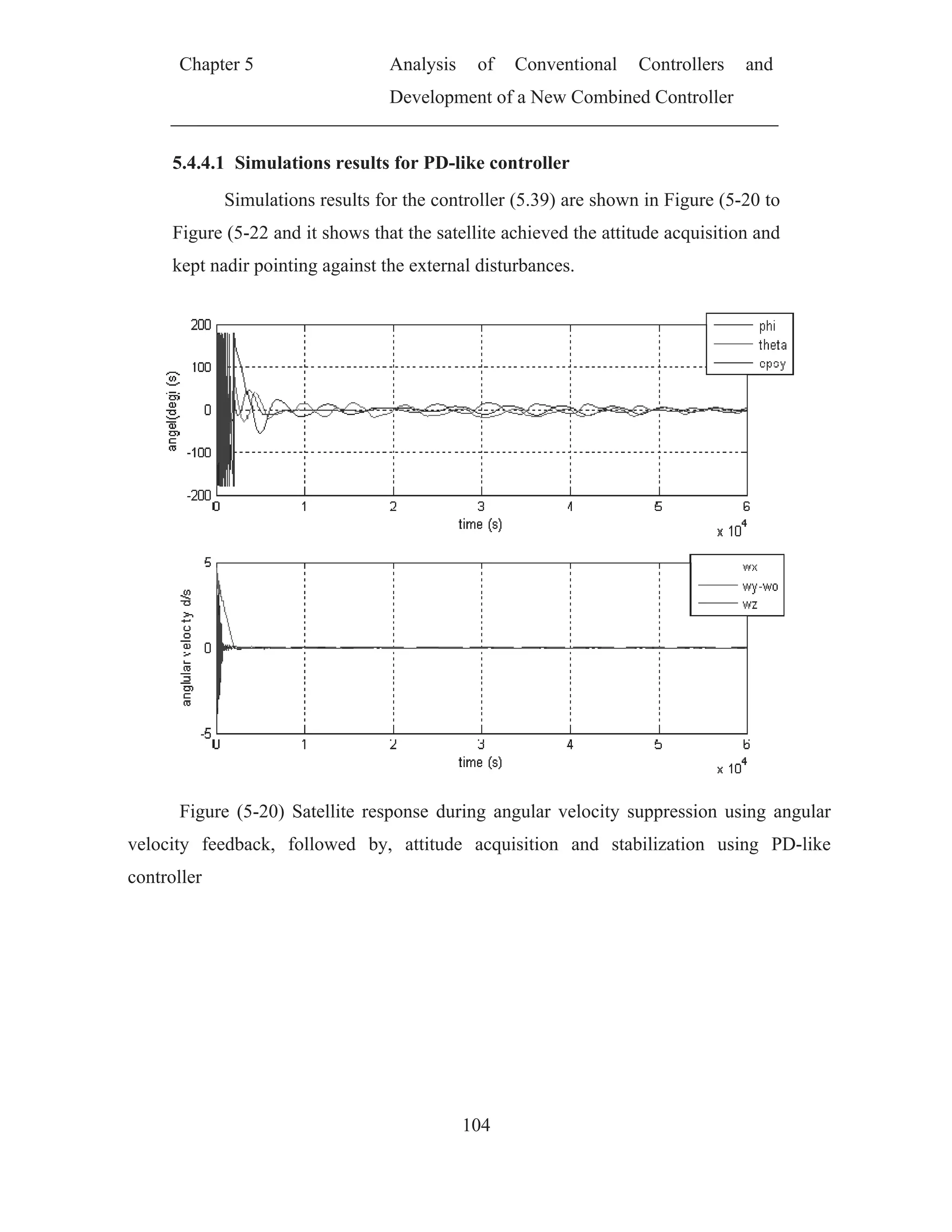
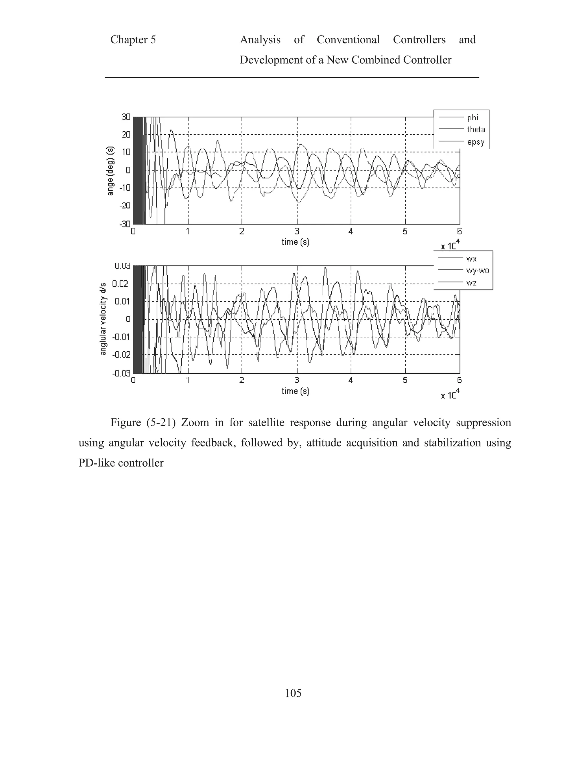
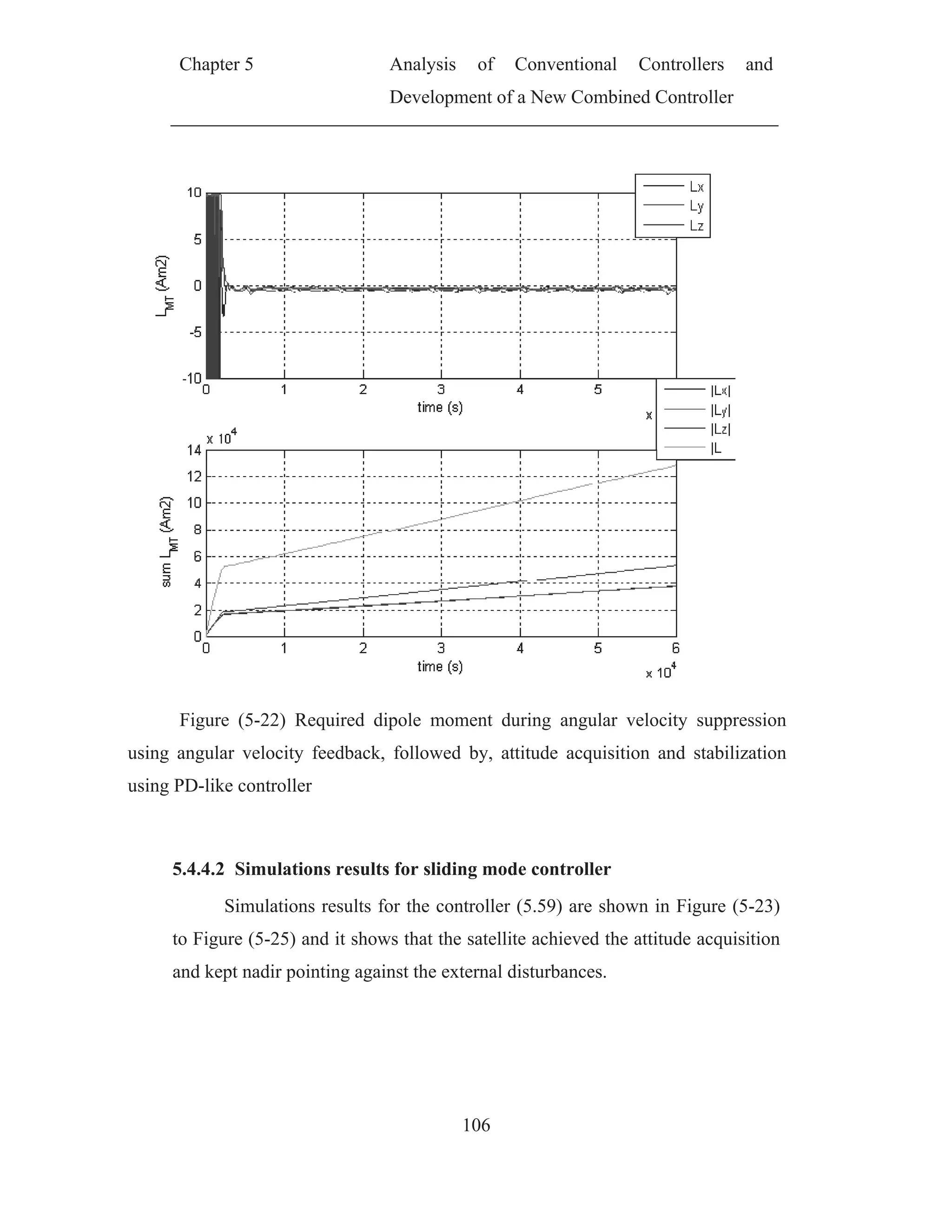
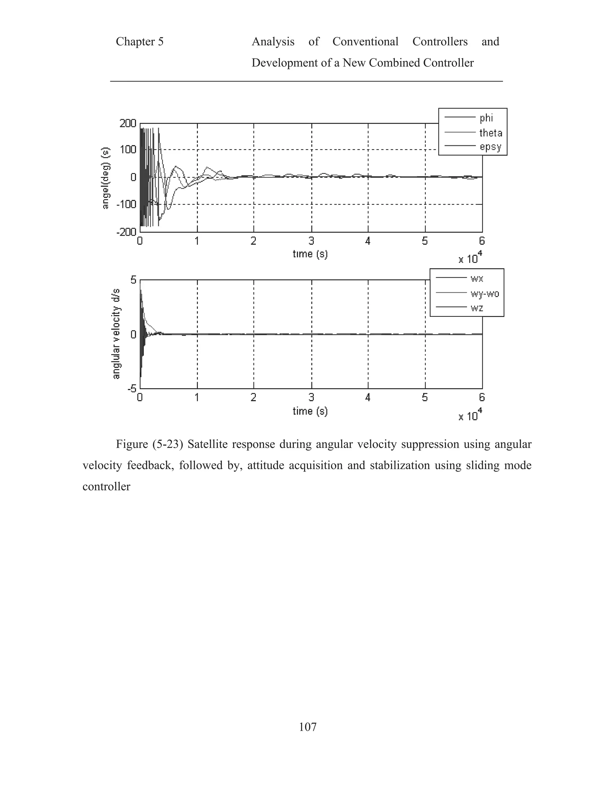
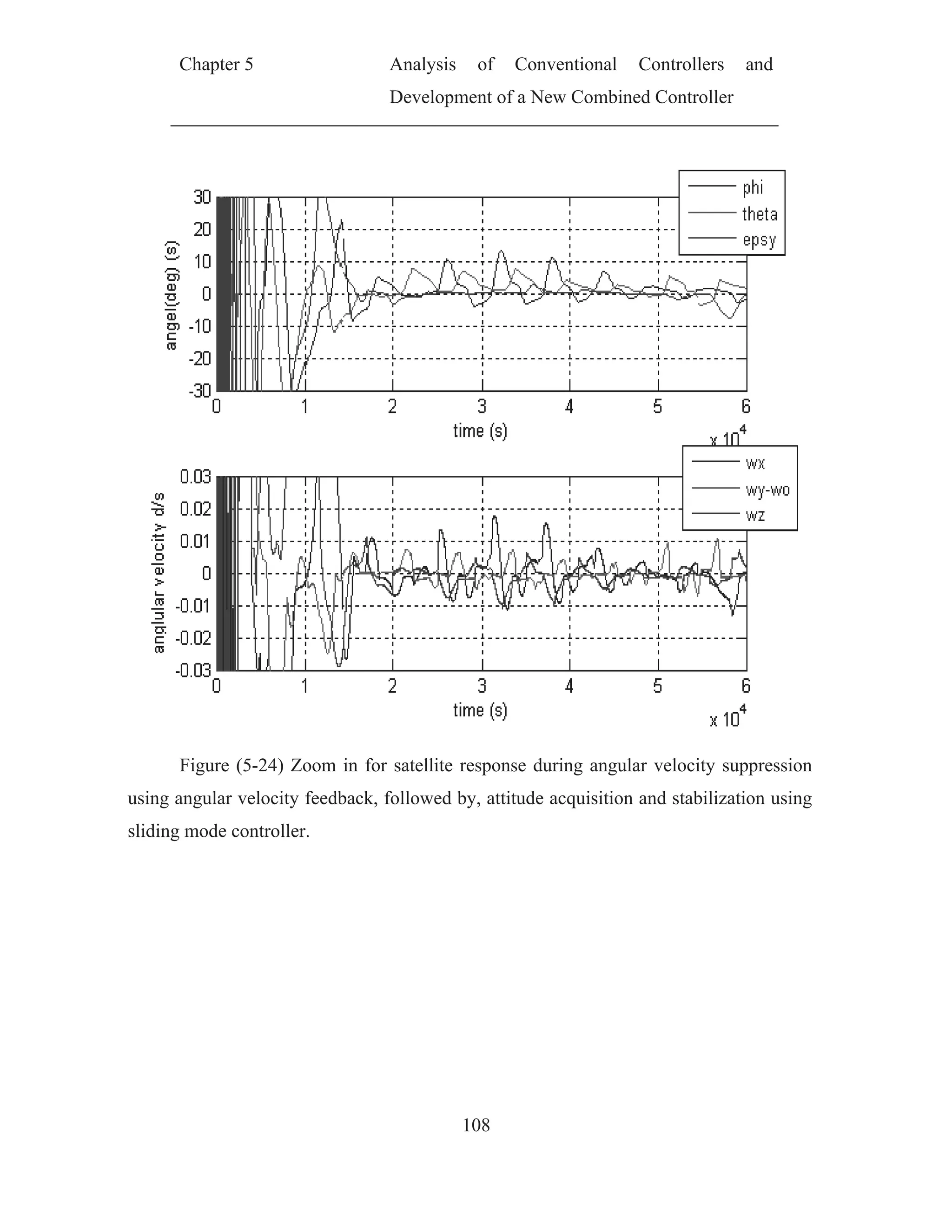
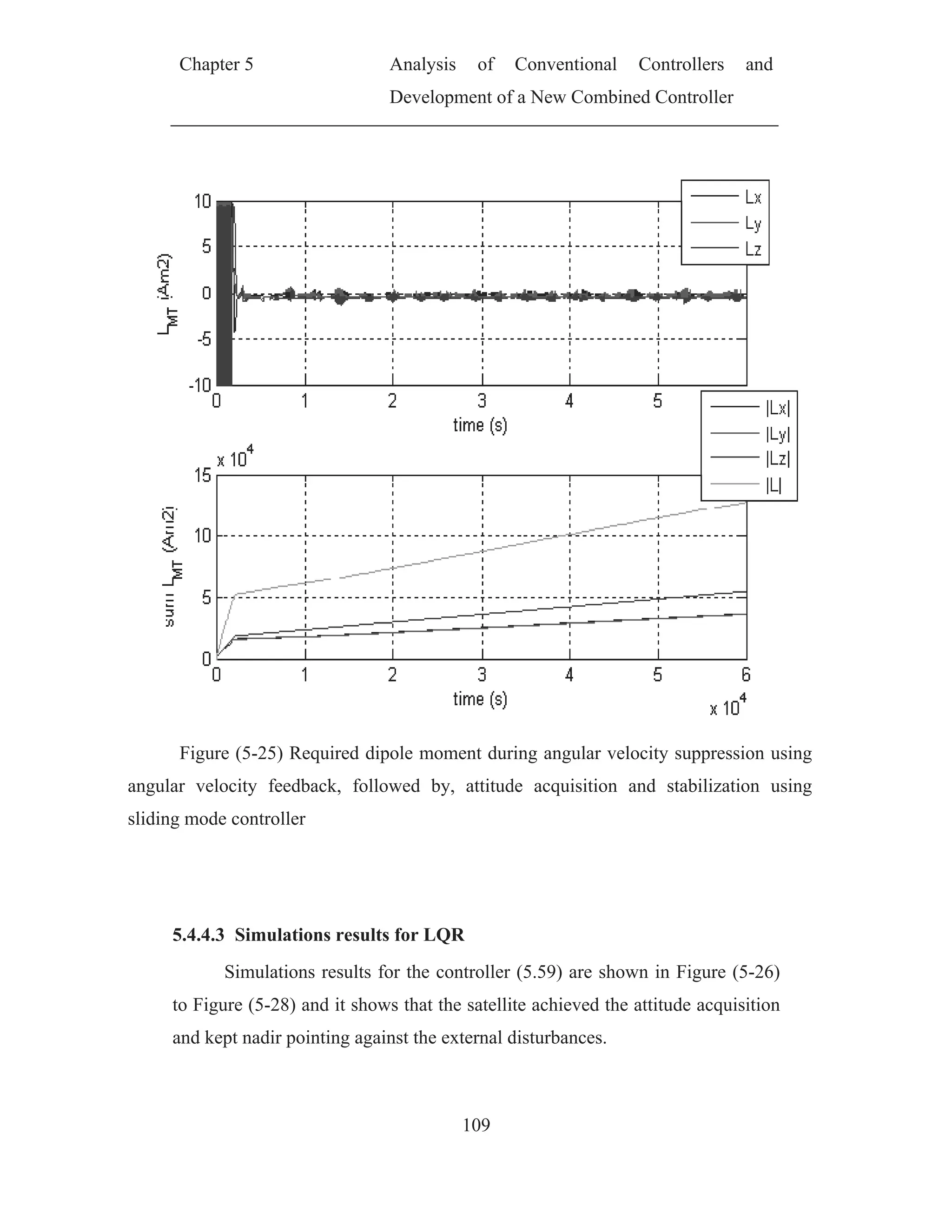
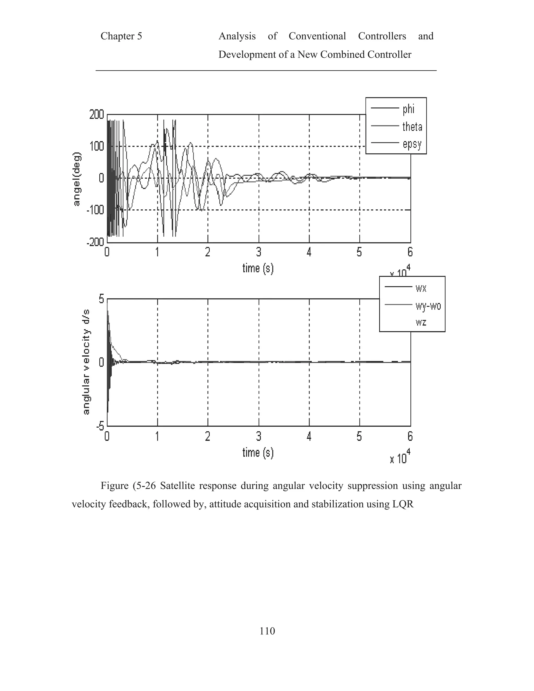
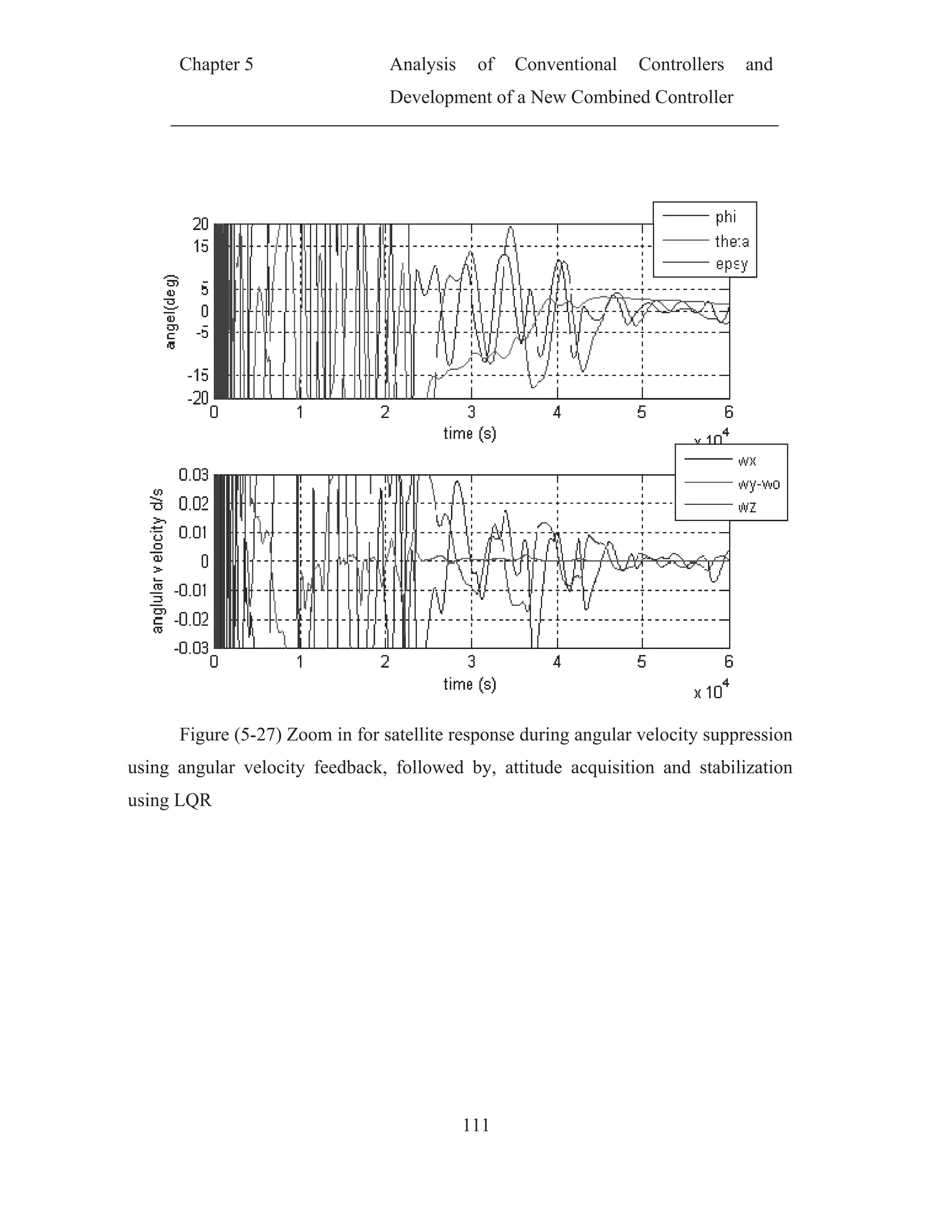
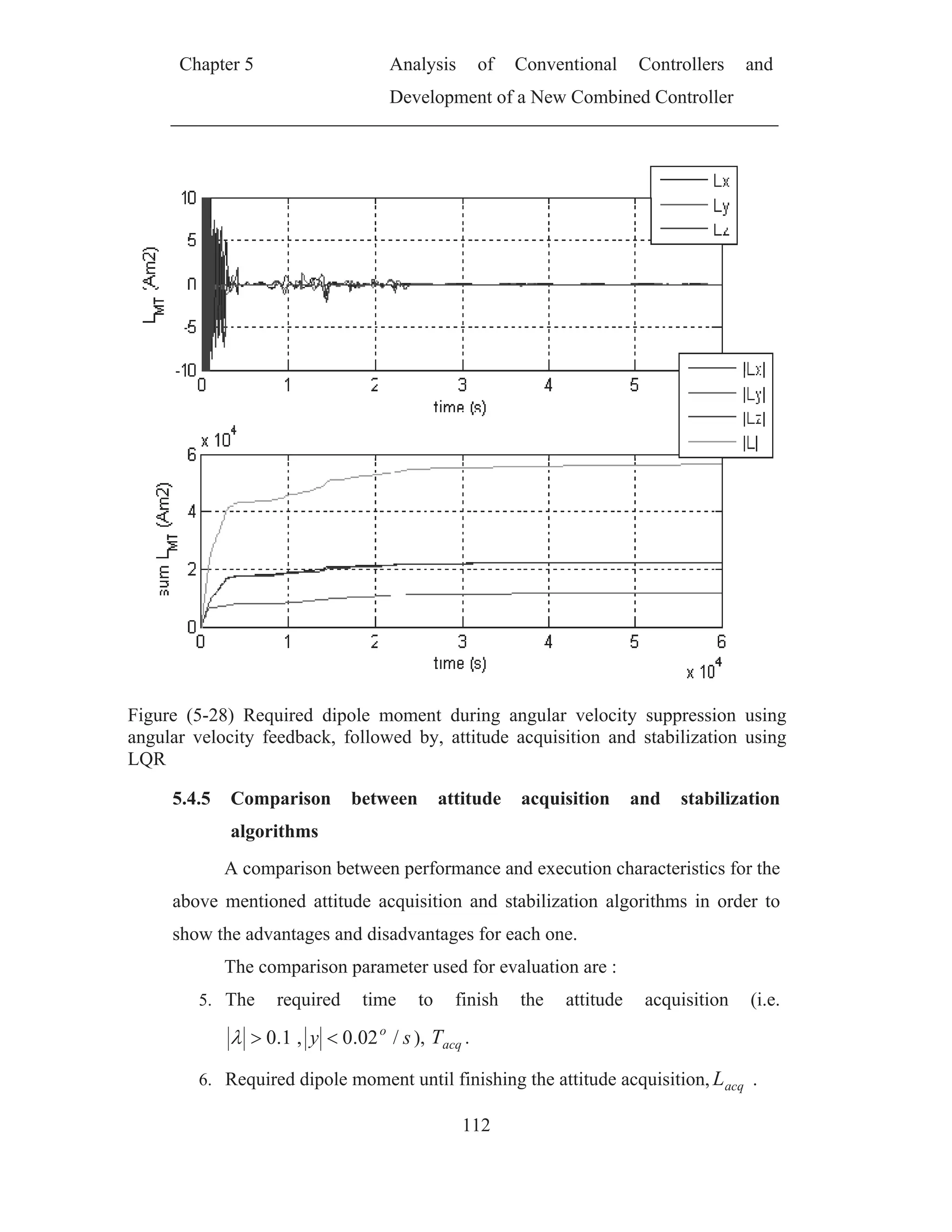
![Chapter 5 Analysis of Conventional Controllers and
Development of a New Combined Controller
113
7. The total dipole moment required during 10 orbital period totL
8. The steady stat error for angels and angular velocity ssss EE , .
9. The calculation time for one cycle of the algorithm calT
For the calculation time for one cycle of the algorithm the following
environments was used for the evaluation.
Algorithm was developed and run using Borlandc 3.11.
Run on PC with Pentium (D) CPU 3.40 GHz. With 1 GB RAM
Used operating system XP SP2
The following table summarizes the comparison results
Table 5-3the comparison result between attitude acquisition and stabilization
algorithms
PD-like controller
Sliding Mode
controller
LQR
acqT [s] 5,754 9,609 25,340
acqL [Am2
] 5.658e4 6.259e4 5.480e4
calT [s] 4.451e-6 6.091e-6 3.539e-3
totL [Am2
/s] 12.84e4 12.99e4 5.652e4
ssE [deg.] ±10 ±7 ±4
ssE [deg./s] ±0.013 ±0.011 ±0.008
Results conclusion
The above comparison table showed that
1. PD-like controller is the simplest (i.e. calculation time is the smallest
one ) algorithm and could achieve attitude acquisition very fast but
needs large dipole moments during stabilization and give low accuracy
2. the LQR is very useful to save the consumed power by MT specially
during the stabilization period and give very high accuracy but needs
high calculation resources and it is not suitable for attitude acquisition.](https://image.slidesharecdn.com/spacecraftattitudemagneticcontroller-150428041306-conversion-gate02/75/Spacecraft-attitude-magnetic-controller-132-2048.jpg)
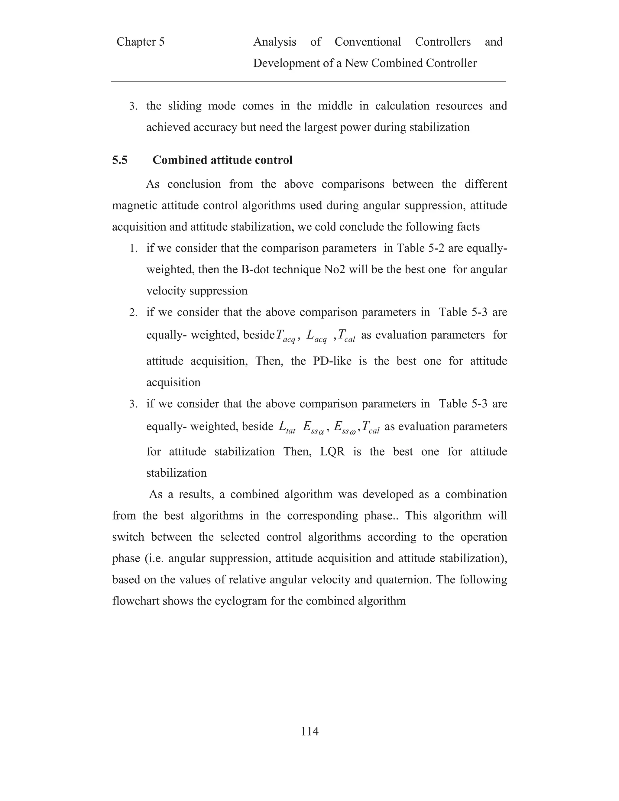
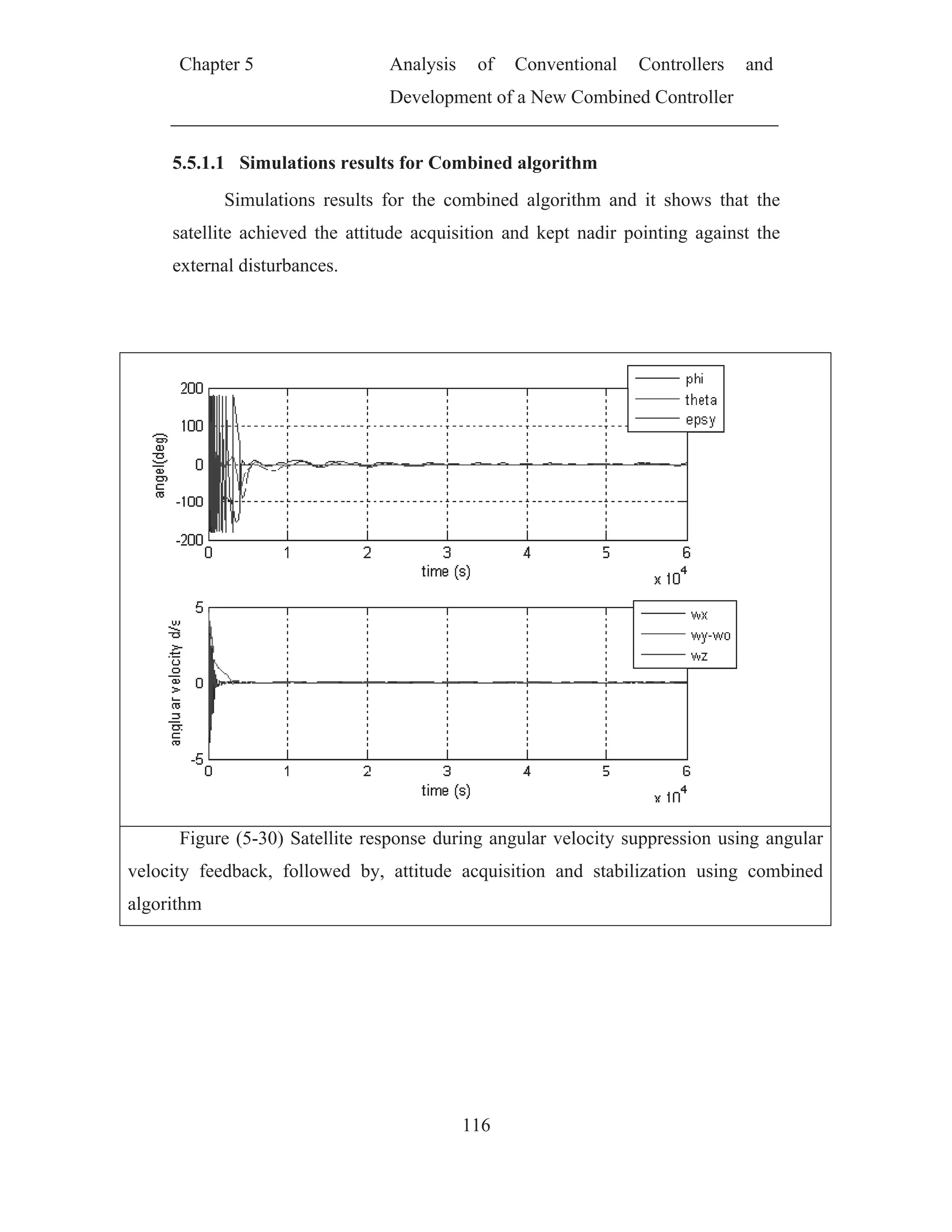

![Ch
Fig
using ang
using com
hapter 5
gure (5-32
gular veloc
mbined alg
The ab
Table 5
2) Require
city feedba
orithm
ove simula
5-4 the com
Comparis
aT
acL
totL
T
ssE
ssE
Analy
Devel
d dipole m
ack, follow
ation result
mbined alg
son Parame
acqT [s]
cq [Am2
]
[Am2
/s]
calT [s]
s [deg.]
[deg./s]
ysis of
lopment of
118
moment du
wed by, at
ts could be
orithms res
eter
Conventio
f a New Co
uring angu
ttitude acq
e surmised
sults
Va
5,8
4.44
4.4
4.99e-6 /
±
±0.0
onal Con
ombined Co
ular veloci
quisition an
in the follo
alue
807
43e4
49e4
/ 3.539e-3
±3
0075
ntrollers a
ontroller
ity suppres
nd stabiliz
owing table
and
ssion
ation
e.](https://image.slidesharecdn.com/spacecraftattitudemagneticcontroller-150428041306-conversion-gate02/75/Spacecraft-attitude-magnetic-controller-137-2048.jpg)
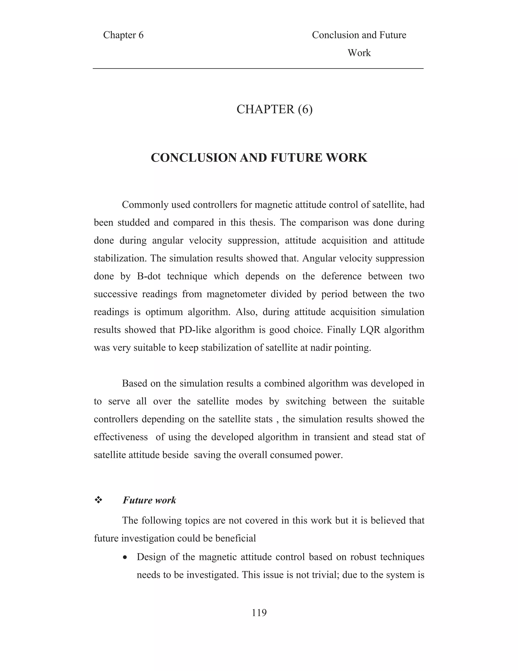
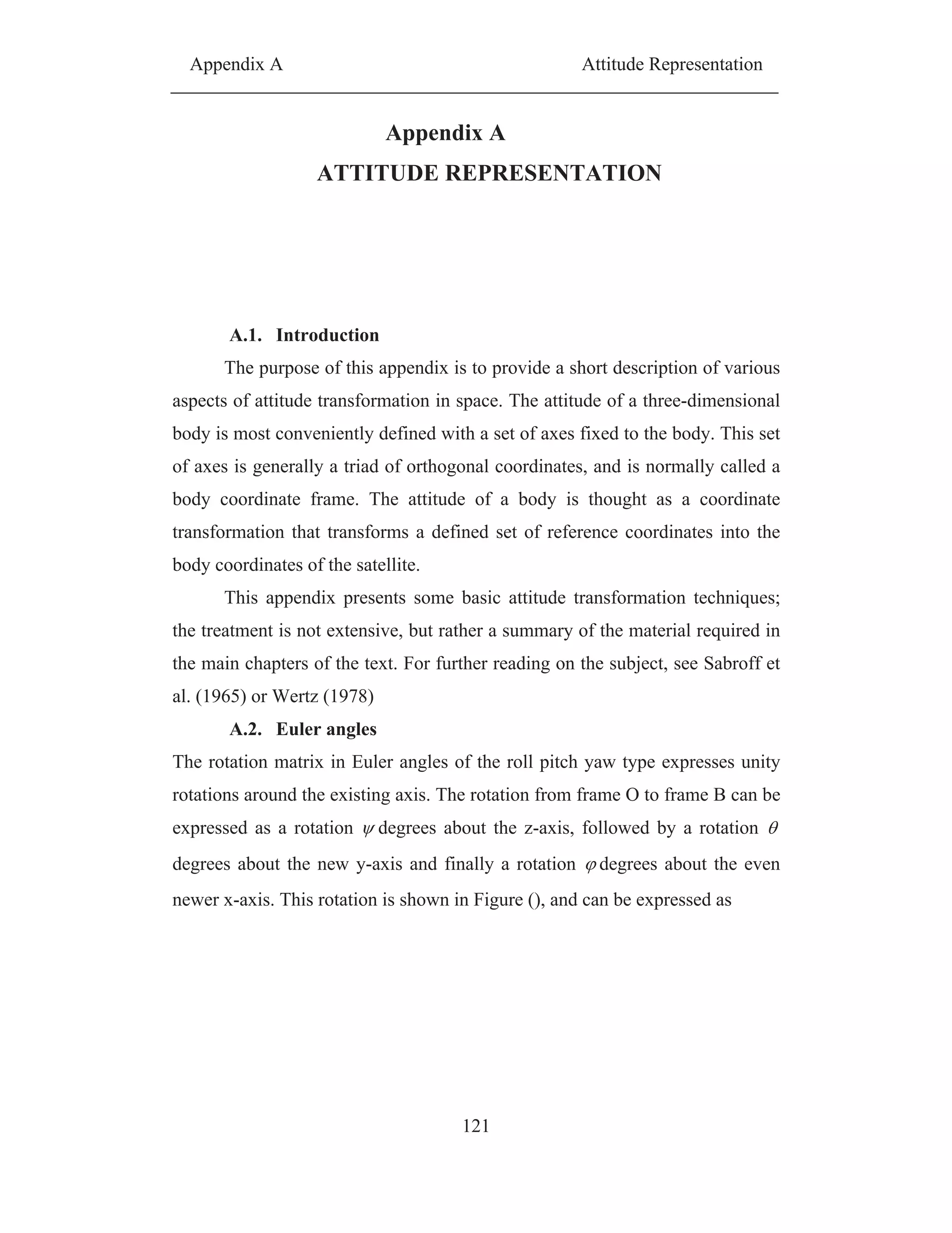
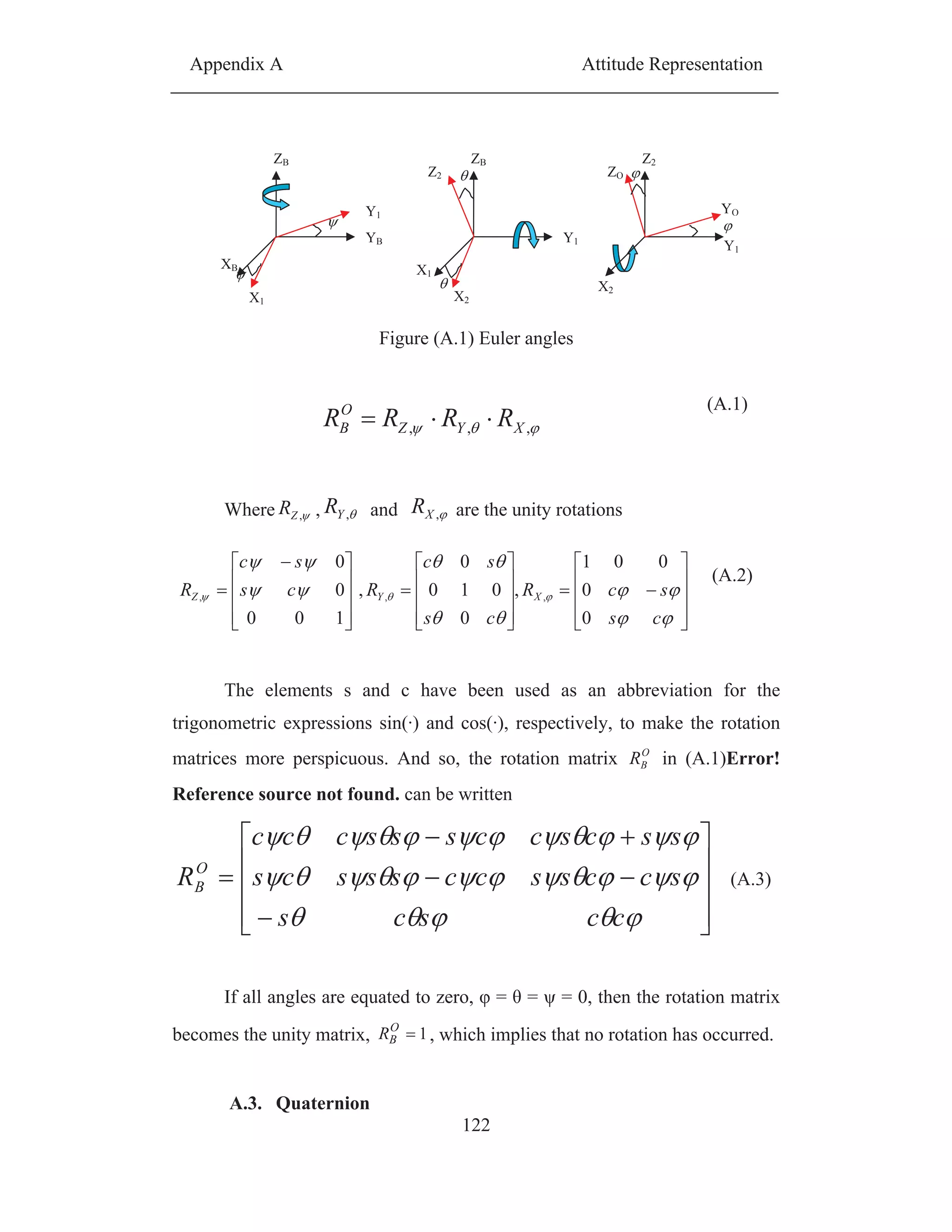
![Appendix A Attitude Representation
123
Quaternion is one of many ways to represent attitude. The quaternion
has the advantage of being without singularities for all attitudes.
A quaternion q is defined by its four vector elements 0 q1, 1 q2, 2 q3
and 3 q4, as
3
2
1
0
3210 kji
(A.4)
where ji, i, j and k k are hyper imaginary numbers satisfying
1222
kji (A.5)
kjiij (A.6)
ikjjk (A.7)
jikki (A.8)
The four parameters of a quaternion are subject to the constraint that
1
2
3
2
2
2
1
2
0 (A.9)
Which means that the quaternion has three degrees of freedom,
corresponding to the minimum set of parameters needed for attitude
representation [Wertz, 1978].
The 1st
element 0 of the quaternion is named the scalar element, and
the 2nd
,3rd
and 4th
are the complex elements. The complex part of the
quaternion is written , hence a quaternion may be written
0
(A.10)
A rotation around a unit vectoru , is represented by the quaternion
2
sin
2
cos
u
(A.11)
The complex conjugate of the quaternion is defined as](https://image.slidesharecdn.com/spacecraftattitudemagneticcontroller-150428041306-conversion-gate02/75/Spacecraft-attitude-magnetic-controller-142-2048.jpg)
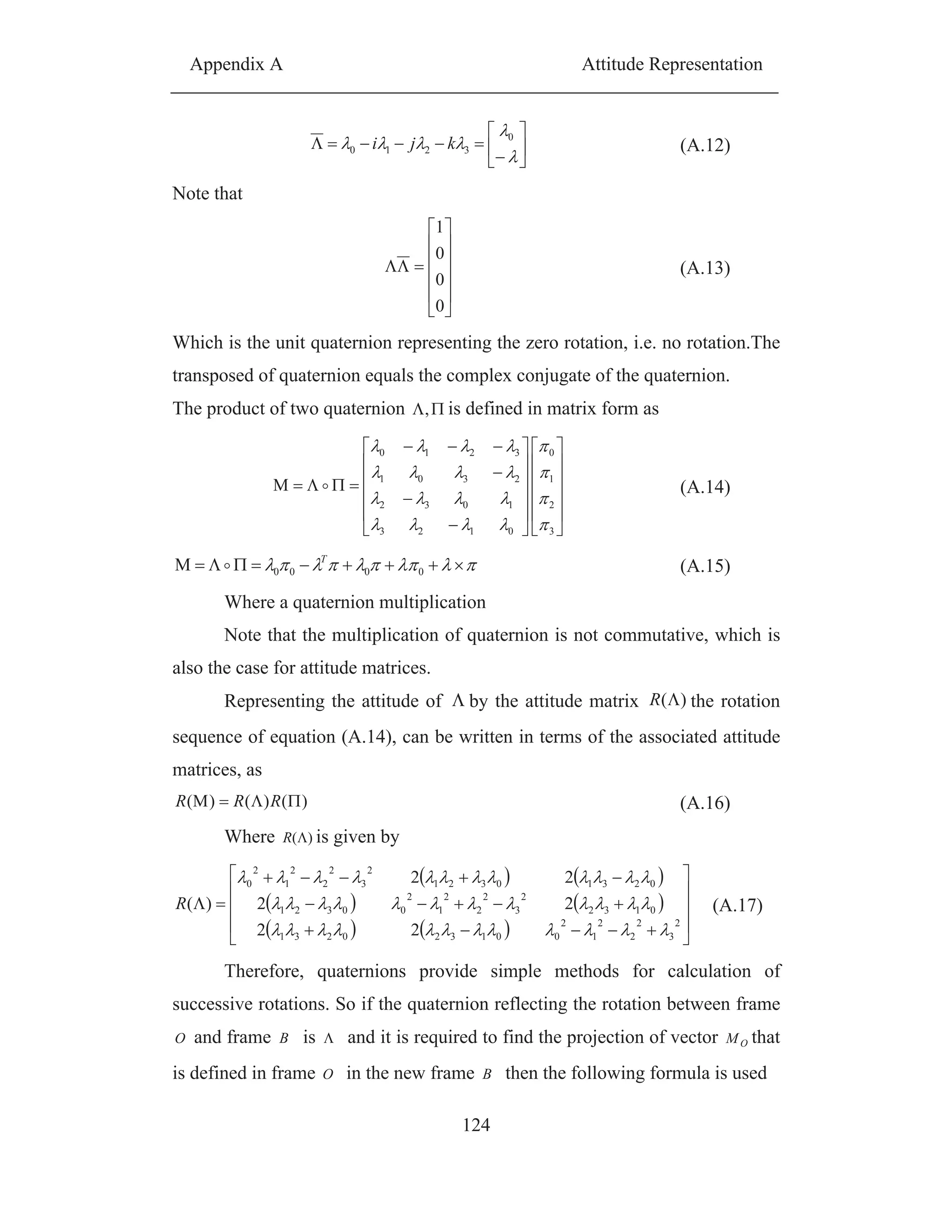
![Appendix A Attitude Representation
125
OOO
O
MMM
M
22
M
0
B
(A.18)
Note that the above formula for calculating BM gives the same results as
if the transformation matrixes defined in (A.15) as follows
OMR )(MB (A.19)
A.4. Direction Cosine Matrix
The basic three-axis attitude transformation is based on the direction
cosine matrix. Any attitude transformation in space is actually converted to this
essential form. In Figure ), the axes 1, 2, and 3 are unit vectors defining an
orthogonal, right-handed triad. This triad is chosen as the reference inertial
frame. Next, a similar orthogonal triad is attached to the center of mass of a
moving body, denned by the unit vectors u, v, and w,
Figure (A.2) Definition of the orientation of the satellite axes u.v.w in the
reference frame
In the context of Figure (A.2.1), we define the matrix [R] as follows:
321
321
321
][
www
vvv
uuu
R (A.20)
In this matrix, u1, u2, u3 are the components of the unit vector u along the
three axes 1,2, 3 of the reference orthogonal system: u=[u1 u2 u3]T
. In a similar
way, v and w have components v1, v2, v3 and w1, w2, w3 along the same
reference axes: v = [v1 v2 v3]T
and w = [w1 w2 w3]T
. The direction cosine matrix
[R], also called the attitude matrix, has the important property of mapping](https://image.slidesharecdn.com/spacecraftattitudemagneticcontroller-150428041306-conversion-gate02/75/Spacecraft-attitude-magnetic-controller-144-2048.jpg)
![Appendix A Attitude Representation
126
vectors from the reference frame to the body frame. Suppose that a vector a
has components, in the reference frame: a = [a1 a2 a3]T
. The following matrix
vector multiplication In this matrix, u1, u2, u3 are the components of the unit
vector u along the three axes 1,2, 3 of the reference orthogonal system: u=[u1 u2
u3]T
. In a similar way, v and w have components v1, v2, v3 and w1, w2, w3 along
the same reference axes: v = [v1 v2 v3]T
and w = [w1 w2 w3]T
. The direction
cosine matrix [R], also called the attitude matrix, has the important property of
mapping vectors from the reference frame to the body frame. Suppose that a
vector a has components, in the reference frame: a = [a1 a2 a3]T
. The
following matrix vector multiplication.
w
v
u
B
a
a
a
a
a
a
www
vvv
uuu
aRa
3
2
1
321
321
321
][ (A.21)
Where Ba is the vector a mapped into the body frame.
Since u is a unit vector, it follows that the scalar product ua is the
component ua of the vector a along the unit vectoru . By the same reasoning,
the components of the vector a on the remaining unit vectors of the body triad
are va and wa
Some basic properties of the matrix [R] may be stated as follows.
Each of its elements is the cosine of the angle between a body unit vector and a
reference axis; its name is derived from this property.
1. Each of the vectors u, v, w are vectors with unit length; hence:
,1,1,1
3
1
2
3
1
2
3
1
2
i
i
i
i
i
i wvu (A.22)
The unit vectors ,,, wvu are orthogonal to each other; hence
,0,0,0
3
1
3
1
3
1 i
ii
i
ii
i
ii wvwuvu (A.23)
The relationships in (2) and (3) lead to the useful identity 1T
RR , or
1
RR T
. of course, transposition of a matrix is a much simpler process than inversion
of the same matrix.](https://image.slidesharecdn.com/spacecraftattitudemagneticcontroller-150428041306-conversion-gate02/75/Spacecraft-attitude-magnetic-controller-145-2048.jpg)
![Appendix A Attitude Representation
127
It is well known that )(det wvuR since wvu ,, form a cubic orthogonal triad, it
follows that 1]det[R . Thus
B
T
aRa
(A.24)](https://image.slidesharecdn.com/spacecraftattitudemagneticcontroller-150428041306-conversion-gate02/75/Spacecraft-attitude-magnetic-controller-146-2048.jpg)
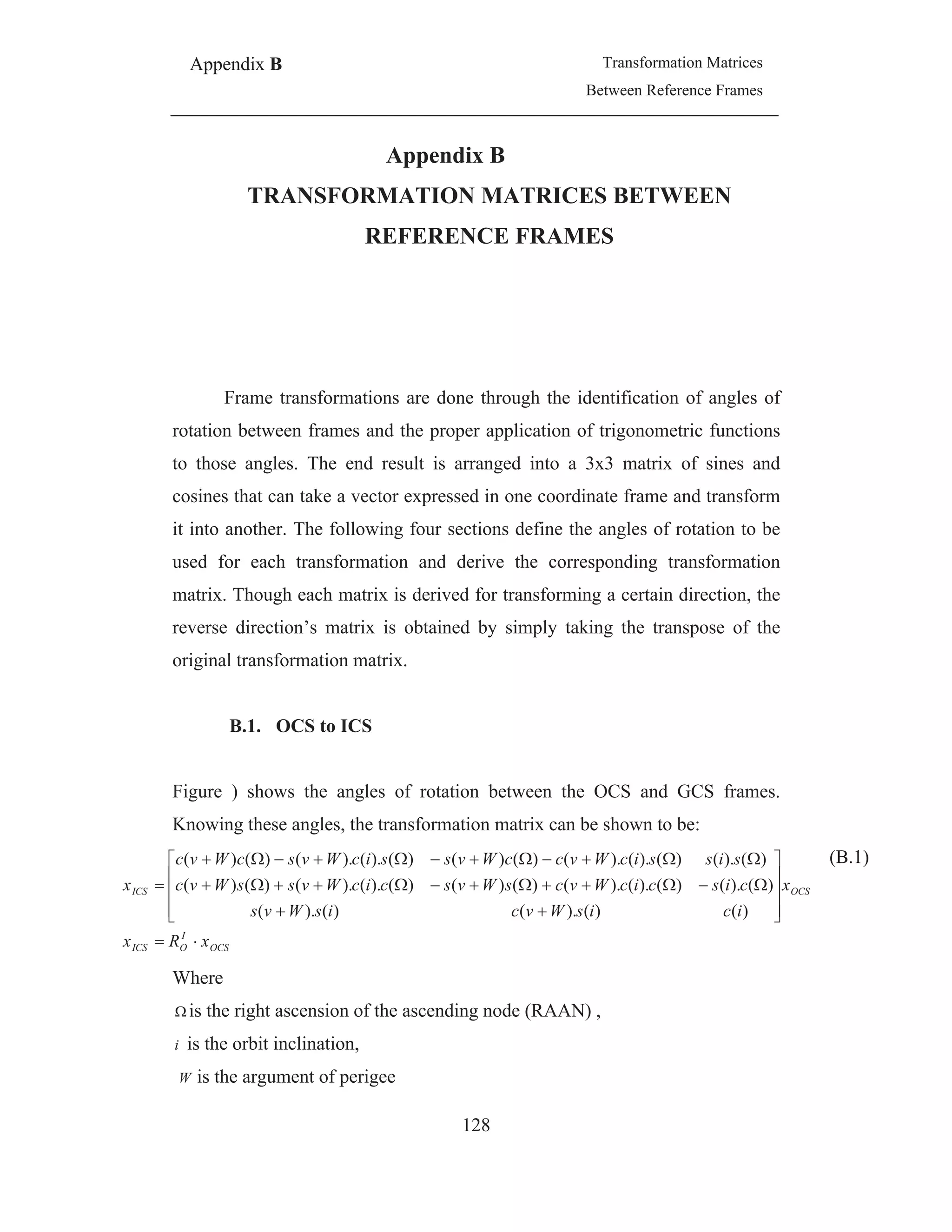

![Reference
132
References
[1]http://ocw.mit.edu/NR/rdonlyres/Aeronautics-and-Astronautics/16-892JFall-
2004/5E921686-B4CD-4949-A0D3-9A2DD6E4D6C/0/01010
wk1_framing.pdf
[2] http://integral.esa.int/Publications/taormina_final_short2.PDF
[3]Anil K. Maini and Varsha Agrawal "Satellite technology principals and
applications" John Wiley & Sons Ltd Publishers 2007
[4] Wertz, James R. and Wiley J. Larson (eds.) “Space Mission Analysis and
Design, 3rd Ed.” Microcosm Press/Kluwer Academic Publishers 1999
[5] http://www.williamcraigcook.com/satellite/anatomy.html.
[6] Prof. R. H. "Tolson Space Flight Mechanicsa.k.a. Astrodynamics" , fall
2005 ,NC stat university , USA
[7]William E. Wieles "satellite dynamics, 2nd Ed" McGraw-Hill companies
Inc.1997
[8] http://www.inetdaemon.com/tutorials/telecom/satellite/orbits.shtml
[9] http://en.wikipedia.org/wiki/Medium_Earth_Orbit
[10] John S. Eterno, Robert O. Zermuehlen, Harold F Zimbelman. “Attitude
Determination and Control.” SPACE MISSION ANALYSIS AND DESIGN.
edited by Wiley J. Larson and James R. Wertz, second edition, Space
Technology Series, Microcosm, Inc. & Kluwer Academic Publishers, 1992,
pp. 340-366.
[11] Challa, M., Natanson, G., Deutschmann,J., and Galal, K., “A PC-Based
Magnetometer-Only Attitude and Rate Determination System for Gyroless
Satellite”, presented at the GSFC FDD Flight Mechanics. Estimation Theory
Symposium 1995. Paper No. 07, NASA Goddard Space Flight Center,
Greenbelt, Maryland, May 16-18, , pp.83-96, 1995](https://image.slidesharecdn.com/spacecraftattitudemagneticcontroller-150428041306-conversion-gate02/75/Spacecraft-attitude-magnetic-controller-151-2048.jpg)
![Reference
133
[12] Marcel J. Sidi. "Satellite Dynamics and Control, A Practical Engineering
Approach ".Cambridge Aerospace Series. Cambridge University Press,
Cambridge, 1997.
[13] Goldstein.H. ,classical mechanics reading , MA : Addison-Wesley , 1964
[14] Thomson .W.T, introduction to space dynamics , New York , Dover, 1986
[15] J ames R. Wertz, editor. "Satellite Attitude Determination and Control."
Kluwer Academic Publishers, Dordrecht, 2000.
[16] D. Lebedev, A. Tkachenko ” Magnetic Attitude Control System for Low-
Earth”, Multibody System Dynamics,2001.
[17]Beletsky, V.V., “Libration of a Satellite”, Transactions: Artificial Satellites
of the Earth, Moscow, USSR Academy of Sciences, Issue 3, 1959
[18] Wisniewski, R., & Blanke, M. (1999). Fully magnetic attitude control for
satellite subject to gravity gradient. Automatica, 35(7), p.1201–1214.
[19]Jan Tomy,”magnetic attitude control for satellites” , 43rd
IEEE Conference
on Decision and Control 2004, Atlantis, Paradise Island, Bahamas
[20] Wisniewski, R. "Satellite Attitude Control Using Only Electromagnetic
Actuation", Ph.D.Thesis, Aalborg University, Denmark, 1996
[21] Enrico Silani, Marco Lovera " Magnetic satellite attitude control: a survey
and some new results", Control Engineering Practice,2003
[22] Carlo Arduini and Paolo Baiocco. "Active Magnetic Damping Attitude
Control for Gravity Gradient Stabilized Spacecraft". Journal of Guidance
Control and Dynamics, 1997.
[23] Daniel Vernon Guerrant” Design And Analysis of Fully Magnetic Control
For Picosatellite Stabilization” Master thesis , California Polytechnic State
University,2005
[24] Marco Lovera and Alessandro Astolfi “Global magnetic attitude control
of satellite”, 43rd
IEEE Conference on Decision and Control 2004, Atlantis,
Paradise Island, Bahamas](https://image.slidesharecdn.com/spacecraftattitudemagneticcontroller-150428041306-conversion-gate02/75/Spacecraft-attitude-magnetic-controller-152-2048.jpg)
![Reference
134
[25] Kjell Magne Fauske” Ncube Attitude Control”, Department of
Engineering Cybernetics,NTNU, 2002
[26] Saiijay P. Bhat & Ajit S. Dhain “Controllability of Satellite Attitude
Under Magnetic Actuation “ Proceedings of the 42nd IEEE , Conference on
Decision and Control Maui, Haraii USA, 2003
[27]Kristiansen, R.” Attitude controll of mini satellite”. Master’s thesis, NTNU
,2000
[28] Jens Gießelmann "Development of an Active Magnetic Attitude
Determination and Control System for Picosatellites on highly inclined
circular Low Earth Orbits" Master thesis , School of Aerospace, Mechanical
and Manufacturing Engineering Science, Engineering and Technology
Portfolio , RMIT University, Germany, 2006](https://image.slidesharecdn.com/spacecraftattitudemagneticcontroller-150428041306-conversion-gate02/75/Spacecraft-attitude-magnetic-controller-153-2048.jpg)