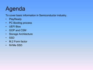
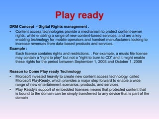
Agenda
To cover basic information in Semiconductor industry.
• PlayReady
• PC Booting process
• UEFI Bios
• GOP and CSM
• Storage Architecture
• SSD
• M.2 Form factor
• NVMe SSD
Play ready
DRM Concept - Digital Rights management .
• Content access technologies provide a mechanism to protect content-owner
rights, while enabling a range of new content-based services, and are a key
enabling technology for mobile operators and handset manufacturers looking to
increase revenues from data-based products and services.
Example :
Each license contains rights and restrictions. . For example, a music file license
may contain a "right to play" but not a "right to burn to CD" and it might enable
these rights for the period between September 1, 2008 and October 1, 2008
Reason to Come Play ready Technology
• Microsoft invested heavily to create new content access technology, called
Microsoft PlayReady, which provides a major step forward to enable a wide
range of new entertainment scenarios, products, and services.
• Play Ready's support of embedded licenses means that protected content that
is bound to the domain can be simply transferred to any device that is part of the
domain
The Microsoft PlayReady Ecosystem
Boot Process Steps
Booting is the process of loading OS from Hard disk to Memory
• Power ON
• System clock – Initialize CPU
• CPU initialize System ROM Bios
• POST
• Again CPU Initialized Fully
• BIOS looks for OS to load
• It looks for CMOS Chip (Maintains Boot order)
• If a valid Bootable Device found , Checks for MBR
• MBR contains active primary partition
• BIOS load Boot loader into the MBR (Boot loader is the small program )
• It tells where to find out the beginning of OS .
• Bootloader initialize and copies all necessary files into the memory .
• OS takes control of the boot process
• Load all the Device drivers
• Finally Enters into OS
Legacy & UEFI Booting Process
• BIOS Firmware - maintains a list of installed storage devices that may be bootable
• POST – Power on Self test .
• Firmware loads the first sector of each of the storage targets into memory and scans it for a valid
Master Boot Record (MBR)
• If a valid MBR is found, the firmware passes execution to the boot loader code found in the MBR
• A boot loader, also called a boot manager, is a small program that places the operating system
(OS) of a computer into memory.
• UEFI boot is the boot process used by UEFI firmware
• The firmware maintains a list of valid boot volumes called EFI Service Partitions
• MBR can store only one boot loader whereas GPT has a separate dedicated EFI System
Partition(ESP) for storing multiple boot loaders.
• This is very helpful if you have two or more operating systems which require different boot
loaders.
BIOS
Firmware POST
Load and
Execute
Optional ROM
MBR
Boot
Loader
Pre OS
LEGACY BIOS
UEFI BIOS
BIOS
Firmware POST
Load and
Execute
Optional ROM
GPT /
MBR
Boot
Loader
Pre OS
UEFI BIOS
1. UEFI is programmable, original equipment manufacturer (OEM) developers can add
applications and drivers, allowing UEFI to function as a lightweight operating system.
2. The ultimate difference between UEFI and legacy is the process that the firmware
uses to find the boot target.
3.Uses GPT instead of MBR
4.Replaces VBIOS by GOP
5. Written in C language
Continues……
6. Visual more . UEFI has the ability to run standalone UEFI applications
7. Ability to boot from large disks (over 2 TB) with a GUID Partition Table . Max 9 Zeta bytes
8. Flexible pre-OS environment, including network capability .
9. Backward and forward compatibility
10.EFI defines two types of services:
Boot services
Boot services are available only while the firmware owns the platform
include text and graphical consoles on various devices, and bus, block and
file services
Runtime services
Runtime services are still accessible while the operating system is running
date, time and NVRAM access
12.The UEFI 2.3.1 Errata C specification (or higher) defines a protocol known as secure boot,
which can secure the boot process by preventing the loading of drivers or OS loaders that
are not signed with an acceptable digital signature
GOP and CSM
Difference between UEFI and Legacy
S.no LEGACY BIOS UEFI BIOS
1
BIOS uses the Master Boot Record(MBR)
partitioning scheme UEFI uses the GUID Partition Table (GPT)
2 Max partition size in MBR is ~2TB Maximum partition UEFI it is ~9 ZetaBytes
3 MBR can have at max 4 primary partition GPT can have 128 Partitions
4 MBR can store only one boot loader GPT has a separate dedicated EFI System
Partition(ESP) for storing multiple boot loaders
5 No Secure boot UEFI offers secure boot
6 Used VBIOS for Graphics output Used GOP for Graphics output
7 Assembly language C- language
8 Take long time to boot Fast POST and Boot
9 Take time delay from S States Faster resumes from S states Sleep / Hibernate
GOP : Graphics output protocol
What is a video BIOS?
• A video BIOS or VBIOS is the Basic Input Output System (BIOS) of a graphics card or
the integrated graphics controller in a computer.
• INT 10h, INT 10H or INT 16 is the BIOS interrupt call 10hex, to handle setting the
video mode, character and string output, and graphics primitives (reading and
writing pixels in graphics mode)
GOP Functions
• The ultimate goal of GOP is to replace legacy VGA BIOS and eliminate VGA HW
functionality.
• The Graphics Output Protocol (GOP) is enabled by UEFI driver to support graphic
console output in the pre-OS phase.
• Graphics Output Protocol (GOP) is a protocol defined under the UEFI 2.1
Specification and is a replacement for legacy Video BIOS
• GOP provides software abstraction to allow pixels to be directly drawn to the frame
buffer. GOP is designed to support the basic needs of graphics output prior to
Operating System boot
Questions :
Can the legacy VBIOS and the GOP Driver co-exist in a single
SBIOS image?
Yes. The legacy VBIOS and the GOP Driver can co-exist in single
SBIOS image. However, only one driver can be loaded at a given
moment, since only one driver can interact with the graphics
hardware.
Do we require separate VBT for legacy VBIOS & GOP Driver?
Yes. With the legacy VBIOS, VBT is baked-in (.DAT). With the GOP
Driver, VBT is a separate, standalone package (VBT.bin).
What is the size of GOP Driver?
The current size of the GOP Driver is ~34 KB. The VBT.bin is ~4KB.
Storage Host Interface
 Serial ATA (SATA)
 SAS - Serial attached SCSI (generally found on servers)
 PCI Express
 Fibre Channel (almost exclusively found on servers)
 USB
 Parallel ATA (IDE) interface (mostly replaced by SATA)
SSD:
Nand based SSD :
•
1. Use non-volatile NAND flash memory
2. Ability to retain the data without a constant power supply
3. Lower cost compared to DRAM
4. Flash memory SSDs are slower than DRAM solutions.
DRAM based SSD :
1.Based on volatile memory such as DRAM
2. Internal battery or an external AC/DC adapter is needed to hold the data .
3. ultrafast data access
4. Primarily to accelerate applications
5.Higher cost compared to NAND flash memory
SSD Architecture
M.2 Sata
• M.2, formerly known as the Next Generation Form Factor (NGFF)
• Computer bus interfaces provided through the M.2 connector are PCI Express 3.0 (up
to four lanes), Serial ATA 3.0, and USB 3.0
• The M.2 small form factor applies to many add-in card types, such as Wi-Fi,
Bluetooth, satellite navigation, Near Field Communication (NFC), digital radio,
Wireless Gigabit Alliance (WiGig), Wireless WAN (WWAN) and Solid-State Drives
(SSDs).
• mSATA Relatively small size, typically 16 GB or 32 GB. mSATA was used to cache the hard
drive. Used as cache Memory.
• mSATA was unable to be scaled up to 1TB capacities
Questions :
Is an M.2 SSD the same as an mSATA SSD?
No, they are different. M.2 supports both SATA and PCIe storage interface options, while
mSATA is SATA only. Physically, they look different and cannot be plugged into the same system
connectors.
M.2 SATA SSD vs. M.2 PCIe SSDs
• M.2 is the physical form factor.
• SATA and PCIe refer to the storage interface, with the primary difference being
performance and the protocol (language) spoken by the M.2 SSD
• The M.2 specification was designed to accommodate both a SATA and PCIe
interface for SSDs.
• M.2 SATA SSDs will use the same controller currently available on typical 2.5 in
SATA SSDs.
• M.2 PCIe SSDs will use a controller specifically designed to support the PCIe
protocol.
• An M.2 SSD can support only one protocol, but some systems have M.2 sockets
that can support either SATA or PCIe.
Questions
Does an M.2 SSD support both SATA and PCIe?
No. An M.2 SSD will support either SATA or PCIe, but not both at the
same time. In addition, system board sockets will be designated by
manufacturers to support either SATA, PCIe or, in some cases, both.
The PCIe interface is faster, as the SATA 3.0 specification is limited to
~600MB/s maxi There is also a new PCIe gen 3 technology that will, with x4
speeds of up to 4000MB/s
Are M.2 SSDs hot-pluggable?
• No, M.2 SSDs were not designed to be hot-pluggable. Please install and
remove M.2 SSDs when the system is powered off.
M.2 Architecture
NVMe – Basic info
• Improving performance is never just about hardware. Need efficient
Software .
• NVMe stands for Non-Volatile Memory Express and is simply a protocol for
getting flash memory to operate as an SSD via PCIe. It implies nothing
about the form factor.
• In fact, some 2.5" drives *are* NVMe and operate via a U.2 connection
(which can be adapted from an M.2 port via a special M.2 card).
• AHCI is more optimized for high latency rotating media than low latency
non-volatile storage. As a result AHCI can't take full advantage of SSDs.
• The result is NVMe, short for Non-Volatile Memory Express. It was
developed by an industry consortium with over 80 members and the
development was directed by giants like Intel, Samsung, and LSI.
Continues ……
• NVMe is built specifically for SSDs and as we move to future memory
technologies (i.e. RRAM and MRAM enter the storage market before
2020).
• NVMe or Non-Volatile Memory Host Controller Interface Specification
(NVMHCI) technology. NVMe is set to replace the AHCI (Advanced
Host Controller Interface) technology that came out in 2004
• NVMe reduces latency and supports multiple queues at higher queue
depths
• NVMe allows multiple CPU queues with deep queue depths (up to 64K
outstanding IOs)
Types of NVMe SSD
Interface: PCIExpress, NVMe Interface: M.2 , NVMe
Interface: 2.5” U.2 , NVMe
Used Words
• POST - Power ON Self Test
• BIOS - basic input/output system
• SBIOS - System BIOS
• CMOS - Complementary metal–oxide–semiconductor
• MBR - Master Boot Record
• UEFI - Unified Extensible Firmware Interface
• ESP - EFI System Partition
• GPT - GUID Partition Table
• GUID - Globally Unique Identifier
• GOP - Graphics Output Protocol
• VBIOS - Video BIOS
• OEM - Original equipment manufacturer
• CSM - Compatibility Support Module
• NVRAM - Non-volatile random-access memory
• DRAM - Dynamic random-access memory
• RRAM - Resistive random-access memory
• MRAM - Magneto resistive random-access memory
• DXE - Driver Execution Engine
• VBT - Video Bios Table
• AHCI - Advanced Host Controller Interface
Presented by Prabu M
UST Global

Sorage & pc booting ppt prabu

  • 1.
    Agenda To cover basicinformation in Semiconductor industry. • PlayReady • PC Booting process • UEFI Bios • GOP and CSM • Storage Architecture • SSD • M.2 Form factor • NVMe SSD
  • 2.
    Play ready DRM Concept- Digital Rights management . • Content access technologies provide a mechanism to protect content-owner rights, while enabling a range of new content-based services, and are a key enabling technology for mobile operators and handset manufacturers looking to increase revenues from data-based products and services. Example : Each license contains rights and restrictions. . For example, a music file license may contain a "right to play" but not a "right to burn to CD" and it might enable these rights for the period between September 1, 2008 and October 1, 2008 Reason to Come Play ready Technology • Microsoft invested heavily to create new content access technology, called Microsoft PlayReady, which provides a major step forward to enable a wide range of new entertainment scenarios, products, and services. • Play Ready's support of embedded licenses means that protected content that is bound to the domain can be simply transferred to any device that is part of the domain
  • 3.
  • 4.
    Boot Process Steps Bootingis the process of loading OS from Hard disk to Memory • Power ON • System clock – Initialize CPU • CPU initialize System ROM Bios • POST • Again CPU Initialized Fully • BIOS looks for OS to load • It looks for CMOS Chip (Maintains Boot order) • If a valid Bootable Device found , Checks for MBR • MBR contains active primary partition • BIOS load Boot loader into the MBR (Boot loader is the small program ) • It tells where to find out the beginning of OS . • Bootloader initialize and copies all necessary files into the memory . • OS takes control of the boot process • Load all the Device drivers • Finally Enters into OS
  • 5.
    Legacy & UEFIBooting Process • BIOS Firmware - maintains a list of installed storage devices that may be bootable • POST – Power on Self test . • Firmware loads the first sector of each of the storage targets into memory and scans it for a valid Master Boot Record (MBR) • If a valid MBR is found, the firmware passes execution to the boot loader code found in the MBR • A boot loader, also called a boot manager, is a small program that places the operating system (OS) of a computer into memory. • UEFI boot is the boot process used by UEFI firmware • The firmware maintains a list of valid boot volumes called EFI Service Partitions • MBR can store only one boot loader whereas GPT has a separate dedicated EFI System Partition(ESP) for storing multiple boot loaders. • This is very helpful if you have two or more operating systems which require different boot loaders. BIOS Firmware POST Load and Execute Optional ROM MBR Boot Loader Pre OS LEGACY BIOS UEFI BIOS BIOS Firmware POST Load and Execute Optional ROM GPT / MBR Boot Loader Pre OS
  • 6.
    UEFI BIOS 1. UEFIis programmable, original equipment manufacturer (OEM) developers can add applications and drivers, allowing UEFI to function as a lightweight operating system. 2. The ultimate difference between UEFI and legacy is the process that the firmware uses to find the boot target. 3.Uses GPT instead of MBR 4.Replaces VBIOS by GOP 5. Written in C language
  • 7.
    Continues…… 6. Visual more. UEFI has the ability to run standalone UEFI applications 7. Ability to boot from large disks (over 2 TB) with a GUID Partition Table . Max 9 Zeta bytes 8. Flexible pre-OS environment, including network capability . 9. Backward and forward compatibility 10.EFI defines two types of services: Boot services Boot services are available only while the firmware owns the platform include text and graphical consoles on various devices, and bus, block and file services Runtime services Runtime services are still accessible while the operating system is running date, time and NVRAM access 12.The UEFI 2.3.1 Errata C specification (or higher) defines a protocol known as secure boot, which can secure the boot process by preventing the loading of drivers or OS loaders that are not signed with an acceptable digital signature
  • 8.
  • 9.
    Difference between UEFIand Legacy S.no LEGACY BIOS UEFI BIOS 1 BIOS uses the Master Boot Record(MBR) partitioning scheme UEFI uses the GUID Partition Table (GPT) 2 Max partition size in MBR is ~2TB Maximum partition UEFI it is ~9 ZetaBytes 3 MBR can have at max 4 primary partition GPT can have 128 Partitions 4 MBR can store only one boot loader GPT has a separate dedicated EFI System Partition(ESP) for storing multiple boot loaders 5 No Secure boot UEFI offers secure boot 6 Used VBIOS for Graphics output Used GOP for Graphics output 7 Assembly language C- language 8 Take long time to boot Fast POST and Boot 9 Take time delay from S States Faster resumes from S states Sleep / Hibernate
  • 10.
    GOP : Graphicsoutput protocol What is a video BIOS? • A video BIOS or VBIOS is the Basic Input Output System (BIOS) of a graphics card or the integrated graphics controller in a computer. • INT 10h, INT 10H or INT 16 is the BIOS interrupt call 10hex, to handle setting the video mode, character and string output, and graphics primitives (reading and writing pixels in graphics mode) GOP Functions • The ultimate goal of GOP is to replace legacy VGA BIOS and eliminate VGA HW functionality. • The Graphics Output Protocol (GOP) is enabled by UEFI driver to support graphic console output in the pre-OS phase. • Graphics Output Protocol (GOP) is a protocol defined under the UEFI 2.1 Specification and is a replacement for legacy Video BIOS • GOP provides software abstraction to allow pixels to be directly drawn to the frame buffer. GOP is designed to support the basic needs of graphics output prior to Operating System boot
  • 11.
    Questions : Can thelegacy VBIOS and the GOP Driver co-exist in a single SBIOS image? Yes. The legacy VBIOS and the GOP Driver can co-exist in single SBIOS image. However, only one driver can be loaded at a given moment, since only one driver can interact with the graphics hardware. Do we require separate VBT for legacy VBIOS & GOP Driver? Yes. With the legacy VBIOS, VBT is baked-in (.DAT). With the GOP Driver, VBT is a separate, standalone package (VBT.bin). What is the size of GOP Driver? The current size of the GOP Driver is ~34 KB. The VBT.bin is ~4KB.
  • 12.
    Storage Host Interface Serial ATA (SATA)  SAS - Serial attached SCSI (generally found on servers)  PCI Express  Fibre Channel (almost exclusively found on servers)  USB  Parallel ATA (IDE) interface (mostly replaced by SATA) SSD: Nand based SSD : • 1. Use non-volatile NAND flash memory 2. Ability to retain the data without a constant power supply 3. Lower cost compared to DRAM 4. Flash memory SSDs are slower than DRAM solutions. DRAM based SSD : 1.Based on volatile memory such as DRAM 2. Internal battery or an external AC/DC adapter is needed to hold the data . 3. ultrafast data access 4. Primarily to accelerate applications 5.Higher cost compared to NAND flash memory
  • 13.
  • 14.
    M.2 Sata • M.2,formerly known as the Next Generation Form Factor (NGFF) • Computer bus interfaces provided through the M.2 connector are PCI Express 3.0 (up to four lanes), Serial ATA 3.0, and USB 3.0 • The M.2 small form factor applies to many add-in card types, such as Wi-Fi, Bluetooth, satellite navigation, Near Field Communication (NFC), digital radio, Wireless Gigabit Alliance (WiGig), Wireless WAN (WWAN) and Solid-State Drives (SSDs). • mSATA Relatively small size, typically 16 GB or 32 GB. mSATA was used to cache the hard drive. Used as cache Memory. • mSATA was unable to be scaled up to 1TB capacities Questions : Is an M.2 SSD the same as an mSATA SSD? No, they are different. M.2 supports both SATA and PCIe storage interface options, while mSATA is SATA only. Physically, they look different and cannot be plugged into the same system connectors.
  • 15.
    M.2 SATA SSDvs. M.2 PCIe SSDs • M.2 is the physical form factor. • SATA and PCIe refer to the storage interface, with the primary difference being performance and the protocol (language) spoken by the M.2 SSD • The M.2 specification was designed to accommodate both a SATA and PCIe interface for SSDs. • M.2 SATA SSDs will use the same controller currently available on typical 2.5 in SATA SSDs. • M.2 PCIe SSDs will use a controller specifically designed to support the PCIe protocol. • An M.2 SSD can support only one protocol, but some systems have M.2 sockets that can support either SATA or PCIe.
  • 16.
    Questions Does an M.2SSD support both SATA and PCIe? No. An M.2 SSD will support either SATA or PCIe, but not both at the same time. In addition, system board sockets will be designated by manufacturers to support either SATA, PCIe or, in some cases, both. The PCIe interface is faster, as the SATA 3.0 specification is limited to ~600MB/s maxi There is also a new PCIe gen 3 technology that will, with x4 speeds of up to 4000MB/s Are M.2 SSDs hot-pluggable? • No, M.2 SSDs were not designed to be hot-pluggable. Please install and remove M.2 SSDs when the system is powered off.
  • 17.
  • 18.
    NVMe – Basicinfo • Improving performance is never just about hardware. Need efficient Software . • NVMe stands for Non-Volatile Memory Express and is simply a protocol for getting flash memory to operate as an SSD via PCIe. It implies nothing about the form factor. • In fact, some 2.5" drives *are* NVMe and operate via a U.2 connection (which can be adapted from an M.2 port via a special M.2 card). • AHCI is more optimized for high latency rotating media than low latency non-volatile storage. As a result AHCI can't take full advantage of SSDs. • The result is NVMe, short for Non-Volatile Memory Express. It was developed by an industry consortium with over 80 members and the development was directed by giants like Intel, Samsung, and LSI.
  • 19.
    Continues …… • NVMeis built specifically for SSDs and as we move to future memory technologies (i.e. RRAM and MRAM enter the storage market before 2020). • NVMe or Non-Volatile Memory Host Controller Interface Specification (NVMHCI) technology. NVMe is set to replace the AHCI (Advanced Host Controller Interface) technology that came out in 2004 • NVMe reduces latency and supports multiple queues at higher queue depths • NVMe allows multiple CPU queues with deep queue depths (up to 64K outstanding IOs)
  • 20.
    Types of NVMeSSD Interface: PCIExpress, NVMe Interface: M.2 , NVMe Interface: 2.5” U.2 , NVMe
  • 21.
    Used Words • POST- Power ON Self Test • BIOS - basic input/output system • SBIOS - System BIOS • CMOS - Complementary metal–oxide–semiconductor • MBR - Master Boot Record • UEFI - Unified Extensible Firmware Interface • ESP - EFI System Partition • GPT - GUID Partition Table • GUID - Globally Unique Identifier • GOP - Graphics Output Protocol • VBIOS - Video BIOS • OEM - Original equipment manufacturer • CSM - Compatibility Support Module • NVRAM - Non-volatile random-access memory • DRAM - Dynamic random-access memory • RRAM - Resistive random-access memory • MRAM - Magneto resistive random-access memory • DXE - Driver Execution Engine • VBT - Video Bios Table • AHCI - Advanced Host Controller Interface
  • 22.
    Presented by PrabuM UST Global