SlideShare a Scribd company logo
1 of 1
Download to read offline
3D Television & Film
For more information on Sony training courses, seminars and sessions, contact :-
Sony Professional Education and Knowledge,
Sony Europe,
Jays Close,
Basingstoke,
Hampshire,
RG22 4SB,
United Kingdom.
Tel: +44 (0) 1256 483224
Fax: +44 (0) 1256 328767
Every effort has been made to ensure that the information contained on this poster is useful, accurate and correct.
However Sony Training Services cannot be held responsible for minor errors as a result of printing, advances in
technology, changes in standards, and improvements in working practices. If you find any errors or anomalies in
this poster please inform Sony Training Services at any of the contacts below. A complete list of changes from
previous versions is available from Sony Training Services. Correct to March 2010.
training.services@eu.sony.com
www.pro.sony.eu/training
R
Professional
Sony
Education
and
Knowledge
Version 3.0
Playing with the 3D image
With the 2 cameras set up correctly, the 3D image can be
modified to give the image more depth, or position it either
nearer or further away.
How to enhance a 3D shot
With the image shown here, shot with two cameras there are
two adjustments that can be made, the inter-axial distance,
or toe-in angle.
The cameras are placed a nominal 65mm
apart, parallel to one another. This produces
a reasonable 3D image, with a pleasing
amount of perceived depth for this scene.
The whole scene will be in front of the screen.
Standard 3D shot
When the distance between the two camera,
commonly referred to as the inter-axial
distance, is increased, the perceived depth
increases and the distance between object
in the scene appears to increase. However
care should be taken not to increase the
inter-axial distance too much. Close objects
will appear closer, but will not grow any larger.
The 3D illusion may break if the inter-axial
distance is too large. (See .)Depth Cues
Increased inter-axial distance
When the angle between the two cameras
is altered to point them slightly towards each
other, commonly referred to as the toe-in angle,
the perceived 3D image goes further into the
distance, even though the various objects
appear to be separated by the same distance.
Care should be taken not to push the 3D
scene back too far. Objects in the distance
may force eyes to diverge which may cause
eye strain. Excessive toe-in angles will also
introduce keystone errors which will need to be
corrected later. (See .)Camera Rig Errors
Altered toe-in angle
Note : Toe-in is performed on the camera rig and introduces
keystone errors. Convergence is a planar move with no
keystone errors. It cannot be performed in the camera rig and
must be performed in post-production.
Camera rig errors
The most common errors when working with 3D are misalignment of the cameras in the camera rig. Both cameras must be set
at the set at the appropriate inter-axial distance for the scene (See ). They must also be perfectly aligned
with one another so that the two images can be mapped on top of one another on the display to provide a good 3D image.
Inter-axial Distances
Camera rig misalignment
Another common error in 3D is lenses that are not properly matched or a lens pair that does not operate correctly as a pair.
The same kind of lens should be used for both cameras in a 3D camera rig. For supreme quality the lenses should be selected
and matched to have the same optical and mechanical characteristics.
Lens pairing errors
The lens may be misaligned to the sensor in the camera, or may suffer from misalignment within its own mechanics. Any
misalignment between the lens and the camera sensor shows up as an optical axis error. This can be corrected by remounting
the lens to the camera, or electronically in post-production. It is better to perform this adjustment in the camera and lens as this
maintains the best image quality. However this may be impossible and may need to be performed electronically. (See )3D Tax
Lens misalignments
Height (Y) Tilt (Pitch) Toe-in (Yaw) Roll
Any misalignment in the camera lens mechanics may show up as or . This is the small deviation
in the optical axis as the lens is zoomed or focussed. This error is not normally a problem in single cameras, but may be
significant in a 3D camera rig where the cameras need to be perfectly matched. Zoom and focus wander may be a straight
line or simple curve, or may be a complex spiral if any rotating lens elements are slightly misaligned.
zoom wander focus wander
ZoomIris Focus
Wide Angle
Telephoto
Centre of image
True centre
Actual centre
Zoom wander
True zoom
centre line
Sensor
centre
Lens centre
Ideally both cameras in a 3D camera rig should be the same type, possibly selected and matched. If the two cameras are
different, they may have different video formats or resolutions. Their video processing characteristics may differ. Cameras
should also be colour matched, and white balanced so that their colour and brightness characteristics are the same.
Camera characteristics mismatch
Optical
axis error
Common lens related errors include badly coupled zoom, focus and iris controls. Both lenses should track each other exactly
through these three parameters, either by electrically coupling the lenses together, or by providing accurate remote control to
both lenses at the same time.
Most small camera rig
errors can be corrected in
post-production.
However cannot
be corrected.
Therefore it is vital that
focus is matched as
accurately as possible in
the rig.
focus
The importance of focus
The loss in quality due to the a mismatch between the left and right images.
Only the straightened overlap region between the two images can be used.
Stereographers try to keep 3D Tax below 5% 3D, and certainly below 10%.
3D Tax :
Depth Cues
Humans have eight depth cues that are used by the brain to estimate the relative distance
of the objects in every scene we look at. These are listed below. The first five have been
used by artists, illustrators and designers for hundreds of years to simulate a 3D scene on
paintings and drawings. The sixth cue is used in film and video to portray depth in moving
objects. However it is the last two cues that provide the most powerful depth cues our
brains use to estimate depth.
The eight depth cues
1. Focus
When we look at a scene in front of us, we scan over the various objects in the scene and
continually refocus on each object. Our brains remember how we focus and build up a
memory of the relative distance of each object compared to all the others in the scene.
2. Perspective
Our brains are constantly searching for the vanishing point in every scene we see. This is the point, often on the horizon,
where objects become so small they disappear altogether. Straight lines and the relative size of objects help to build a map in
our minds of the relative distance of the objects in the scene.
3. Occlusion
Objects at the front of a scene hide objects
further back. This is occlusion. We make
assumptions about the shape of the objects
we see. When the shape appears broken
by another object we assume the broken
object is further away and behind the object
causing the breakage.
4. Lighting and shading
Light changes the brightness of objects
depending of their angle relative to the light
source. Objects will appear brighter on the
side facing the light source and darker on
the side facing away from the light source.
Objects also produce shadows which darken other objects. Our brains can build
a map of the shape, and relative position of objects in a scene from the way light
falls on them and the pattern of the shadows caused.
5. Colour intensity and contrast
Even on the clearest day objects appear to lose their colour intensity the further away that they are in a scene. Contrast
(the difference between light and dark) is also reduced in distant objects. We can build a map in our minds of the relative
distance of objects from their colour intensity and the level of contrast.
6. Relative movement
As we walk through a scene, c
object compared to others provides a very powerful cue to their relative distance. Cartoonists have used this to give an
impression of 3D space in animations. Film and television producers often use relative movement to enhance a sense of depth
in movies and television programs.
lose objects appear to be moving faster than distant objects. The relative movement of each
7. Vergence
8. Stereopsis
Stereopsis results from binoccular vision. It is the small differences in everything we look at between the left and right eyes.
Our brains calculate which objects are close and which objects are further away from these differences.
Out of focus
In focus
In focus
Out of focus
Simple shapes
with no shading.
Same shapes
with shading
gives a powerful
sense of depth.
Teacup obscures
the teapot
Vergence is a general term for both divergence and convergence. If we look an objects in the far distant both our eyes are
pointing forwards, parallel to each other. If we focus on an object close up, our eyes converge together. The closer the object,
the more the convergence. Our brains can calculate how far away an object is from the amount of convergence our eyes need
to apply to focus on the object. Film and video producers can use divergence as a trick to give the illusion that objects are
further away, but this should be used sparingly because divergence is not a natural eye movement and may cause eye strain.
Unsaturated colours
Saturated colours
The statue appears slightly to the right
in the left eye image when compared to
the buildings behind from the right eye
image. The brain interprets this as the
statue being nearer than the buildings.
Vanishing point
The light on the left
and shadow on the
right provides a very
strong sense of 3D
shape and form.
The flower obscures the
face, therefore the flower
must be in front.
Note : Unfortunately, it is impossible to show this depth cue on a static poster.
Interoccular distance
or inter-pupillary distance
(about 65mm)
If many of these depth cues combine they can offer a very strong sense of depth. In the
picture to the right you will find perspective, lighting and shading, relative size, and
occlusion which all combine to produce a very strong sense of depth in the picture.
Combining depth cues
Basic Principles
In 3D two images are projected onto the display. By wearing a special pair of glasses the two images are split so that each
eye only sees one of the two images. When comparing the left and right eye images, every object in the scene is horizontally
displaced by a small amount. The brain assumes these two displaced objects are actually one object, and tries to fuse them
together. The only way it can do this is to assume the object is either in front or behind the screen plane. The direction and
amount of displacement defines where each object is in the 3D space.
Placing objects in a 3D space
Positive parallax
The object is displaced slightly to the
left for the left eye and slightly to the
right for the right eye. The brain assumes
this is only one object behind the screen.
Zero parallax
The object for the left eye and right eye
are in the same position on the display.
The brain sees this as one object on the
screen plane with no 3D diplacement.
Negative parallax
The object is displaced slightly to the
right for the left eye and slightly to the
left for the right eye. The brain assumes
this is one object in front of the screen.
Projected image Projected image Projected image
Pushing the limits
Projected imageProjected image
?
Excessive convergence on the
display causes the eyes to
converge beyond their normal
limit, which either breaks the 3D
illusion or causes eye strain.
Film producers, programme makers and games designers will use
these basic principles to provide a 3D rich experience to viewers.
However it is the stereographers job to moderate the excesses of
3D so that everyone can enjoy 3D movies, games and programmes
that both look good and do not push the limits of our ability to see 3D.
(See .)The Stereographer
Divergence, no matter how
small the amount, is unnatural
to humans. This will either
break the 3D illusion or cause
eye strain.
Shuttered
Wavelength Multiplex Visualisation
Each image is filtered down to its primary colours, red, green and
blue, with a narrow band filter. The exact primary colours are slightly
different for each image. Thus the two images can be combined on
the display, and still differentiate each one. The glasses contain a
narrow band diachroic optical filter in each eye, exactly matched
to the narrow band filters used in the display. Thus each eye only
sees the part of the combined images intended for it.
In circular polarisation one image
is filtered with a clockwise polariser
and the other with an anti-clockwise
polariser before the images are combined.
Left
Right
Right
Right
Right
Left
Left
Left
Left
Left
Right
Right
Advantages Disadvantages Usage Trademarks
Quite inefficient. Requires a high speed
display or projector. Prone to flickering if
the frame rate is not high enough. Active
and expensive glasses. Impractical for
cinema use where the glasses need
cleaning and charging between movies.
(Home grade glasses have a battery life
of about 80-100 hours. Cinema grade
glasses have a battery life of about
250-350 hours.)
Good for home use because the screen is just as
bright for normal 2D video as it is for 3D video, and
Cost of glasses not so much of a problem in where
things are cared for much more. Manufacturers are
working to standardise these glasses so that they
can be used on any screen. Used in some cinemas
where medical wipes are handed out rather than
washing the glasses. Ticket price either includes a
deposit or security is high due to cost of glasses.
Good colour. Wide angle of view.
Bright clear image for both 2D and
3D.
Sony.
XpanD.
NVIDEA
Panasonic.
Samsung.
Advantages Disadvantages Usage Trademarks
Quite inefficient. Expensive glasses.
‘Thin’ colour. Prone to flickering if frame
sequential displays are used.
Good for cinemas that cannot install the silvered
screens required by the circular polarising system.
However high cost of glasses means either a
deposit is paid on the glasses, or security is high.
Good separation. Wide angle of view.
Can be used in cinemas on a normal
matt white screen.
Dolby.
Infitec.
Each image is shown on the display separately, one after the other, left, right, left, right,
at a fast enough rate to overcome flickering. The display also extracts an infra-red
synchronisation signal which is sent to the glasses to tell them which image is being
displayed. The glasses are active, and use an LCD shutter in each eye to sequentially
shut each eye, while opening the other. The signal keeps the glasses synchronised with
the display, and each eye only sees images intended for it.
Advantages Disadvantages Usage Trademarks
Requires special display technology
with polarising filters. Darker image.
Prone to flickering if frame sequential
technology is used. Reduced angle of
view and requires a silvered screen in
cinemas.
Popular in cinemas because the glasses are cheap
and can easily be washed and reused. Good for
professional monitors because the frame rate is not
affected and these monitors are generally only used
to view 3D material. Not so good for home use where
the screen is darker even for normal 2D viewing.
Better colour than anaglyph. Cheap
glasses. Viewer’s head may be tilted.
Easily adapted to existing display
and screen technologies because
high frame rates are not required
(see system).Shuttered
RealD.
MasterImage.
Zalman.
Intel InTru3D
Sync pulse
PRO
200Hz
Displaying & Viewing 3D
Anaglyph
Anaglyph is the oldest, and still the most common of the current
methods of showing 3D. There are several different anaglyph
standards all using two opposite colours. The most common has
a red filter for the left eye and cyan for the right eye. The two images
are filtered, cyan for left and red for right and combined into a single
image. The glasses split the combined image into two images, one
for each eye.
or or
The ratio of the amount of light each lens lets through for its
own eye compared to the amount of light cut for the other eye.
Extinction ratio :
Is anaglyph the wrong way round?
The diagrams shown here may seem
the wrong way round. Why? The left
image is cyan filtered, but the left eye
is red filtered. Anything that is cyan in
the picture appears black in the left
eye and white in the right eye.
Therefore the colours appear to be
the wrong way round but are actually
correct. Try the test below with a pair
of red/cyan anaglyph glasses.
LEFT BOTH RIGHT
Circular polarisation
Both images are circularly polarised on the display and
shown together. The left eye clockwise and the right eye
anti- clockwise. The glasses have a circular
polarising filter for each eye, clockwise
for the left eye and anti-
clockwise for the right eye.
Thus the glasses split the
displayed image back into
two images, one for the left
and the other for the right eye.
In linear polarisation one image is filtered
with a vertical polariser and the other
with a horizontal polariser before
the images are combined.
Sony 4K Cinema Projector
The Sony 4K projector uses circular polarisation to show 3D movies.
The 4K frame is divided into two 2K frames, one above the other.
These are projected through a special lens with two lens turrets
and two polarising filters onto the screen.
4K frame
Left
Right
Left
Right
Combined image
Linear polarisation
Both images are linearly polarised on the display and shown together. One eye vertically and the
other horizontally. The glasses have a linear polarising filter for each eye, one vertical, the other
horizontal. Thus the glasses split the displayed image into two images, one for each eye.
Note : Some glasses are set at +45 and -45 so that they can be used either way round.
Advantages Disadvantages Usage Trademarks
Inefficient. Poor colour reproduction.
Requires exact match between display
& glasses.
Good for magazines, posters and other printed
material. Older cinema and video system, but
largely replaced by newer better systems.
Established system. Cheap. Easily
reproduced on screen or printed
material. No special display needed.
Advantages Disadvantages Usage Trademarks
Requires special display technology
with polarising filters. Darker image.
Viewer’s head must be exactly vertical.
Used in the early days of polarising screen. Largely
replaced by circular polarisation due to the head tilt
position problem (see ).Disadvantages
Better colour than anaglyph.
Cheap glasses.
or
TrioScopics.
ColorCode.
NVIDEA (3D Discover)
For a diagram of linear polarisation see circular polarisation below.
Original
image
400 450 500 550 600 650 700
Wavelength (nm)
Lightintensity
Left
filter
Right
filter
Combined
signal
The Stereographer
The stereographer is a new vocation in film, television and video games production. This person will monitor material from one
or more 3D camera rigs and check that the 3D image is correctly aligned and positioned in the 3D space. The stereographer
will also ensure that the 3D image is kept within the allocated depth budget throughout post-production.
The MPE-200 is designed as the
. Stereographers
can use it to monitor the feeds from 3D
camera rigs and finely tune the two camera
outputs to obtain the best quality 3D image.
The MPE-200 can also be used to modify
the 3D image, to tune the 3D look, adapt the depth of the image, and
maintain the 3D field with a given depth budget.
stereographer’s dream
The Sony MPE-200 3D Processor Box
The amount of perceived depth in front and behind the screen plane,
expressed as mm, pixels or percentage. For example stereographers
work on a depth of about 2% depth budget for a 40" TV screen.
Depth Budget :
3D Blindness
It is estimated that about 5% of people cannot see 3D. There are many reason for this, some of them connected with the eyes,
and others connected with the brain.
Ophthalmic problems
Problems with the eye include blindness, amblyopia (lazy eye), optic nerve hypoplasia (underdeveloped eye), strabismus
(squint eye). Anyone with total blindness in one eye cannot see 3D. However such people are able to estimate depth by using
any combination of the first six depth cues, which do not require two eyes. Those with lazy, underdeveloped or squint eye will
subconsciously compensate by using these depth cues. (See .)Depth Cues
Cerebral problems
Tests have shown that our ability to calculate and distinguish 3D information in what we see around us is constructed in our
brains in the first few months of our lives. Some people with ophthalmic problems in early infancy may never be able to see 3D,
even if the ophthalmic problem itself is cured in later life. In some milder cases, careful practice will allow such people to see
3D movies and video. In severe cases those people may never be able to understand 3D moves and video.
The 3D Camera Rig
A few different ideas have been devised for shooting 3D material over the years, including some interesting cameras using
arrangements of lenses and prisms to make a more portable, easy to use, single bodied camera. However, to date, the most
effective way of shooting 3D material in a professional environment is the dual camera 3D camera rig. There are several
configurations of 3D camera rig, each with advantages and disadvantages.
Rig configurations
The most compact dual camera 3D rig is
the parallel rig. This places the two
cameras next to each
other. Parallel rigs
generally work
better with more
compact cameras
and lens designs. Otherwise it
becomes difficult to achieve a good inter-
axial distance between the cameras. It
looks likely that this type of 3D rig will
become the most popular because it
is compact, and does not rely on mirrors
which have an impact of image quality.
New compact camera and lens designs
will make this type of rig more appealing.
The parallel rig
The opposing rig places the cameras in
a position where they are both pointing
towards each other. A pair of mirrors
placed between the camera reflects the
images for left and right eye into the
cameras. Both images are
horizontally flipped.
The opposing rig
The mirror rig places one of
the cameras vertically. A
semi-transparent mirror
reflects the scene into the
vertical camera while also
allowing the horizontal
camera to see through the
mirror.
The mirror rig
There are two basic
forms of mirror rig. One
with the vertical camera
on top, and the other
underneath, which has
the advantage of a
better centre of gravity,
less spurious mirror
reflection.
A good quality mirror is
vital in this type of rig.
This type of rig is
bulky and is not generally
used in modern rigs but may
return with new compact cameras.
However it was popular with film cameras
because it allows accurate camera line-up
by removing the film plates and mirrors.
Rig type
Parallel Opposing Mirror Mirror
Top
mount
Bottom mount
Features
Style
Image flip
Advantages
Disadvantages
Usage
Compact & light
design. No mirrors.
100% light in both
cameras.
Difficult to achieve
small IAD with large
cameras or lenses
Easy lineup with film
cameras. IAD set
by mirror spacing.
100% light in both
cameras.
Bulky design with
modern video and
film cameras.
Can achieve zero
IAD even with large
cameras.
Requires very high quality mirror. Heavy
design. Only 50% light in each camera.
Similar to top mount
rigs, but less prone
to dirt, rain & light
interference on the
mirror.
May have a problem
pointing down.
None. Both, horizontal. One, vertical. One, horizontal.
Side by side
cameras.
Opposing cameras
with two 45 mirrors.
One horizontal, one
vertical camera set
above. Semi-trans.
mirror.
One horizontal, one
vertical camera set
below. Semi-trans.
mirror.
Compact and hand-
held rigs. Good for
boom or crane rigs.
Used in the past with
film cameras. Not in
general modern use.
Top mount
Note : IAD = Inter-axial distance
Bottom
mount
Popular in film and drama sets using
large cameras, especially with bulky
digital cinematography cameras.
Prone to dust, rain &
light interference on
the mirror.
Connecting 3D
Dual Link HDSDI & 3G-SDI
Dual Link is a popular method of connecting 3D
signals in professional equipment. It consists of
two cables and connectors at 1.485Gbps each,
one for left and the other for right. However it
takes up two inputs or outputs, effectively
halving equipment capacity.3G-SDI is
the new “stereo” connection for video,
achieved by multiplexing together the
two links of Dual Link into a single
cable and connector at 2.97Gbps.
HDMI
Dual
Link
A
Dual
Link
B
YY YYPB1
PB0
P B2B3
PR0
PR1
P3G-SDI 2301
PB1
PR1
PB3
Y Y
Y Y3
P P PB0 R0 B22
1
0
HIGH-DEFINITION MULTIMEDIA INTERFACE
Introduced in May 2009, v1.4
adds 3D display methods, including line, field and
frame sequences, Side-by-side and 2D+depth. Any
3D video equipment with HDMI should be v1.4.
HDMI version 1.4
HDMI was originally developed
for home use as a simple way
of connecting high definition
video equipment. Derived from DVI, it uses a 19 pin
connector, with digital surround sound audio, a
command protocol and HDCP (High-bandwidth Digital
Content Protection) copy protection scheme.
“3G makes 3D easier”
Showing 3D in the home
Good for normal broadcast
transmission. Bandwidth &
frame rate same as normal,
but half horizontal resolution.
Good for normal broadcast
transmission. Bandwidth &
frame rate same as normal,
but half vertical HD resolution.
Good for local transmission
i.e. from a Playstation to TV.
Resolution is full HD but the
bandwidth & frame rate must
be doubled to reduce flickering.
Side-by-side
There are several methods of delivering 3D into the home. These are digital
off-air, satellite and cable transmission, internet and Blu-ray. At the moment,
there are no special compression standards designed for 3D, therefore existing
standards must be adapted. The left and right signals need to be combined
into one HD frame sequence and sent over a normal transmission system.
Top-over-bottom Frame sequencial
Left Right
Left Right
Left Right
Left Right
Left
Left
Right
Left
Left
Left
Left Right Left
Right
Left
Right
Left
Right
Left
Left
Right
Standard
1920x1080
HD frame
Getting the best from 3D
In real life we can tilt our heads and we see world at an angle. We still see depth, but the
depth cues are at an angle. However 3D movies an illusion. They are carefully recorded
with both cameras exactly horizontal to one another. Therefore
just like the cameras were when the move was
recorded. Tilt your head and the illusion becomes strained and eventually snaps.
The picture on the left only works if you hold your head upright like
a normal 3D movie. The picture on the right only works if you tilt your head to the left.
3D movies must be
viewed with your head exactly upright
Try the test below.

More Related Content

What's hot

What's hot (20)

3D Stereoscopic Filmmaking
3D Stereoscopic Filmmaking3D Stereoscopic Filmmaking
3D Stereoscopic Filmmaking
 
An Introduction to 3D TV
An Introduction to 3D TVAn Introduction to 3D TV
An Introduction to 3D TV
 
3d television
3d television3d television
3d television
 
3d glasses
3d glasses 3d glasses
3d glasses
 
3 D (3-Dimensional) Glasses
3 D (3-Dimensional) Glasses3 D (3-Dimensional) Glasses
3 D (3-Dimensional) Glasses
 
3 d television
3 d television3 d television
3 d television
 
3D Image Techniques and Multimedia
3D Image Techniques and Multimedia3D Image Techniques and Multimedia
3D Image Techniques and Multimedia
 
3D PC GLASS
3D PC GLASS3D PC GLASS
3D PC GLASS
 
3D TECHNOLOGY
3D TECHNOLOGY3D TECHNOLOGY
3D TECHNOLOGY
 
Gesture detection by virtual surface
Gesture detection by virtual surfaceGesture detection by virtual surface
Gesture detection by virtual surface
 
Report
ReportReport
Report
 
3D display without glasses
3D display without glasses3D display without glasses
3D display without glasses
 
3 D Technology
3 D Technology 3 D Technology
3 D Technology
 
3D-TV-PPT
3D-TV-PPT3D-TV-PPT
3D-TV-PPT
 
3 d tv
3 d tv3 d tv
3 d tv
 
2018.02 intro to visual odometry
2018.02 intro to visual odometry2018.02 intro to visual odometry
2018.02 intro to visual odometry
 
3 d technology
3 d technology3 d technology
3 d technology
 
IRJET- Object Recognization from Structural Information using Perception
IRJET- Object Recognization from Structural Information using PerceptionIRJET- Object Recognization from Structural Information using Perception
IRJET- Object Recognization from Structural Information using Perception
 
3D Technology
3D Technology 3D Technology
3D Technology
 
Copy of 3 d report
Copy of 3 d reportCopy of 3 d report
Copy of 3 d report
 

Similar to Sony

Fundamentals of matchmoving
Fundamentals of matchmovingFundamentals of matchmoving
Fundamentals of matchmovingDipjoy Routh
 
How does 3D technology work ?
How does 3D technology work ?How does 3D technology work ?
How does 3D technology work ?Mohammed Abuibaid
 
MODULE 2 computer vision part 2 depth estimation
MODULE 2 computer vision part 2 depth estimationMODULE 2 computer vision part 2 depth estimation
MODULE 2 computer vision part 2 depth estimationgarimajain959768
 
Screenless displays seminar report
Screenless displays seminar reportScreenless displays seminar report
Screenless displays seminar reportJeevan Kumar D
 
Photography workshop
Photography workshopPhotography workshop
Photography workshopJoan Sèculi
 
3 d t echnology
3 d t echnology3 d t echnology
3 d t echnologyvipulpop
 
Viva3D Stereo Vision user manual en 2016-06
Viva3D Stereo Vision user manual en 2016-06Viva3D Stereo Vision user manual en 2016-06
Viva3D Stereo Vision user manual en 2016-06Robin Colclough
 
Augmented reality & virtual reality
Augmented reality & virtual realityAugmented reality & virtual reality
Augmented reality & virtual realitySoori Joy
 
Evolution of the senses
Evolution of the sensesEvolution of the senses
Evolution of the sensesAnkit Agrawal
 
Photography 101
Photography 101Photography 101
Photography 101Rica Camus
 
2. Photography in orthodontics and its importance.
2. Photography in orthodontics and its importance.2. Photography in orthodontics and its importance.
2. Photography in orthodontics and its importance.kotharisdental
 
Video camera basic functions... shot types ..aspect ratio
Video camera basic functions... shot types ..aspect ratioVideo camera basic functions... shot types ..aspect ratio
Video camera basic functions... shot types ..aspect ratioPTV
 
Mobile Photography, Basic, Image, Kreativ
Mobile Photography, Basic, Image, KreativMobile Photography, Basic, Image, Kreativ
Mobile Photography, Basic, Image, KreativJEN PAN
 
Gm tutorial adding depth tutorial by game maker
Gm tutorial   adding depth tutorial by game makerGm tutorial   adding depth tutorial by game maker
Gm tutorial adding depth tutorial by game makerJin Toples
 
Photographic terminology
Photographic terminologyPhotographic terminology
Photographic terminologySammi Gee
 

Similar to Sony (20)

Fundamentals of matchmoving
Fundamentals of matchmovingFundamentals of matchmoving
Fundamentals of matchmoving
 
How does 3D technology work ?
How does 3D technology work ?How does 3D technology work ?
How does 3D technology work ?
 
MODULE 2 computer vision part 2 depth estimation
MODULE 2 computer vision part 2 depth estimationMODULE 2 computer vision part 2 depth estimation
MODULE 2 computer vision part 2 depth estimation
 
3 d tv
3 d tv3 d tv
3 d tv
 
Screenless displays seminar report
Screenless displays seminar reportScreenless displays seminar report
Screenless displays seminar report
 
Photography workshop
Photography workshopPhotography workshop
Photography workshop
 
Digital Photography Basics
Digital Photography BasicsDigital Photography Basics
Digital Photography Basics
 
3 d technology
3 d technology3 d technology
3 d technology
 
3 d t echnology
3 d t echnology3 d t echnology
3 d t echnology
 
Aberration_Errors
Aberration_ErrorsAberration_Errors
Aberration_Errors
 
Viva3D Stereo Vision user manual en 2016-06
Viva3D Stereo Vision user manual en 2016-06Viva3D Stereo Vision user manual en 2016-06
Viva3D Stereo Vision user manual en 2016-06
 
Augmented reality & virtual reality
Augmented reality & virtual realityAugmented reality & virtual reality
Augmented reality & virtual reality
 
Evolution of the senses
Evolution of the sensesEvolution of the senses
Evolution of the senses
 
Physics project
Physics projectPhysics project
Physics project
 
Photography 101
Photography 101Photography 101
Photography 101
 
2. Photography in orthodontics and its importance.
2. Photography in orthodontics and its importance.2. Photography in orthodontics and its importance.
2. Photography in orthodontics and its importance.
 
Video camera basic functions... shot types ..aspect ratio
Video camera basic functions... shot types ..aspect ratioVideo camera basic functions... shot types ..aspect ratio
Video camera basic functions... shot types ..aspect ratio
 
Mobile Photography, Basic, Image, Kreativ
Mobile Photography, Basic, Image, KreativMobile Photography, Basic, Image, Kreativ
Mobile Photography, Basic, Image, Kreativ
 
Gm tutorial adding depth tutorial by game maker
Gm tutorial   adding depth tutorial by game makerGm tutorial   adding depth tutorial by game maker
Gm tutorial adding depth tutorial by game maker
 
Photographic terminology
Photographic terminologyPhotographic terminology
Photographic terminology
 

Sony

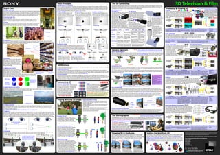
  • 1. 3D Television & Film For more information on Sony training courses, seminars and sessions, contact :- Sony Professional Education and Knowledge, Sony Europe, Jays Close, Basingstoke, Hampshire, RG22 4SB, United Kingdom. Tel: +44 (0) 1256 483224 Fax: +44 (0) 1256 328767 Every effort has been made to ensure that the information contained on this poster is useful, accurate and correct. However Sony Training Services cannot be held responsible for minor errors as a result of printing, advances in technology, changes in standards, and improvements in working practices. If you find any errors or anomalies in this poster please inform Sony Training Services at any of the contacts below. A complete list of changes from previous versions is available from Sony Training Services. Correct to March 2010. training.services@eu.sony.com www.pro.sony.eu/training R Professional Sony Education and Knowledge Version 3.0 Playing with the 3D image With the 2 cameras set up correctly, the 3D image can be modified to give the image more depth, or position it either nearer or further away. How to enhance a 3D shot With the image shown here, shot with two cameras there are two adjustments that can be made, the inter-axial distance, or toe-in angle. The cameras are placed a nominal 65mm apart, parallel to one another. This produces a reasonable 3D image, with a pleasing amount of perceived depth for this scene. The whole scene will be in front of the screen. Standard 3D shot When the distance between the two camera, commonly referred to as the inter-axial distance, is increased, the perceived depth increases and the distance between object in the scene appears to increase. However care should be taken not to increase the inter-axial distance too much. Close objects will appear closer, but will not grow any larger. The 3D illusion may break if the inter-axial distance is too large. (See .)Depth Cues Increased inter-axial distance When the angle between the two cameras is altered to point them slightly towards each other, commonly referred to as the toe-in angle, the perceived 3D image goes further into the distance, even though the various objects appear to be separated by the same distance. Care should be taken not to push the 3D scene back too far. Objects in the distance may force eyes to diverge which may cause eye strain. Excessive toe-in angles will also introduce keystone errors which will need to be corrected later. (See .)Camera Rig Errors Altered toe-in angle Note : Toe-in is performed on the camera rig and introduces keystone errors. Convergence is a planar move with no keystone errors. It cannot be performed in the camera rig and must be performed in post-production. Camera rig errors The most common errors when working with 3D are misalignment of the cameras in the camera rig. Both cameras must be set at the set at the appropriate inter-axial distance for the scene (See ). They must also be perfectly aligned with one another so that the two images can be mapped on top of one another on the display to provide a good 3D image. Inter-axial Distances Camera rig misalignment Another common error in 3D is lenses that are not properly matched or a lens pair that does not operate correctly as a pair. The same kind of lens should be used for both cameras in a 3D camera rig. For supreme quality the lenses should be selected and matched to have the same optical and mechanical characteristics. Lens pairing errors The lens may be misaligned to the sensor in the camera, or may suffer from misalignment within its own mechanics. Any misalignment between the lens and the camera sensor shows up as an optical axis error. This can be corrected by remounting the lens to the camera, or electronically in post-production. It is better to perform this adjustment in the camera and lens as this maintains the best image quality. However this may be impossible and may need to be performed electronically. (See )3D Tax Lens misalignments Height (Y) Tilt (Pitch) Toe-in (Yaw) Roll Any misalignment in the camera lens mechanics may show up as or . This is the small deviation in the optical axis as the lens is zoomed or focussed. This error is not normally a problem in single cameras, but may be significant in a 3D camera rig where the cameras need to be perfectly matched. Zoom and focus wander may be a straight line or simple curve, or may be a complex spiral if any rotating lens elements are slightly misaligned. zoom wander focus wander ZoomIris Focus Wide Angle Telephoto Centre of image True centre Actual centre Zoom wander True zoom centre line Sensor centre Lens centre Ideally both cameras in a 3D camera rig should be the same type, possibly selected and matched. If the two cameras are different, they may have different video formats or resolutions. Their video processing characteristics may differ. Cameras should also be colour matched, and white balanced so that their colour and brightness characteristics are the same. Camera characteristics mismatch Optical axis error Common lens related errors include badly coupled zoom, focus and iris controls. Both lenses should track each other exactly through these three parameters, either by electrically coupling the lenses together, or by providing accurate remote control to both lenses at the same time. Most small camera rig errors can be corrected in post-production. However cannot be corrected. Therefore it is vital that focus is matched as accurately as possible in the rig. focus The importance of focus The loss in quality due to the a mismatch between the left and right images. Only the straightened overlap region between the two images can be used. Stereographers try to keep 3D Tax below 5% 3D, and certainly below 10%. 3D Tax : Depth Cues Humans have eight depth cues that are used by the brain to estimate the relative distance of the objects in every scene we look at. These are listed below. The first five have been used by artists, illustrators and designers for hundreds of years to simulate a 3D scene on paintings and drawings. The sixth cue is used in film and video to portray depth in moving objects. However it is the last two cues that provide the most powerful depth cues our brains use to estimate depth. The eight depth cues 1. Focus When we look at a scene in front of us, we scan over the various objects in the scene and continually refocus on each object. Our brains remember how we focus and build up a memory of the relative distance of each object compared to all the others in the scene. 2. Perspective Our brains are constantly searching for the vanishing point in every scene we see. This is the point, often on the horizon, where objects become so small they disappear altogether. Straight lines and the relative size of objects help to build a map in our minds of the relative distance of the objects in the scene. 3. Occlusion Objects at the front of a scene hide objects further back. This is occlusion. We make assumptions about the shape of the objects we see. When the shape appears broken by another object we assume the broken object is further away and behind the object causing the breakage. 4. Lighting and shading Light changes the brightness of objects depending of their angle relative to the light source. Objects will appear brighter on the side facing the light source and darker on the side facing away from the light source. Objects also produce shadows which darken other objects. Our brains can build a map of the shape, and relative position of objects in a scene from the way light falls on them and the pattern of the shadows caused. 5. Colour intensity and contrast Even on the clearest day objects appear to lose their colour intensity the further away that they are in a scene. Contrast (the difference between light and dark) is also reduced in distant objects. We can build a map in our minds of the relative distance of objects from their colour intensity and the level of contrast. 6. Relative movement As we walk through a scene, c object compared to others provides a very powerful cue to their relative distance. Cartoonists have used this to give an impression of 3D space in animations. Film and television producers often use relative movement to enhance a sense of depth in movies and television programs. lose objects appear to be moving faster than distant objects. The relative movement of each 7. Vergence 8. Stereopsis Stereopsis results from binoccular vision. It is the small differences in everything we look at between the left and right eyes. Our brains calculate which objects are close and which objects are further away from these differences. Out of focus In focus In focus Out of focus Simple shapes with no shading. Same shapes with shading gives a powerful sense of depth. Teacup obscures the teapot Vergence is a general term for both divergence and convergence. If we look an objects in the far distant both our eyes are pointing forwards, parallel to each other. If we focus on an object close up, our eyes converge together. The closer the object, the more the convergence. Our brains can calculate how far away an object is from the amount of convergence our eyes need to apply to focus on the object. Film and video producers can use divergence as a trick to give the illusion that objects are further away, but this should be used sparingly because divergence is not a natural eye movement and may cause eye strain. Unsaturated colours Saturated colours The statue appears slightly to the right in the left eye image when compared to the buildings behind from the right eye image. The brain interprets this as the statue being nearer than the buildings. Vanishing point The light on the left and shadow on the right provides a very strong sense of 3D shape and form. The flower obscures the face, therefore the flower must be in front. Note : Unfortunately, it is impossible to show this depth cue on a static poster. Interoccular distance or inter-pupillary distance (about 65mm) If many of these depth cues combine they can offer a very strong sense of depth. In the picture to the right you will find perspective, lighting and shading, relative size, and occlusion which all combine to produce a very strong sense of depth in the picture. Combining depth cues Basic Principles In 3D two images are projected onto the display. By wearing a special pair of glasses the two images are split so that each eye only sees one of the two images. When comparing the left and right eye images, every object in the scene is horizontally displaced by a small amount. The brain assumes these two displaced objects are actually one object, and tries to fuse them together. The only way it can do this is to assume the object is either in front or behind the screen plane. The direction and amount of displacement defines where each object is in the 3D space. Placing objects in a 3D space Positive parallax The object is displaced slightly to the left for the left eye and slightly to the right for the right eye. The brain assumes this is only one object behind the screen. Zero parallax The object for the left eye and right eye are in the same position on the display. The brain sees this as one object on the screen plane with no 3D diplacement. Negative parallax The object is displaced slightly to the right for the left eye and slightly to the left for the right eye. The brain assumes this is one object in front of the screen. Projected image Projected image Projected image Pushing the limits Projected imageProjected image ? Excessive convergence on the display causes the eyes to converge beyond their normal limit, which either breaks the 3D illusion or causes eye strain. Film producers, programme makers and games designers will use these basic principles to provide a 3D rich experience to viewers. However it is the stereographers job to moderate the excesses of 3D so that everyone can enjoy 3D movies, games and programmes that both look good and do not push the limits of our ability to see 3D. (See .)The Stereographer Divergence, no matter how small the amount, is unnatural to humans. This will either break the 3D illusion or cause eye strain. Shuttered Wavelength Multiplex Visualisation Each image is filtered down to its primary colours, red, green and blue, with a narrow band filter. The exact primary colours are slightly different for each image. Thus the two images can be combined on the display, and still differentiate each one. The glasses contain a narrow band diachroic optical filter in each eye, exactly matched to the narrow band filters used in the display. Thus each eye only sees the part of the combined images intended for it. In circular polarisation one image is filtered with a clockwise polariser and the other with an anti-clockwise polariser before the images are combined. Left Right Right Right Right Left Left Left Left Left Right Right Advantages Disadvantages Usage Trademarks Quite inefficient. Requires a high speed display or projector. Prone to flickering if the frame rate is not high enough. Active and expensive glasses. Impractical for cinema use where the glasses need cleaning and charging between movies. (Home grade glasses have a battery life of about 80-100 hours. Cinema grade glasses have a battery life of about 250-350 hours.) Good for home use because the screen is just as bright for normal 2D video as it is for 3D video, and Cost of glasses not so much of a problem in where things are cared for much more. Manufacturers are working to standardise these glasses so that they can be used on any screen. Used in some cinemas where medical wipes are handed out rather than washing the glasses. Ticket price either includes a deposit or security is high due to cost of glasses. Good colour. Wide angle of view. Bright clear image for both 2D and 3D. Sony. XpanD. NVIDEA Panasonic. Samsung. Advantages Disadvantages Usage Trademarks Quite inefficient. Expensive glasses. ‘Thin’ colour. Prone to flickering if frame sequential displays are used. Good for cinemas that cannot install the silvered screens required by the circular polarising system. However high cost of glasses means either a deposit is paid on the glasses, or security is high. Good separation. Wide angle of view. Can be used in cinemas on a normal matt white screen. Dolby. Infitec. Each image is shown on the display separately, one after the other, left, right, left, right, at a fast enough rate to overcome flickering. The display also extracts an infra-red synchronisation signal which is sent to the glasses to tell them which image is being displayed. The glasses are active, and use an LCD shutter in each eye to sequentially shut each eye, while opening the other. The signal keeps the glasses synchronised with the display, and each eye only sees images intended for it. Advantages Disadvantages Usage Trademarks Requires special display technology with polarising filters. Darker image. Prone to flickering if frame sequential technology is used. Reduced angle of view and requires a silvered screen in cinemas. Popular in cinemas because the glasses are cheap and can easily be washed and reused. Good for professional monitors because the frame rate is not affected and these monitors are generally only used to view 3D material. Not so good for home use where the screen is darker even for normal 2D viewing. Better colour than anaglyph. Cheap glasses. Viewer’s head may be tilted. Easily adapted to existing display and screen technologies because high frame rates are not required (see system).Shuttered RealD. MasterImage. Zalman. Intel InTru3D Sync pulse PRO 200Hz Displaying & Viewing 3D Anaglyph Anaglyph is the oldest, and still the most common of the current methods of showing 3D. There are several different anaglyph standards all using two opposite colours. The most common has a red filter for the left eye and cyan for the right eye. The two images are filtered, cyan for left and red for right and combined into a single image. The glasses split the combined image into two images, one for each eye. or or The ratio of the amount of light each lens lets through for its own eye compared to the amount of light cut for the other eye. Extinction ratio : Is anaglyph the wrong way round? The diagrams shown here may seem the wrong way round. Why? The left image is cyan filtered, but the left eye is red filtered. Anything that is cyan in the picture appears black in the left eye and white in the right eye. Therefore the colours appear to be the wrong way round but are actually correct. Try the test below with a pair of red/cyan anaglyph glasses. LEFT BOTH RIGHT Circular polarisation Both images are circularly polarised on the display and shown together. The left eye clockwise and the right eye anti- clockwise. The glasses have a circular polarising filter for each eye, clockwise for the left eye and anti- clockwise for the right eye. Thus the glasses split the displayed image back into two images, one for the left and the other for the right eye. In linear polarisation one image is filtered with a vertical polariser and the other with a horizontal polariser before the images are combined. Sony 4K Cinema Projector The Sony 4K projector uses circular polarisation to show 3D movies. The 4K frame is divided into two 2K frames, one above the other. These are projected through a special lens with two lens turrets and two polarising filters onto the screen. 4K frame Left Right Left Right Combined image Linear polarisation Both images are linearly polarised on the display and shown together. One eye vertically and the other horizontally. The glasses have a linear polarising filter for each eye, one vertical, the other horizontal. Thus the glasses split the displayed image into two images, one for each eye. Note : Some glasses are set at +45 and -45 so that they can be used either way round. Advantages Disadvantages Usage Trademarks Inefficient. Poor colour reproduction. Requires exact match between display & glasses. Good for magazines, posters and other printed material. Older cinema and video system, but largely replaced by newer better systems. Established system. Cheap. Easily reproduced on screen or printed material. No special display needed. Advantages Disadvantages Usage Trademarks Requires special display technology with polarising filters. Darker image. Viewer’s head must be exactly vertical. Used in the early days of polarising screen. Largely replaced by circular polarisation due to the head tilt position problem (see ).Disadvantages Better colour than anaglyph. Cheap glasses. or TrioScopics. ColorCode. NVIDEA (3D Discover) For a diagram of linear polarisation see circular polarisation below. Original image 400 450 500 550 600 650 700 Wavelength (nm) Lightintensity Left filter Right filter Combined signal The Stereographer The stereographer is a new vocation in film, television and video games production. This person will monitor material from one or more 3D camera rigs and check that the 3D image is correctly aligned and positioned in the 3D space. The stereographer will also ensure that the 3D image is kept within the allocated depth budget throughout post-production. The MPE-200 is designed as the . Stereographers can use it to monitor the feeds from 3D camera rigs and finely tune the two camera outputs to obtain the best quality 3D image. The MPE-200 can also be used to modify the 3D image, to tune the 3D look, adapt the depth of the image, and maintain the 3D field with a given depth budget. stereographer’s dream The Sony MPE-200 3D Processor Box The amount of perceived depth in front and behind the screen plane, expressed as mm, pixels or percentage. For example stereographers work on a depth of about 2% depth budget for a 40" TV screen. Depth Budget : 3D Blindness It is estimated that about 5% of people cannot see 3D. There are many reason for this, some of them connected with the eyes, and others connected with the brain. Ophthalmic problems Problems with the eye include blindness, amblyopia (lazy eye), optic nerve hypoplasia (underdeveloped eye), strabismus (squint eye). Anyone with total blindness in one eye cannot see 3D. However such people are able to estimate depth by using any combination of the first six depth cues, which do not require two eyes. Those with lazy, underdeveloped or squint eye will subconsciously compensate by using these depth cues. (See .)Depth Cues Cerebral problems Tests have shown that our ability to calculate and distinguish 3D information in what we see around us is constructed in our brains in the first few months of our lives. Some people with ophthalmic problems in early infancy may never be able to see 3D, even if the ophthalmic problem itself is cured in later life. In some milder cases, careful practice will allow such people to see 3D movies and video. In severe cases those people may never be able to understand 3D moves and video. The 3D Camera Rig A few different ideas have been devised for shooting 3D material over the years, including some interesting cameras using arrangements of lenses and prisms to make a more portable, easy to use, single bodied camera. However, to date, the most effective way of shooting 3D material in a professional environment is the dual camera 3D camera rig. There are several configurations of 3D camera rig, each with advantages and disadvantages. Rig configurations The most compact dual camera 3D rig is the parallel rig. This places the two cameras next to each other. Parallel rigs generally work better with more compact cameras and lens designs. Otherwise it becomes difficult to achieve a good inter- axial distance between the cameras. It looks likely that this type of 3D rig will become the most popular because it is compact, and does not rely on mirrors which have an impact of image quality. New compact camera and lens designs will make this type of rig more appealing. The parallel rig The opposing rig places the cameras in a position where they are both pointing towards each other. A pair of mirrors placed between the camera reflects the images for left and right eye into the cameras. Both images are horizontally flipped. The opposing rig The mirror rig places one of the cameras vertically. A semi-transparent mirror reflects the scene into the vertical camera while also allowing the horizontal camera to see through the mirror. The mirror rig There are two basic forms of mirror rig. One with the vertical camera on top, and the other underneath, which has the advantage of a better centre of gravity, less spurious mirror reflection. A good quality mirror is vital in this type of rig. This type of rig is bulky and is not generally used in modern rigs but may return with new compact cameras. However it was popular with film cameras because it allows accurate camera line-up by removing the film plates and mirrors. Rig type Parallel Opposing Mirror Mirror Top mount Bottom mount Features Style Image flip Advantages Disadvantages Usage Compact & light design. No mirrors. 100% light in both cameras. Difficult to achieve small IAD with large cameras or lenses Easy lineup with film cameras. IAD set by mirror spacing. 100% light in both cameras. Bulky design with modern video and film cameras. Can achieve zero IAD even with large cameras. Requires very high quality mirror. Heavy design. Only 50% light in each camera. Similar to top mount rigs, but less prone to dirt, rain & light interference on the mirror. May have a problem pointing down. None. Both, horizontal. One, vertical. One, horizontal. Side by side cameras. Opposing cameras with two 45 mirrors. One horizontal, one vertical camera set above. Semi-trans. mirror. One horizontal, one vertical camera set below. Semi-trans. mirror. Compact and hand- held rigs. Good for boom or crane rigs. Used in the past with film cameras. Not in general modern use. Top mount Note : IAD = Inter-axial distance Bottom mount Popular in film and drama sets using large cameras, especially with bulky digital cinematography cameras. Prone to dust, rain & light interference on the mirror. Connecting 3D Dual Link HDSDI & 3G-SDI Dual Link is a popular method of connecting 3D signals in professional equipment. It consists of two cables and connectors at 1.485Gbps each, one for left and the other for right. However it takes up two inputs or outputs, effectively halving equipment capacity.3G-SDI is the new “stereo” connection for video, achieved by multiplexing together the two links of Dual Link into a single cable and connector at 2.97Gbps. HDMI Dual Link A Dual Link B YY YYPB1 PB0 P B2B3 PR0 PR1 P3G-SDI 2301 PB1 PR1 PB3 Y Y Y Y3 P P PB0 R0 B22 1 0 HIGH-DEFINITION MULTIMEDIA INTERFACE Introduced in May 2009, v1.4 adds 3D display methods, including line, field and frame sequences, Side-by-side and 2D+depth. Any 3D video equipment with HDMI should be v1.4. HDMI version 1.4 HDMI was originally developed for home use as a simple way of connecting high definition video equipment. Derived from DVI, it uses a 19 pin connector, with digital surround sound audio, a command protocol and HDCP (High-bandwidth Digital Content Protection) copy protection scheme. “3G makes 3D easier” Showing 3D in the home Good for normal broadcast transmission. Bandwidth & frame rate same as normal, but half horizontal resolution. Good for normal broadcast transmission. Bandwidth & frame rate same as normal, but half vertical HD resolution. Good for local transmission i.e. from a Playstation to TV. Resolution is full HD but the bandwidth & frame rate must be doubled to reduce flickering. Side-by-side There are several methods of delivering 3D into the home. These are digital off-air, satellite and cable transmission, internet and Blu-ray. At the moment, there are no special compression standards designed for 3D, therefore existing standards must be adapted. The left and right signals need to be combined into one HD frame sequence and sent over a normal transmission system. Top-over-bottom Frame sequencial Left Right Left Right Left Right Left Right Left Left Right Left Left Left Left Right Left Right Left Right Left Right Left Left Right Standard 1920x1080 HD frame Getting the best from 3D In real life we can tilt our heads and we see world at an angle. We still see depth, but the depth cues are at an angle. However 3D movies an illusion. They are carefully recorded with both cameras exactly horizontal to one another. Therefore just like the cameras were when the move was recorded. Tilt your head and the illusion becomes strained and eventually snaps. The picture on the left only works if you hold your head upright like a normal 3D movie. The picture on the right only works if you tilt your head to the left. 3D movies must be viewed with your head exactly upright Try the test below.