The document discusses several topics related to solar energy and photovoltaic systems:
1. It defines the solar constant as the solar energy received per unit time and area outside Earth's atmosphere, which is approximately 1367 W/m2.
2. It explains that solar insolation is the solar radiation received on a horizontal surface on Earth, which varies with atmospheric conditions and time of day, unlike the solar constant.
3. It introduces the clarity index as a ratio of solar insolation to the solar constant, ranging from 0.1 on cloudy days to 0.7 on clear days at noon.
4. It provides a brief overview of how a solar photovoltaic system works

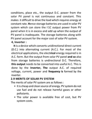
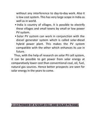
![𝑅𝑙 =
𝑑𝑣𝑐
𝑑𝐼𝑐
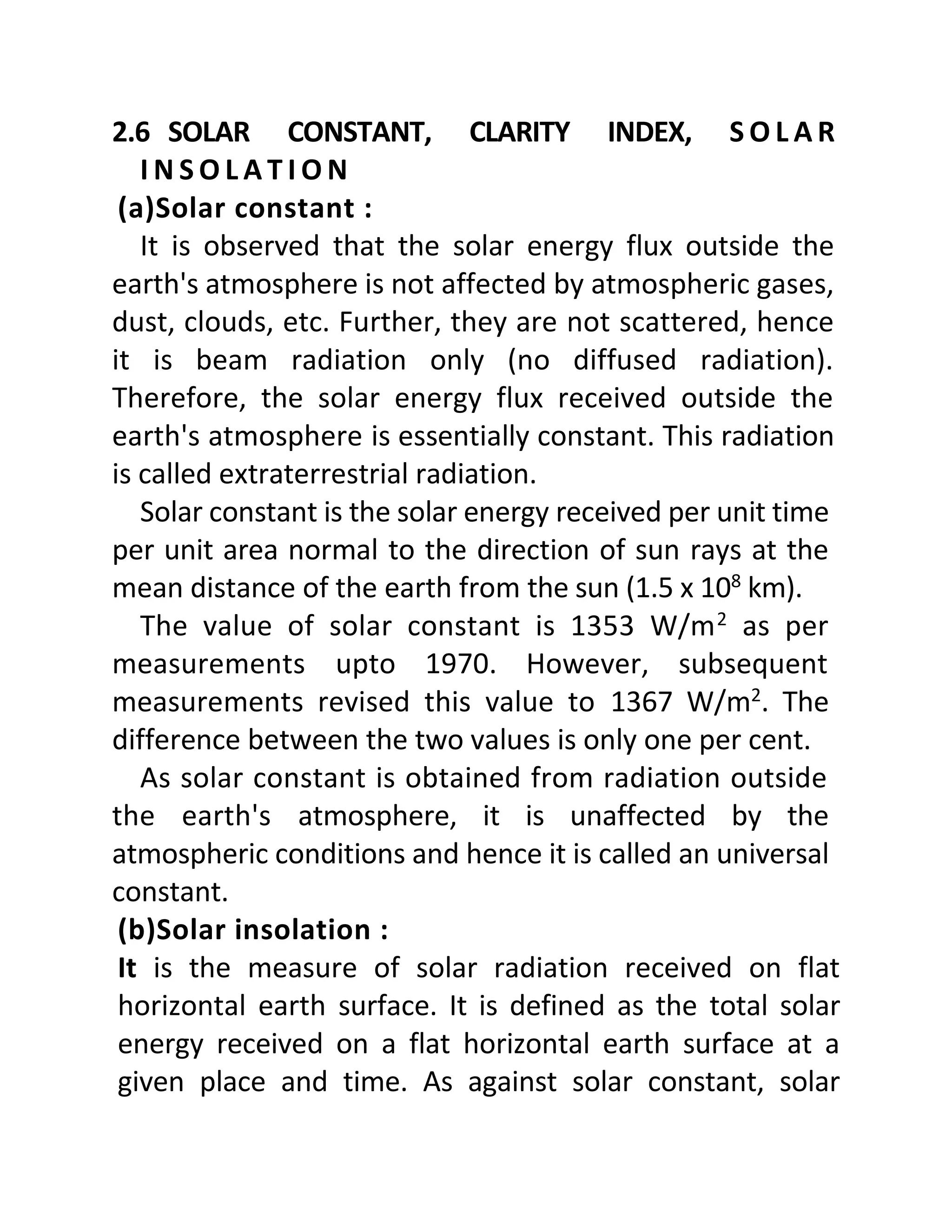
• When RL = 0, then current I = Isc. This is short circuit
current (Isc) which is maximum current delivered by
the solar cell. It is shown on Y-axis in Fig. 2.12. Here
voltage across load V = 0. Hence power delivered by
solar cell P = V x I.
P = 0xI= 0
• Multiply by 0.707 to the value of short circuit current
so that we get current Im, = 0.707 x Isc. From this value
of Im, draw a horizontal line parallel to X-axis. It
intersects the I-V characteristics [curve-I] at point A.
From this point, draw perpendicular on X-axis to get
corresponding value of voltage Vm. Then product of Im
andVm, gives maximum power point. Power Pmpp = Im
X Vm. At this value of load i.e. for these values of Im,
and Vm, the solar cell delivers maximum power to the
load. This maximum power is also shown by curve-H.
Thus adjust the load to get value of current Im, and
voltage Vm, so that one can have maximum power. This
point A is also called as knee point.
• When load RL = ∞ then I = 0 and V = Voc. This is the
maximum voltage across the load shown on X-axis
called open circuit voltage (Voc). At this value of load,
though voltage is maximum (Voc), the current
becomes zero. Hence power P = I x V = 0.](https://image.slidesharecdn.com/solar-energy-3-230221074218-bcec190b/85/Solar-Energy-3-docx-16-320.jpg)
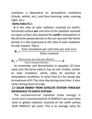
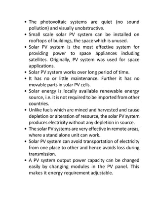
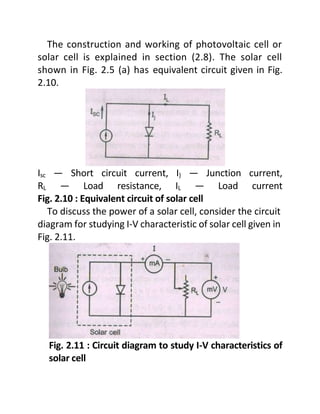
![• The variation of power delivered by solar cell from
zero at Isc, then maximum at Im, and Vm and again zero
at Voc is shown by curve-II in Fig. 2.12.
• The fill factor is a measure of photo junction inside the
solar cell which is effectively contributing to the photo
current. Not all junctions participate in giving
photocurrent because some are inactive or
defective. The fill factor is also a measure of
perfectness of I-V characteristics. If it is perfect
square (I-V characteristic), then FF = 1. In practice, fill
factor (FF) is less than 1. It is given as
Fill Factor =
Pmpp
Voc x Isc
Power of a solar PV panel:
If there are n solar cells in a module and there are m
modules in a panel, then power of a solar panel
(or array) Pp is written as
Pp = n x m x P
where P = V x I is power of single solar cell.
If RL is external load connected, Vp is D.C. output voltage of
the panel and Ip is D.C. output current of the panel, then Pp
becomes
Pp = Vp .Ip
𝑃𝑝 =
𝑉𝑃
2
𝑅𝐿
[sinceV=IR]](https://image.slidesharecdn.com/solar-energy-3-230221074218-bcec190b/85/Solar-Energy-3-docx-17-320.jpg)


![Polymer [ बहुलक ] Chemistry Notes PDF - Irfanullah Mehar - JJ Sir Chemistry.pdf](https://cdn.slidesharecdn.com/ss_thumbnails/polymerchemistrynotespdf-irfanullahmehar-jjsirchemistry-260210172118-3f9b37f7-thumbnail.jpg?width=640&height=640&fit=bounds)


